Page is loading ...

Before attempting to connect or operate this product,
please read these instructions carefully and save this manual for future use.
The model number is abbreviated in some descriptions in this manual.
Network Disk Recorder
Setup Instructions
Model No. WJ-ND300A
WJ-ND300A/G
A
LA
R
M
A
LA
R
M
S
U
S
PE
N
D
E
D
E
R
R
OR
TI
M
E
R
R
E
C
O
PE
RA
TE
1
-
L
IN
K
/
A
C
T-2
H
D
D
1
H
D
D
2
H
D
D 3
E
S
C
P
U
L
L
N
e
tw
o
r
k
Dis
c
Re
c
o
r
d
e
r
WJ
-
ND
300
300
A
S
E
T
H
D
D
4

2
CONTENTS
Preface ............................................................................................................................ 3
Features ...................................................................................................................... 3
About these Operating Instructions ............................................................................. 4
System Requirements for a PC ................................................................................... 4
Trademarks and Registered Trademarks ................................................................... 4
Abbreviations .............................................................................................................. 5
Terms Used in these Operating Instructions ............................................................... 5
Operations Flow .............................................................................................................. 7
Performing the Network Settings ..................................................................................... 8
Performing the Network Settings of this Unit .............................................................. 8
Performing the Network Settings of a PC ................................................................... 10
About the Network Security of this Unit ........................................................................... 13
Equipped Security Functions ...................................................................................... 13
For Enhanced Security ................................................................................................ 13
Display the Operation Window ........................................................................................ 14
About the Operation Window .......................................................................................... 16
Top Page ..................................................................................................................... 16
[Control] Tab ............................................................................................................... 17
[Cam Select] Tab ........................................................................................................ 18
[Setup] Tab (Quick) ..................................................................................................... 19
[Setup] Tab (Advanced) .............................................................................................. 20
Status Display Area ..................................................................................................... 21
Playback Point Operation Area ................................................................................... 23
[HDD] Tab ................................................................................................................... 23
[CAM] Tab ................................................................................................................... 25
Setup Menu (Quick) ........................................................................................................ 26
Setup Menu (Quick) Chart .......................................................................................... 26
Basic Operation with the Setup Menu (Quick) ............................................................ 26
Display/System Settings [Display Setup] .................................................................... 28
Camera Network Settings and Group Settings [Camera Setup] ................................. 30
[Rec & Event Setup] .................................................................................................... 31
Perform the Settings for Network [Network Setup] ..................................................... 35
Setup Menu (Advanced) Chart ........................................................................................ 37
Setup Menu (Advanced) Item List ............................................................................... 37
Basic Operation with the Setup Menu (Advanced) ..................................................... 40
Perform the Settings for the System [System] ............................................................ 42
Functions for Recording [Recording] ........................................................................... 46
Functions for Events [Event] ....................................................................................... 49
Settings for the Recording/Event Schedule [Schedule] .............................................. 53
Settings Relating to Cameras [Camera] ...................................................................... 60
Settings for Communication with other Devices [Comm] ............................................ 64
Settings Relating to the User Authentication [User Mng.] ........................................... 75
Settings for Maintenance [Maintenance] ..................................................................... 82
About the Hard Disk Drives ............................................................................................. 89
Summary of the RAID 5 function (Redundant Arrays for Independent Disks,
independent data disks with distributed parity blocks) ................................................ 89
Display the HDD DISK MENU ..................................................................................... 90
Initialize the Hard Disk Drive [Format] ......................................................................... 92
Remove the Hard Disk Drive from the System Logically [Remove] ............................ 96
Troubleshooting ............................................................................................................... 97

3
Preface
Features
The Network Disk Recorders WJ-ND300A series are designed for use within a surveillance system, and perform
recordings and playbacks pictures from network cameras in the system.
The network disk recorder is a recording device using a hard disk drive to record camera pictures instead of using
video tapes so that pictures recorded by repeated overwriting will not experience deterioration of the recorded pic-
ture quality.
Up to 32 cameras can be connected via a network and it is possible to record their camera pictures. It is possible to
perform the settings or operate the WJ-ND300A (this unit) using a web browser installed on a PC connected to a
network. Up to 8 PCs (web browsers) can access this unit concurrently and it is possible to perform the settings and
operate this unit.
"WJ-ND300A" is the generic name of the network disk recorders WJ-ND300A series.
Various Recording Functions
• Multi-recording
It is possible to perform multiple recordings using a single network disk recorder even if the operating environ-
ments are different, for example, recording pictures of cameras in different places at different times.
• Schedule recording
It is possible to perform recording automatically at a scheduled time on a designated day of a week. It is also
possible to perform recording at a different recording rate according to time range.
• Emergency recording
In the case of an emergency, emergency recordings will be given a higher priority than other recording modes by
operating an external switch.
• External timer recording
It is possible to perform recording automatically using an external timer.
• Event recording
At an event occurrence, such as an alarm signal is supplied, the recording mode (quality and recording rate) can
be changed to high quality to record pictures.
Downloading/Transmitting Images
It is possible to download (save) the currently displayed image in the web browser window onto the hard disk of a
PC. By establishing an FTP server, it is possible to transmit images to the designated FTP server periodically. When
an event occurs, it is possible to transmit images from the camera installed in the place where the alarm occurred.
Event Notification Function
When an event occurs, it is possible to send e-mails to designated addresses to notify of the event occurrence.
It is also possible to send an e-mail with an image recorded when the event occurred.
Security Function and Reliability
• User authentication function (registration of ID and password) allows users access to predetermined selection of
the available functions. Up to 32 users can be registered.
• Host authentication function restricts devices from operating this unit if their IP addresses are not registered.
• If a hard disk crashes, the RAID 5 function prevents any recorded pictures loss.
About these Operating Instructions
There are 3 sets of operating instructions for the WJ-ND300A as follows.
• Installation Guide (book)
• Operating Instructions (PDF)
• Setup Instructions (PDF, these operating instructions)

4
These "Setup Instructions" contain descriptions of how to perform the required settings to operate this unit using a
PC via a network and descriptions for installations such as how to connect the unit to other devices.
The network settings of the unit will be different depending on the settings of the LAN or the Internet service provider
to which the unit is to be connected.
Refer to an administrator of each network for further information about the respective network.
Refer to the "Installation Guide" for descriptions about available functions by operating this unit using the buttons on
the front panel. Refer to the "Operating Instructions" on the provided CD-ROM for descriptions of how to operate this
unit from a PC.
Adobe
®
Reader is required to read these operating instructions (PDF) on the provided CD-ROM. When the Adobe
®
Reader is not installed on the PC, download the latest Adobe
®
Reader from the Adobe web site and install it.
"WJ-ND300A" or "ND300A" shown in the illustrations used in these operating instructions indicate this unit or the
WJ-ND300A series.
Refer to "readme.txt" on the provided CD-ROM for further information including the dedicated software, its version,
and compatible cameras.
System Requirements for a PC
It is recommended to operate this unit using a PC that meets the following system requirements. If using a PC that
does not meet the following system requirements, it may cause problems such as slow imaging or the browser
becomes inoperable.
OS: Microsoft
®
Windows Vista
®
32-bit
Microsoft
®
Windows
®
XP Home Edition SP2*
Microsoft
®
Windows
®
XP Professional SP2*
OS Language: English, French, Spanish, German, Italian, Russian, Chinese
CPU: Pentium
®
4 3.0 GHz or faster
Memory: 512 MB or more (A minimum of 1 GB memory is required when using Microsoft
®
Windows
Vista
®
.)
Monitor: Resolution: 1 024 x 768 pixels or more
Color: 24-bit True color or better
Network interface: 10/100 Mbps Ethernet port x1
Web browser: Microsoft
®
Internet Explorer
®
6.0 SP2
* Windows
®
Internet Explorer
®
7.0 is required when using Microsoft
®
Windows Vista
®
(32-bit).
Other: CD-ROM drive: It is necessary to read the operating instructions and use the software on the
provided CD-ROM.
DirectX
®
9.0c or later
Adobe
®
Reader
®
: It is necessary to read the operating instructions on the provided CD-ROM.
Notes:
• When using a PC that does not meet the above requirements, displaying of images may become slow or the web
browser may become inoperable.
• Audio may not be heard if a sound card is not installed on a PC. Audio may be interrupted depending on the net-
work environment.
• Refer to "Notes on Vista
®
" (PDF) for further information about system requirements for a PC and precautions
when using Microsoft
®
Windows Vista
®
.
Trademarks and Registered Trademarks
• Microsoft, Windows, Windows Vista, Internet Explorer, ActiveX and DirectX are either registered trademarks or
trademarks of Microsoft Corporation in the United States and other countries.
• Intel and Pentium are trademarks or registered trademarks of Intel Corporation or its subsidiaries in the United
States and other countries.
• Adobe and Reader are either registered trademarks or trademarks of Adobe Systems Incorporated in the United
States and/or other countries.

5
• Other names of companies and products contained in these operating instructions may be trademarks or regis-
tered trademarks of their respective owners.
Abbreviations
The following abbreviations are used in these operating instructions.
Microsoft
®
Windows Vista
®
is described as Windows Vista.
Microsoft
®
Windows
®
XP Professional SP2 and Microsoft
®
Windows® XP Home Edition SP2 are described as
Windows XP.
Terms Used in these Operating Instructions
HDD
Refers to a hard disk drive (mass storage medium). The unit records camera pictures on a hard disk rather than on
video tape.
Recording rate (ips, I-Frame)
Refers to the unit that determines the smootheness with which the recorded images are played back. "ips" is used to
express the number of frames recorded per second. The higher the number, the smoother the movement, but the
available recording time becomes shorter. "I-Frame" is used to express the refresh interval set on the camera.
Resolution
Resolution refers to the degree of fineness and quality of the camera pictures recorded by this unit. This unit dis-
plays the resolution in number of dots. For example, if the number of horizontal dots is 720 and the number of verti-
cal dots is 480, the display reads 720 x 480.
M-JPEG
A video codec that compresses video fields from the camera into independent JPEG images sequentially by query
from the unit.
Network load will be reduced comparing with the method that obtains JPEG images independently from the camera.
However, the transmission rate will fluctuate depending on the state of the camera.
Some cameras phrase this video codec as just "JPEG".
Manual recording
Function for starting and stopping recording manually by clicking the recording button or recording stop button.
Schedule recording
Function for starting and stopping recording automatically at a preset time.
Event recording
Function for starting recording automatically when an event occurs.
Event recordings are divided into pre recordings (pictures before the event occurs) and post recordings (pictures
after the event occurs).
Emergency recording
Function for performing priority recording in emergency situations, etc. through an external switch connected to the
unit.
SD memory recording/SD memory data
Function featured in some Panasonic’s cameras that saves images on the SD memory card on the camera when
communication with the camera failed in the period set for the schedule recording of this unit. Images saved by the
SD memory recording are described as "SD memory data" on these operating instructions. The recording time of SD
memory data will be displayed based on the clock of the camera.

6
External recording mode
Function for changing the time schedule through an external switch connected to this unit. While the switch is turned
on, recording is performed according to the time schedule specified for external recording.
Event
An event is a phenomenon which triggers a specific operation (event operation) in the unit. Events are divided into
terminal alarm, command alarm, and site alarm.
Event Action
Event action refers to a specific operation performed when an event occurs. Event operations are divided into ALM
(Alarm Mode), ADM (Activity Detection Mode), and are selectable. In ALM, the occurrence of an event is announced
by screen display, LED, or buzzer (Alarm Operation). In ADM, the occurrence of an event is not announced, but the
unit starts event recording, performs the preset operations, and enters the event into the event log. In OFF mode,
the unit only enters the event into the event log.
Sequence
Sequence refers to automatically changing the displayed camera picture in a preset sequence. Sequence display is
possible while the unit displays live pictures.
Electronic zoom
Function for enlarging live and playback pictures. While the camera uses the camera zoom function to enlarge pic-
tures, the electronic zoom function enlarges the picture electronically in the unit and displays it.
Camera control
Camera control refers to controlling the functions of the combination cameras connected to the unit. These functions
include Pan/Tilt, Zoom, Focus, Brightness, Preset Operations (moving the camera to a preset horizontal/vertical
position), and Auto (for example, automatic panning).
A-B repeat playback
Function for playing back repeatedly between a set start point (A) and an end point (B) in playback mode.
HDD safety mode
Function for turning off the power supply to the HDD to prevent damage of the HDD due to vibration and shock if the
unit is mounted in or dismounted from the rack with the power turned on.
Disk config
When an HDD is replaced, removed, or added, the HDDs need to be newly configured. Disk config refers to the
menu for performing these HDD settings.
RAID (RAID5)
This stands for Redundant Arrays of Inexpensive Disks. It refers to a technology to implement a high-speed large-
capacity and high-reliability disk unit by distributing access to multiple HDDs. If trouble occurs in one of the HDDs,
the data on the faulty HDD can be recovered based on the error correction data recorded on the other HDDs.
(RAID5 is used when 3 or more HDDs are connected. If trouble occurs simultaneously in 2 or more HDDs, the data
of the faulty HDD cannot be recovered.)
System Administrator
This refers to a person who has the responsibility and authority to operate the unit and perform settings.

7
Operations Flow
The operation flow of this unit is as follows.
Rack Mounting
Install the unit in the rack.
Refer to the Installation Guide for further information
about rack mounting.
➜
z
Connections
Refer to the provided Installation Guide for further infor-
mation about connections.
➜
x
Startup
Turn on the power of the unit.
For further information, refer to the Installation Guide.
➜
c
Network settings of this unit
(page 8)
Operate the buttons on the front panel of the unit to per-
form the network settings of the unit.
➜
v
Network settings of the PC
(page 10)
Change the TCP/IP setting of the PC to conform to the
settings of this unit.
➜
b
Format (initialize) hard disk drives
(page 92)
Display the disk configuration menu and format the
hard disk drives.
➜
n
Display the camera setup menu and
perform the network settings of
cameras. (page 30)
Refer to the Setup Instructions (PDF) for descriptions of
how to display the camera setup menu.
➜
m
Setup (pages 26 - 88)
Start operation
Perform the required settings on the setup menu to
start operation.
➜
,

8
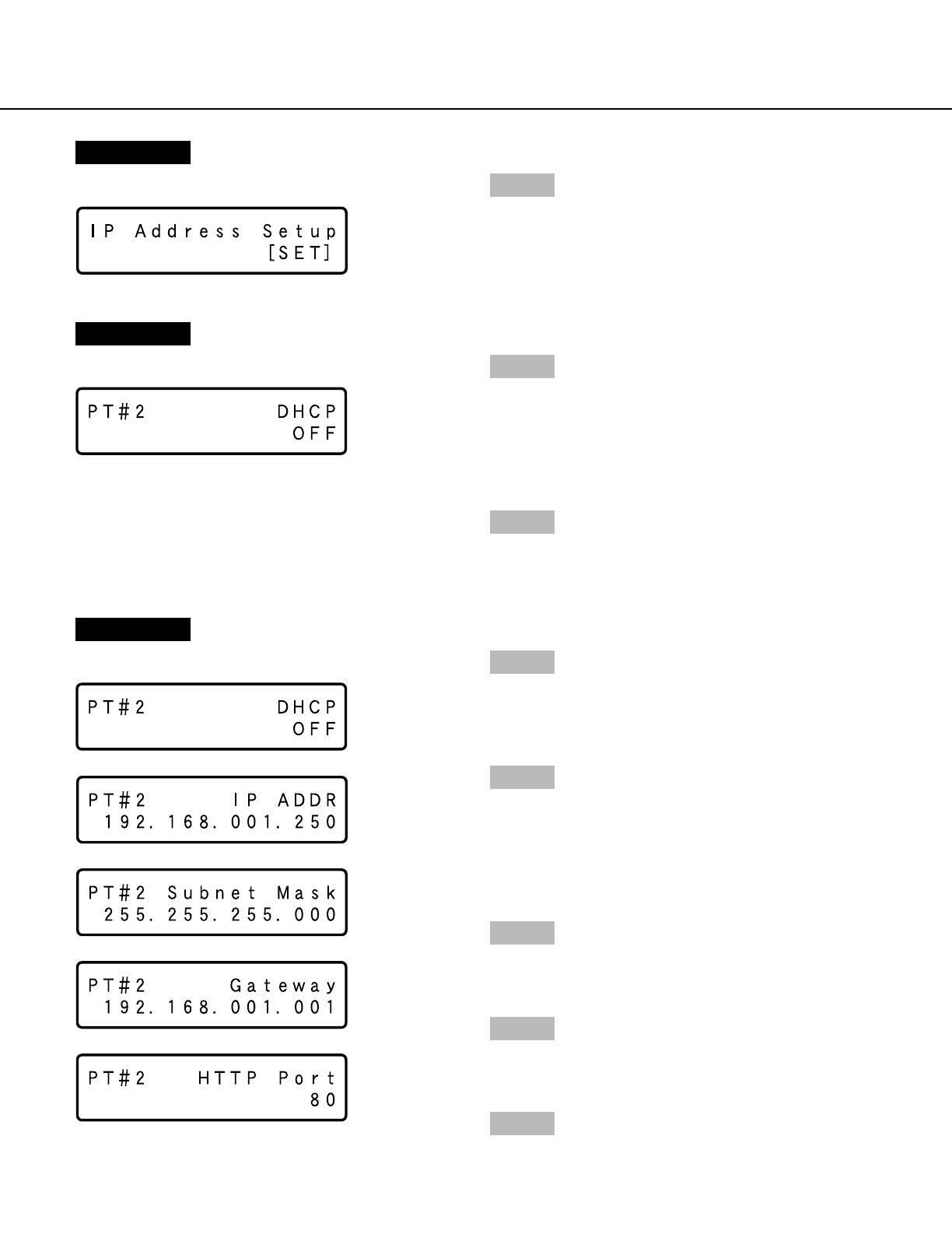
Performing the Network Settings
Screenshot 1
Start operation when the standby display is displayed
on the LCD.
Step 1
Display the IP address setup display by pressing the
arrows button (C or D).
With the following network environment, it is not necessary to perform the network settings. It is possible to perform
the settings or operate this unit using a web browser after completing the connection.
IP Address: 192.168.1.2 - 192.168.1.249, 192.168.1.251 - 192.168.1.254
Subnet mask: 255.255.255.0
Gateway Address: 192.168.1.1
When the network settings are different from the settings above, perform the network settings of this unit and the
PC.
It is necessary to display the camera setup menu to perform the network settings of cameras. It is possible to display
the camera setup menu on the "NW Camera Setup" menu of the setup menu ("Camera" – "NW Camera Setup").
Performing the Network Settings of this Unit
Perform the following settings relating to network.
Operate the buttons on the front panel of the unit to perform the network settings of the unit. The settings items will
be displayed on the LCD.
• DHCP
• IP Address
• Subnet mask
• Gateway
• HTTP port
The default network settings of each port are as follows.
DHCP
IP address
Subnet mask
Gateway
HTTP port
OFF
192.168.0.250
255.255.255.0
192.168.1.1
–
OFF
192.168.1.250
255.255.255.0
80
–
192.168.2.250
255.255.255.0
–
–
Camera port Client PC port Maintenance port
Important:
Network settings for each port (IP address, etc.) should be on a different subnet. Otherwise, network communica-
tion may be failed.
9
Screenshot 3
The DHCP Setup window will be displayed.
Screenshot 4
The setup item display for each item will be displayed.
Step 5
After confirming that the cursor is positioned on "l",
press the [SET] button, and move the cursor to the
number area.
Step 6
Set the value as follows. The cursor appears as a "_"
(underscore).
To move the cursor: Press the arrows button (A) or
(B).
To input values: Press the arrows button (C) or (D).
Step 7
After setting the value, press the [ESC] button to move
the cursor on "l" and finalize the setting.
Step 8
To set the next item, press the arrows button (C) or (D)
to change the menu screen.
Step 9
Repeat steps 5 – 7 to set other items.
Step 3
Select the desired network port by pressing the arrows
button (A or B).
PT#1: Camera port
PT#2: Client PC port
PT#3: Maintenance port
Step 4
Display the desired settings item by pressing the arrows
button (C or D).
>
–
>
–
>
–
>
–
>
–
>
–
Screenshot 2
The IP address setup display will be displayed.
Step 2
Press the [SET] button.
10
Performing the Network Settings of a PC
Change the TCP/IP setting of the PC to conform to the settings of this unit.
It is required to set the IP address of the PC to "192.168.1.XX (a number from 2 to 254 except 250)" to access this
unit.
In these operating instructions, the settings are performed on Windows XP as examples. Refer to the operating
instructions of the respective OS for further information.
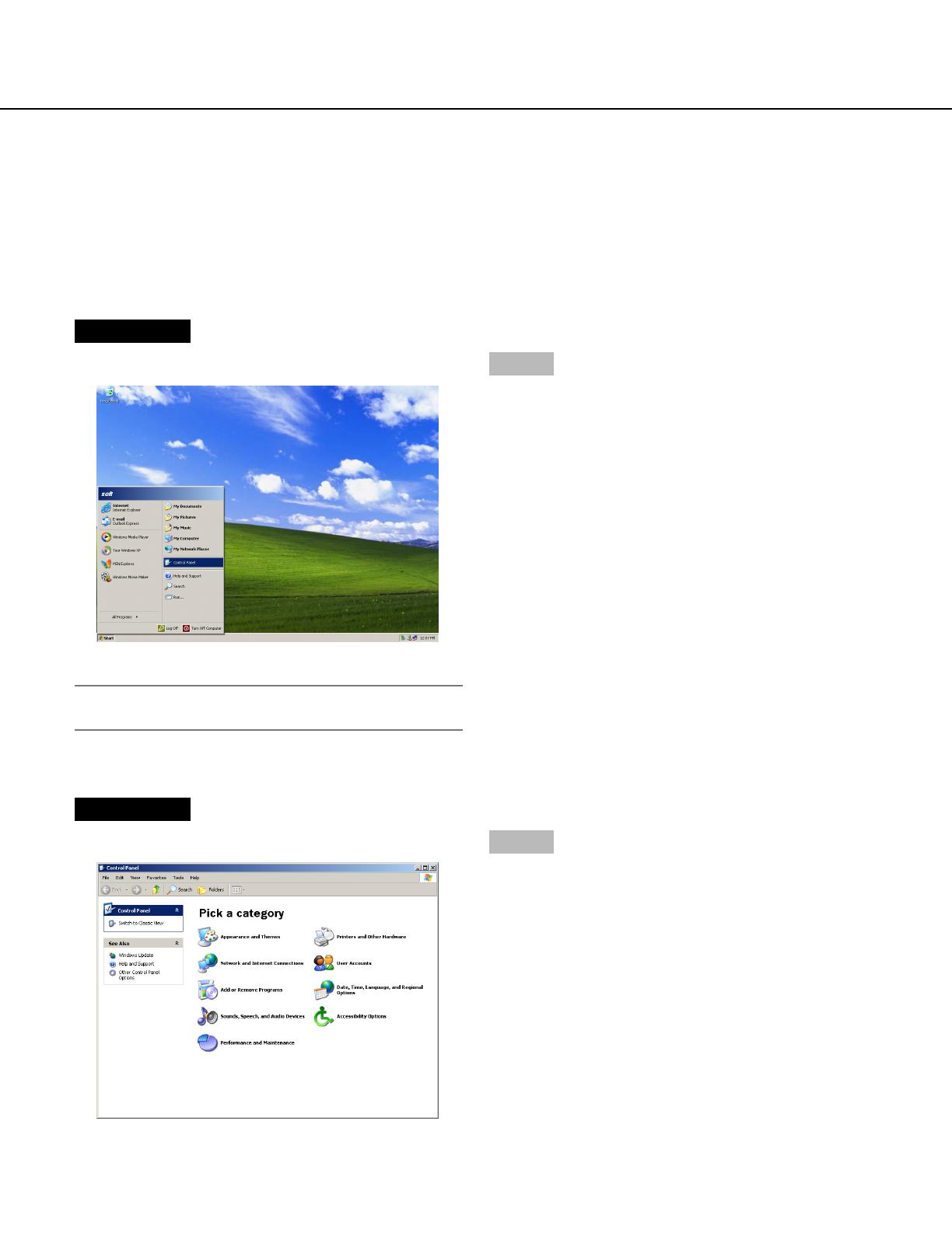
Screenshot 1
Start just after the PC is started up.
Important:
Log in to the PC as an administrator.
Step 1
On the taskbar, click "Start", and then click the "Control
Panel".
Screenshot 2
The control panel will be displayed.
Step 2
Click the "Network and Internet Connections" icon.
11
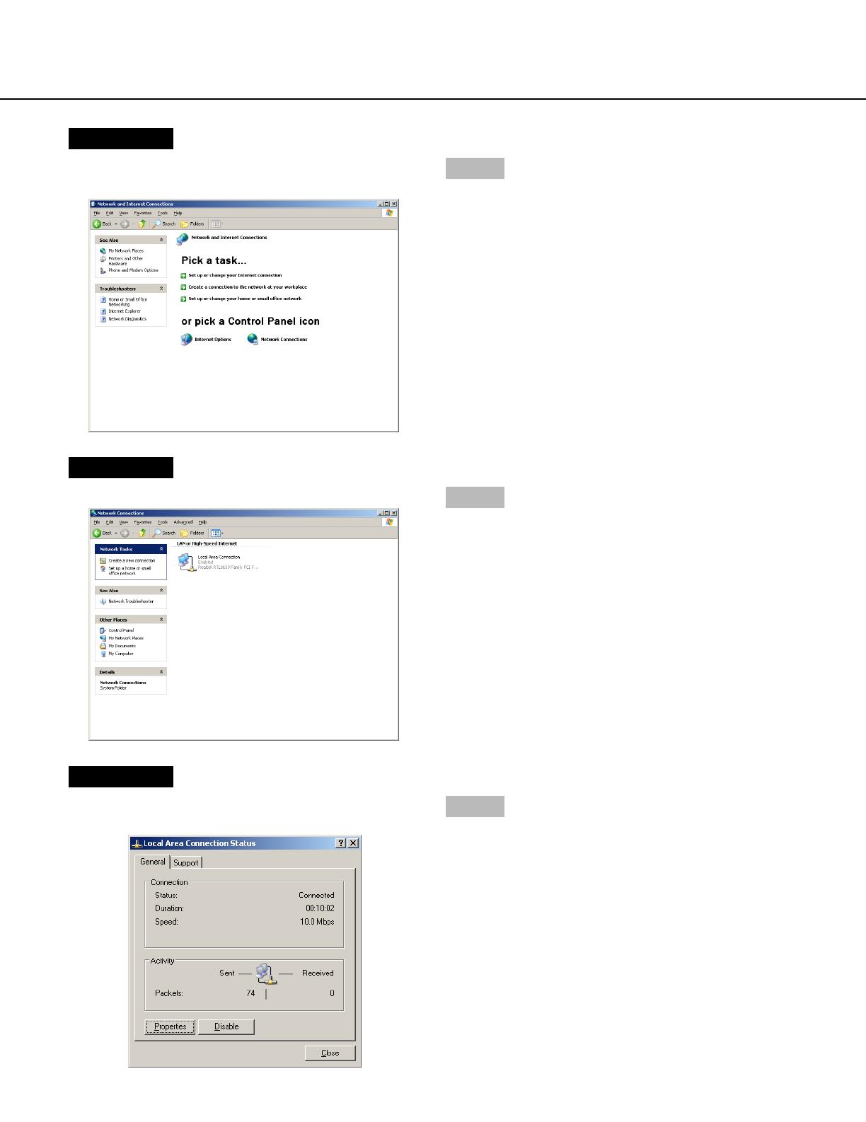
Screenshot 3
The "Network and Internet Connections" window will be
displayed.
Step 3
Click "Network Connections".
Screenshot 4
The "Network Connections" window will be displayed.
Step 4
Double click "Local Area Connection".
Screenshot 5
The "Local Area Connection Status" window will be dis-
played.
Step 5
Click "Properties".
12
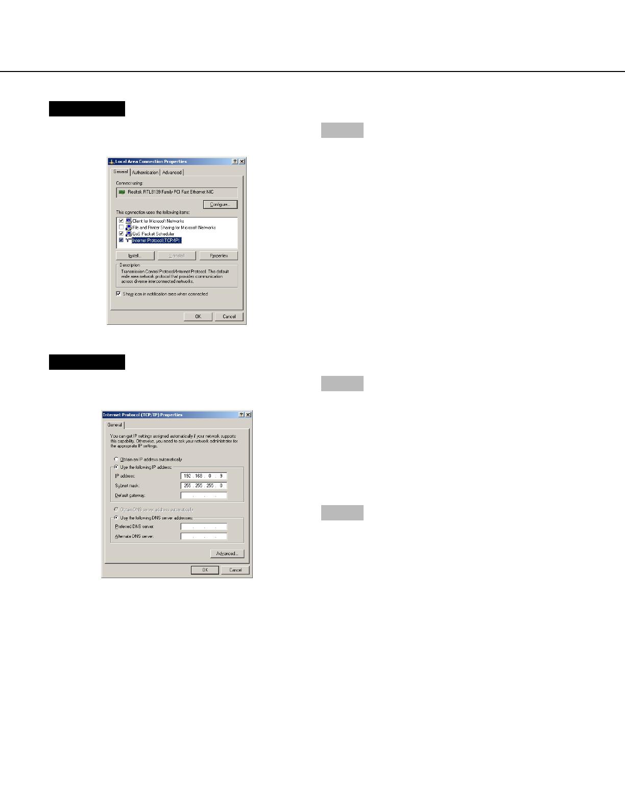
Screenshot 6
The "Local Area Connection Properties" window will be
displayed.
Step 6
Click "Internet Protocol (TCP/IP)", and then click
"Properties".
Screenshot 7
The "Properties" window of "Internet Protocol (TCP/IP)"
will be displayed.
Step 7
Click "Use the following IP address" and enter the IP
address and the subnet mask as follows;
• IP address: 192.168.1.100
• Subnet mask: 255.255.255.0
Depending on the network configuration, it may be nec-
essary to set the "Default gateway". Refer to a system
administrator for further information.
Step 8
Click the "OK" button and close the window.
13
Equipped Security Functions
q Access restrictions by the host authentication and the user authentication
It is possible to restrict users from accessing this unit by setting the host authentication and/or the user authenti-
cation to on. (page 75)
w Access restrictions by changing the HTTP port
It is possible to prevent illegal access such as port scanning, etc. by changing the HTTP port number. (page 65)
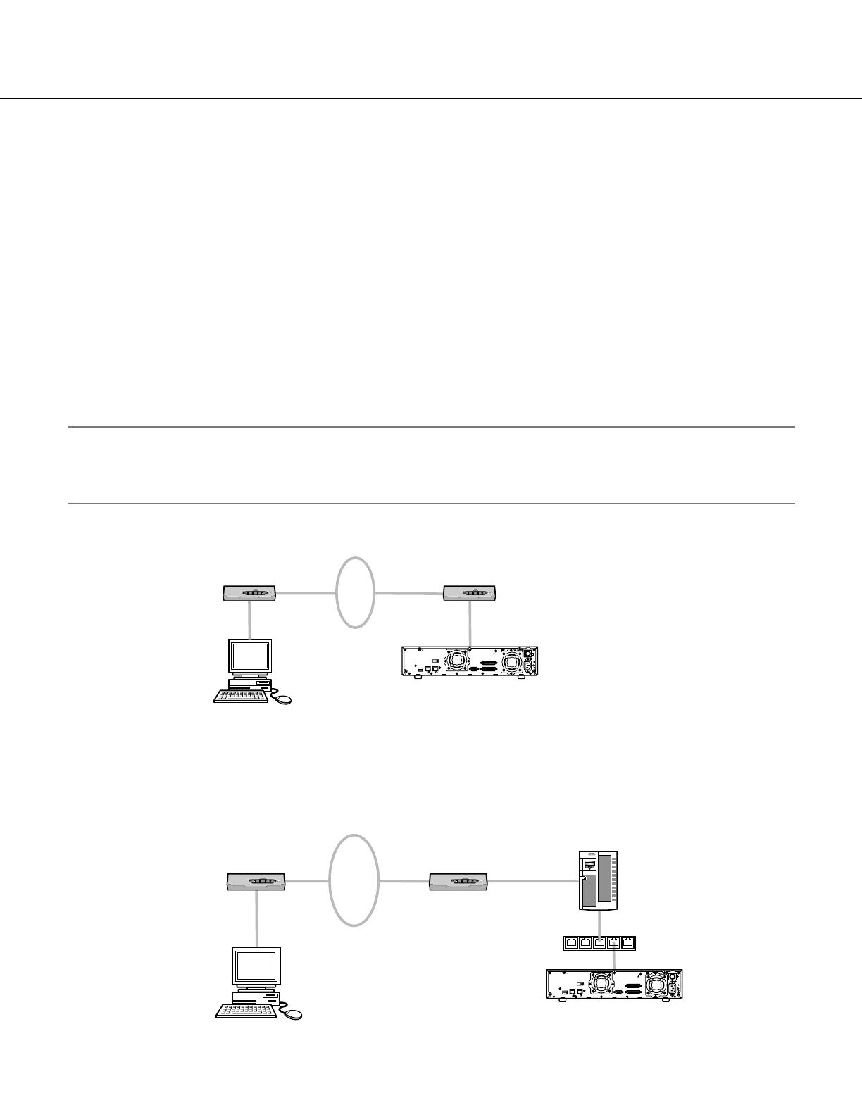
For Enhanced Security
Divide the subnet using a router to enhance the network security by double authentications of IP addresses using
this unit and a router. When required to connect this unit with a network without enhanced security, connect the unit
after the network security is enhanced, such as by installing a VPN (Virtual Private Network) device, etc.
Important:
The settings of the unit will be different depending on the settings of the LAN or the Internet service provider to
which the unit is to be connected. Refer to an administrator of each network for further information about the
respective network.
[Connection example]
Installing a firewall to use the packet filtering and the protocol filtering functions can better enhance the network
security.
[Connection example]
About the Network Security of this Unit
WAN*
Router Router
IP Address: 192.168.0.100
Subnet Mask: 255.255.255.0
Default Gateway: 192.168.0.1
IP Address: 192.168.1.250
Subnet Mask: 255.255.255.0
Default Gateway: 192.168.1.1
IP Address: 192.168.1.1
Subnet Mask: 255.255.255.0
IBM PC/AT Compatible
IP Address: 192.168.0.1
Subnet Mask: 255.255.255.0
This unit
* Stands for Wide Area Network
10/100BASE-T
21
EXT STORAGE
SERIAL
PC
CAMERA
AC IN
ON
ALARM/CONTROL
ALARM
SIGNAL GND
POWER
OFF
WAN*
Switching hub
Firewall
Router Router
IP Address: 192.168.0.100
Subnet Mask: 255.255.255.0
Default Gateway: 192.168.0.1
IP Address: 192.168.1.1
Subnet Mask: 255.255.255.0
IP Address: 192.168.0.1
Subnet Mask: 255.255.255.0
IP Address: 192.168.1.250
Subnet Mask: 255.255.255.0
Default Gateway: 192.168.1.1
IBM PC/AT Compatible
* Stands for Wide Area Network
This unit
10/100BASE-T
21
EXT STORAGE
SERIAL
PC
CAMERA
AC IN
ALARM/CONTROL
ALARM
SIGNAL GND
POWER
ON
OFF

14
Display the Operation Window
To display the operation window to operate the unit from the web browser installed on the PC, proceed as follows.
Screenshot 1
Start just after the PC is started up.
Step 1
After the browser starts, enter the IP address set to this
unit in the address box, and press the enter key.
Important:
• Refer to a system administrator for the set IP
address of this unit.
• It is impossible to access this unit from a PC without
a registered IP address when "ON" is selected for
"Host Authentication" on the "Basic Setup" of "User
Mng." menu.
Refer to a system administrator for further informa-
tion.
• Do not attach "0" before the numbers when entering
IP address.
Example
Correct: 192.168.0.50
Wrong: 192.168.0.050
• If a message is displayed on the information bar,
see page 101.
Screenshot 2
The user authentication window will be displayed.
This window will not be displayed when "OFF" is select-
ed for "User Authentication" on the "Basic Setup" of
"User Mng." menu.
Step 2
Enter the user ID and password registered on this unit.
Important:
• Refer to a system administrator for the set user
name and password.
Refer to page 77 for the descriptions of how to regis-
ter users.
• The default administrator name and password are
as follows.
USER ID: ADMIN
Password: 12345
• To enhance the security, change the password for
an administrator before running the unit. It is recom-
mended to change the password for the administra-
tor periodically. Refer to page 76 for descriptions of
how to change the password.
15
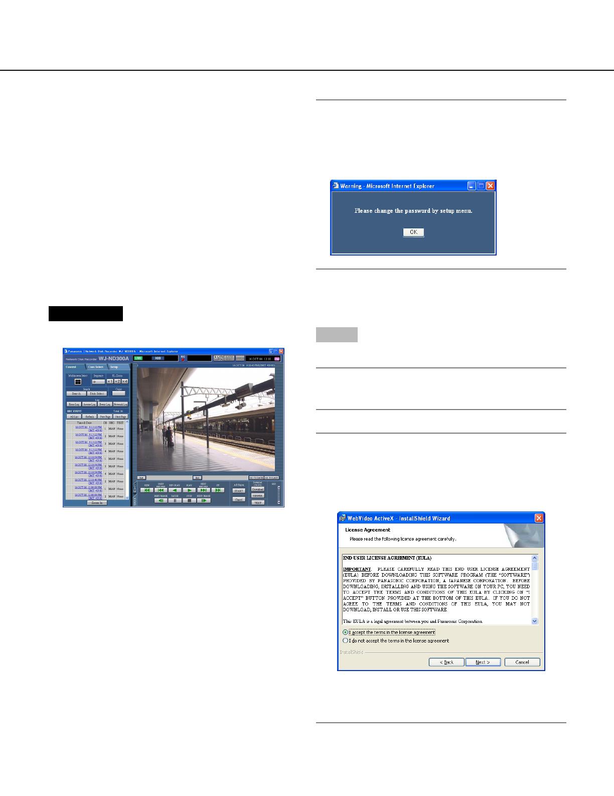
Screenshot 3
The top page will be displayed.
Step 3
Click the buttons or the tabs for operations.
Important:
If a message is displayed on the information bar,
see page 101.
Note:
When the top page is displayed for the first time, the
install wizard of the ActiveX control required to dis-
play images from the camera will be displayed.
Follow the instructions of the wizard.
• When the install wizard is displayed again even
after completing the installation of the ActiveX,
restart the PC.
Important:
When the unit is being operated without changing
the default administrator name and password, the
pop-up window saying that it is recommended to
change the password will be displayed.

16
About the Operation Window
[Control] tab
[Cam Select] tab
[Setup] tab Status display area Current time display area
Playback image
display area
Time and date of the
selected camera
Playback point
operation area
[HDD] tab
[CAM] tab
Camera title
Top Page
[Control] tab (page 17)
This tab is for performing operations such as searching
for recorded pictures on an HDD and copying recorded
pictures into the copy area of the HDD. From this tab,
you can also perform the functions of the camera pic-
ture switcher such as changing the display of camera
live pictures to quad or sequence display. Search
results or log information will also be displayed on this
page.
[Cam Select] tab (page 18)
The switcher functions such as switching camera chan-
nels are operable on this page.
[Setup] tab (pages 19 and 20)
Operations for setup of this unit can be performed on
this tab. Using the setup menu (Quick) and the setup
menu (Advanced)
Status display area (Page 21)
Current status such as playback status or recording sta-
tus will be displayed.
Current time display area
Current time will be displayed.
Playback image display area
Recorded images and live images will be displayed. The
setup menu will be displayed while setting up.
The camera title is displayed at the top left of the picture
and the time (current camera time for live pictures and
recorded time for recorded pictures) at the top right.
Clicking the camera title during quad display will display
the clicked picture on a single screen.
Playback point operations area (page 23)
It is possible to mark playback points or skip to the lat-
est recorded image.
[HDD] tab (page 23)
Operation for recorded images such as playback or
downloading (saving) recorded images can be per-
formed on this page.
[CAM] tab (page 25)
Perform the camera operations such as zooming, focus-
ing, auto functions, etc. on this panel.

17
[Control] Tab
[Multiscreen Select] box
Up to 4 camera images can be displayed simultaneous-
ly on a 4-Screen.
Each time the button is clicked, the camera picture is
changed to quad display according to the settings made
in [System] – [Basic Setup] – [Monitor Display] of the
setup menu (Advanced).
[Sequence] box
Camera images to be displayed will be switched by
clicking this button. Camera images will be displayed
sequentially according to the settings performed in
advance.
The lamp on the button lights (green) during sequence
operation.
[EL-Zoom] box
Camera images will be displayed in the proportion of the
clicked zoom ratio button.
:1x :2x :4x
[Search] box
[Search] button: The recording event
search will be displayed. Use this button to search
the recorded images. (Refer to the Operating
Instructions (PDF).)
Search results will be displayed in list form in the log
display area. (Refer to the Operating Instructions
(PDF).)
[Disk Select] button: The disk select win-
dow will be displayed. Use this button to select a
disk to be played/searched. (Refer to the Operating
Instructions (PDF).)
[Copy] box
The copy window will be displayed by clicking this but-
ton. This window is used to copy recorded images into
the copy area of the HDD.
[Log] box
[Error Log] button: The error logs of this unit
will be displayed. Logs will be displayed in list form
in the log display area.
[Access Log] button: The time when logged
in/out for this unit, the user ID, and the IP address
will be displayed.
Logs will be displayed in list form in the log display
area.
[Event Log] button: The event logs (event
occurrence times and their details) will be displayed.
Logs will be displayed in list form in the log display
area.
[Network Log] button: The network error logs
will be displayed.
Logs will be displayed in list form in the log display
area.
[Zoom In]: Enlarges the live camera image
and playback picture.

18
[Cam Select] Tab
[Multiscreen Select] box
Multiscreen button:
Up to 4 camera images can be displayed simultaneous-
ly on a multi-screen.
Each time the button is clicked, the camera picture is
changed to quad display according to the settings made
in [System] – [Basic Setup] – [Monitor Display] of the
setup menu (Advanced).
[Sequence] box
Sequence button:
Camera images to be displayed will be switched by
clicking this button. Camera images will be displayed
sequentially according to the settings performed in
advance.
[EL-Zoom] box
Camera images will be displayed in the proportion of the
clicked zoom ratio button.
:1x :2x :4x
[Cam Select] box
Clicking the camera title will display a list of cameras
connected to the unit.
Images from the selected camera channel will be dis-
played on the image display area by clicking one of
camera names.
Group title
Camera title
19
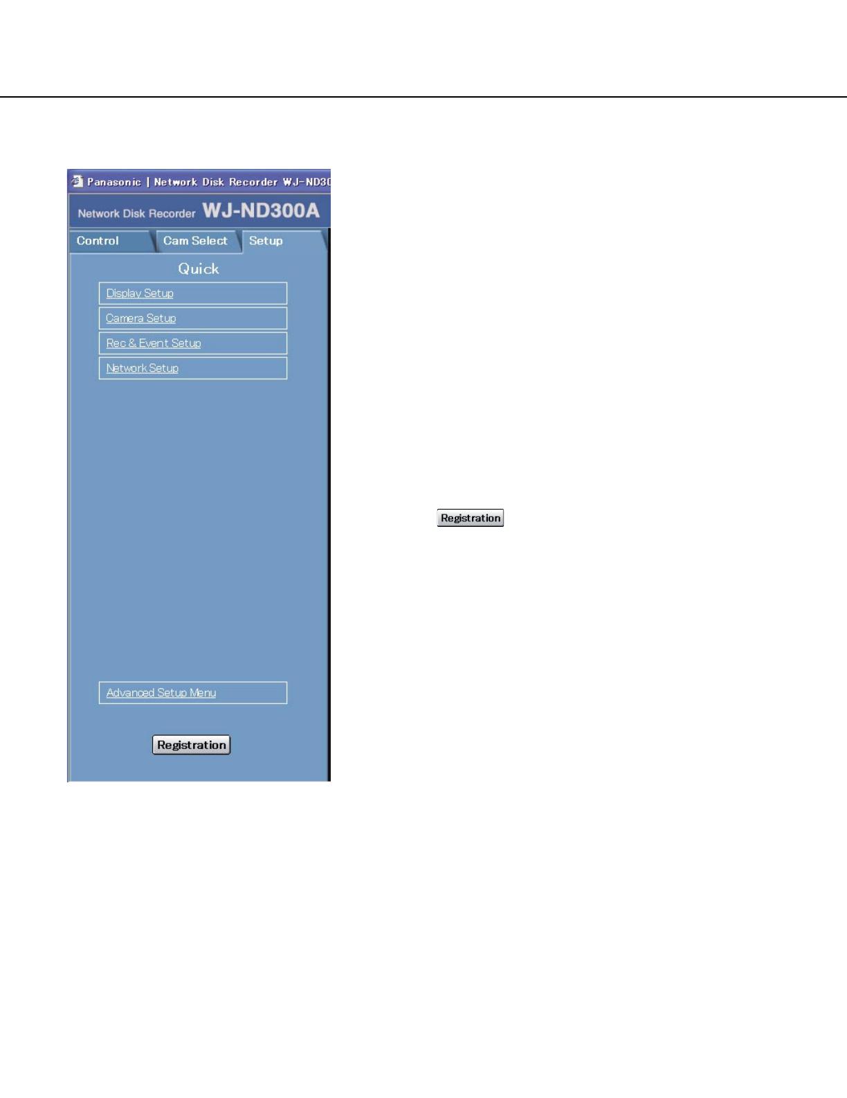
[Setup] Tab (Quick)
Display Setup
This button is for performing basic settings such as
date, time, and language display. Refer to page 28 for
further information.
Camera Setup
This button is for performing camera network settings
and group settings. Refer to page 30 for further informa-
tion.
Rec & Event Setup
Performs the basic settings for recording operation and
for event action. Refer to page 31 for further informa-
tion.
Network Setup
Settings for a network can be performed. Refer to page
35 for further information.
[Registration] button
Applies the settings to this unit. Click this button to com-
plete the setting after editing on the setup menu.

20
[Setup] Tab (Advanced)
Important:
When the settings are applied, all users who have
logged in to this unit will be forcibly logged out.
[System] button
The menu for the required system settings to activate
this unit will be displayed. Refer to page 42 for further
information.
[Recording] button
The menu for the recording settings will be displayed.
Perform the basic settings for recording and the settings
for emergency recording. Refer to page 46 for further
information.
[Event] button
Displays the setting menu for event actions of each
event type (site alarm, terminal alarm and command
alarm). Refer to page 49 for further information.
[Schedule] button
The menu for the settings of the recording schedule
(performs recording/event action by designating the
time and a day of the week) will be displayed. Refer to
page 53 for further information.
[Camera]
This button is for performing camera network settings,
group settings and sequence operation settings.
Refer to page 60 for further information.
[Comm] button
The menu for basic network settings will be displayed.
Refer to page 64 for further information.
[User Mng.] button
Displays a menu for registering user information. Refer
to page 75 for further information.
[Maintenance] button
The menu for the settings of the hard disk will be dis-
played. Refer to page 82 for further information.
[Registration] button
Applies the settings to this unit. Click this button to com-
plete the setting after editing on the setup menu.
Main menu
Submenu
/