Page is loading ...


~~=~e~E~E~:::~B~e~e~e~e~e~;;~=~=~?e~~e~:~:;';::;';:;';:;';:;';:;';:~J;';:;';:;';:;';e;';f;';e;';f;';:;';:;';;~"';"'~:"':"'~:""""':"'="'~"""'"
YOUR HEATHKIT gO-DAY LIMITED WARRANTY
Consumer Protection Plan for Heathkit Consumer Products
Welcome to the Heath family. We believe you will enjoy assembling your kit and will
be pleased with its performance. Please read this Consumer Protection Plan care·
fully. It is a "LIMITED WARRANTY" as defined in the U.S. Consumer Product
Warranty and Federal Trade Commission Improvement Act. This warranty gives
you specific legal rights, and you may also have other rights which vary from state to
state.
Heath's Responsibility
PARTS - Replacements for factory defective parts will be supplied free for 90 days from date of
purchase. Replacement parts are warranted for the remaining portion of the original warranty
period. You can obtain warranty parts direct from Heath Company by writing or telephoning us at
(616) 982~3571. And we will pay shipping charges to get those parts to you anywhere in the
world.
SERVICE LABOR - For a period of 90 days from the date of purchase, any maifunction caused
by defective parts or error in design will be corrected at no charge to you. You must deliv"'~ the unit
at your expense to the Heath factory, any Heathkit Electronic Center (units of Ver' '...'?LQ9Y
Electronics Corporation), or any of our authorized overseas distributors.
4
TECHNiCAL CONSULTATION - You will receive free consultation on any problem you might
encounter in the assembly or use of your Heathkit product. Just drop us a Une or give us a cail.
Sorry, we cannot accept collect calls.
NOT COVERED - The correction of assembly errors, adjustments, calibration, and damage due
to misuse, abuse, or negligence are not covered by the warranty. Use of corrosive solder and or
the unauthorized modification of the product or of any furnished component will void this warrai.ty
in its entirety. This warranty does not include reimbursement for inconvenience, loss of use,
customer assembly, set~up time, or unauthorized s~rvice.
This warranty covers only Heath products and is not extended to other equipment or components ~
that a customer uses in conjunction with our products.
SUCH REPAIR AND REPLACEMENT SHALL BE THE SOLE REMEDY OF THE CUSTOMER
AND THERE SHALL BE NO LIABILITY ON THE PART OF HEATH FOR ANY SPECIAL,
I
INDIRECT, INCIDENTAL OR CONSEQUENTIAL DAMAGES, INCLUDING BUT NOT LIMITED
TO ANY LOSS OF BUSINESS OR PROFITS, WHETHER OR NOT FORSEEABLE.
Some states do not allow the exclusion or limitation of incidental or consequential damages, sathe
above limitation or exclusion may not apply to you.
Owner's Responsibility
EFFECTIVE WARRANTY DATE - Warranty begins on the date of first consumer purchase You
must supply a copy of your proof of purchase when you request warranty service or parts.
ASSEMBLY _ Before seeking warranty service, you should complete the assembly by carefully
following the manual instructions. Heathkit service agencies cannot complete assembly and
adjustments that are customer's responsibility.
ACCESSORY EQUIPMENT - Performance malfunctions involving other non-Heath accessory
equipment, (antennas, audio components, computer peripherals and software, etc.) are not
covered by this warranty and are the owner's responsibility.
SHIPPING UNITS - Follow the packing instructions published in the assembly manuals. Dam~
age due to inadequate packing cannot be repaired under warranty.
If you are not satisfied with our service (warranty or otherwise) or our products, write
directly to our Director of Customer Service, Heath Company, Benton Harbor MI
49022. He will make certain your problems receive immedi~te, personal attention.
HEATH COMPANY PHONE DIRECTORY
The following telephone numbers are direct lines to the departments listed:
Kit orders and delivery Information. . .. (616) 982-3411
Credit .. . (616) 982-3561
Replacement Parts.. . . (616) 982-3571
Technical Assistance Phone Numbers
8:00 A.M. 10 12 P.M. and 1:00 P.M. to 4:30 P.M., EST, Weekdays Only
RiC, Audio, and Electronic Organs (616) 982-3310
Amateur Radio .... ., (616) 982-3298
Test Equipment,Weather Instruments and
Home Clocks ..
Television ..
Aircraft, Marine, Security, Scanners, Automotive,
Appliances and General Products
Computers.
.... " (616) 982-3315
. ... , (616) 982-3307

Heathkit® Manual
HF DUAL WATTMETER
HEATH COMPANY
BENTON HARBOR, MICHIGAN 49022
Copyright ©1979
Heath Company
All Rights Reserved
Printed in the United States of America

_pa_
9
_e_2 ._
In Case of Difficulty 32
Troubleshooting Chart 32
Step-by-Step Assembly 12
Circuit Board Assembly " 12

Page 3
~H£i------------------------------------------------------
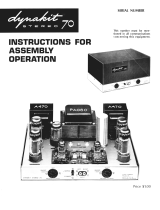
The HF Dual Wattmeter Model HM-2140 measures forward and reflected
power in transmission lines for frequencies between 1.8 and 30 MHz.
This Wattmeter was designed primarily for the Amateur Radio bands
within the high-frequency ranges on the 160, 80,40, 20, 15, and 10 meter
bands, and for other services which may lie in between the amateur bands.
The Wattmeter will measure transmissions: up to 200 and 2000 watts peak-
envelope-power in the forward direction and up to 500 watts reflected.
You can power the Wattmeter with a battery for complete portability, or
with the optional Heathkit Converter Model GRA-43-1where AC power is
available. No additional plug-in modules are required to cover the power or
frequency ranges. The Wattmeter is housed in a small, attractive, readily
portable cabinet.
A special switching circuit permits you to observe the battery condition at
any time. The remote sensor can be mounted into the cabinet or up to four
feet away from the metering cabinet and nearer to the transmitter's output
cables.
If you use only the 9-volt battery to power the Wattmeter, you must pur-
chase it separately. See Page 11 for additional details.

_pa_g_e_4 ~
IMPORTANT: Before you begin to assemble this kit, be sure to read the
information in the "Kit Builder's Guide."
When you perform the steps in the circuit board Pictorials, position
each part as shown. Follow the instructions carefully and read the
entire step before you perform each operation.
Capacitors will be called out by their capacitance value in pl
(picofarads) or
f-LF
(microfarads) and type.
Each circuit part in an electronic kit has its own component numbe
(R2,C4,etc.). Use these numbers when you want to identify the saffil
part in the various sections ofthe Manual. These numbers, which arl
especially useful if a part has to be replaced, appear:
Due to the small foil area around some ofthe circuit board holes and
the small area between the foils, use the utmost care to prevent solder
bridges between adjacent foils. Use only a minimum amount of
solder and small tip soldering iron of not over 40 watts. Allow the
iron to reach operating temperature; then apply it only long enough
to make a good solder connection. If you think a solder bridge may
exist, but you are not sure, compare the foil on the circuit board with
the "Circuit Board X-Ray View" in the "Illustration Booklet."
Most kits use a separate "Illustration Booklet" that contains illustration
(Pictorials, Details, etc.) that are too large for the Assembly Manual. Kee
the "Illustration Booklet" with the Assembly Manual. The illustrations in
i
are arranged in Pictorial number sequence.
SAFETY WARNING: Avoid eye injury when you clip off excess lea
lengths. Hold the leads so they cannot fly toward your eyes.
~lIIIIIiiiiiiiiiiiiiiiiiiiiiiiiiiiiiiiiiiiiiiiiiiiiiiiiiiiiiiiiiiiiiiiiiiiiiiiiiiiiiiiiiiiiiiiiiiiiiiiiiiiiiiiiiiiiiiiiiiiiiii-_-------- _
To eliminate a solder bridge; hold the circuit board above the solder-
ing iron and reheat the solder. As the solder melts; it will flow down
the iron.
If your work surface is smooth, place the circuit board on a cloth to
prevent it from sliding around when you solder component leads to
the foil.
Resistors will be called out by their resistance value inn (ohms) or in
ill
(1000 ohms).

Page 5
---------------------
Unpack the kit and check each part against the following list. Any part that
is packed in an individual envelope with the part number on it should be
placed back in the envelope after you identify it until all parts are accounted
for.
The key numbers correspond to the numbers on the "Parts Pictorial" in the
separate "Illustration Booklet" on Page 1.
Each circuit part in this kit has its own "Circuit Component Number" (R1,
CZ,D101, etc.J..This is a specific number for only that one part. The purpose
ofthese numbers is to help you identify the same part in each section ofthe
Manual.
To order a replacement part: Always include the PART NUMBER. Use the
Parts Order Form furnished with the kit. If one is not available, see "Re-
placement Parts" inside the rear cover of the Manual. Your Warranty is
located inside the front cover. For prices, refer to the s~parate "Heath Parts
Price List."
KEY
HEATH
No. Part No. CIRCUIT
Compo No.
NOTE: The following resistors are 1/4-watt, 5% tolerance unless otherwise
noted.
KEY
HEATH
No. Part No. CIRCUIT
Compo No.
4 560
n
(green-blue-brown)
2 1000
n
(brown-black-red)
6-561-12
6-102-12 R2, R4, R8,R9
R18, R22

_p_ag_e_6
I~
KEY HEATH QTY. DESCRIPTION
No. Part No. CIRCUIT
Camp. No. KEY HEATH QTY. DESCRIPTION
No. Part No.
A1 6-103-12 210 kG (brown-black-orange) R7, R11
A1 6-153-12 215 kG (brown-green-orange) R19, R21
A1 6-473-12 2 47 kG (yellow-violet-orange) R12, R16
A1 6-563-12 156 kG (green-blue-orange) R6
A1 6-334-12 2330 kG (orange-orange- R15, R17
yellow)
Precision Resistors, 1% Tolerance
A2 6-1652-12 16.5 kG (brown-blue- R24
green-red)
A2 6-4022-12 40.2 kG (yellow-black- R23
red-red)
82 25-885
83 27-136
83 27-137
2 100 fLF electrolytic
1 .015 fLF Mylar*
1 .02 fLF Mylar*
CIRCUIT
Camp. No.
C5, C6
C17
C18
NOTE: Integrated circuits may be marked for identification in any of the
following four ways:
2. Type number. (This refers only to the numbers; the letters may be
different or missing.)
C1, C2, C3,
C4,C7, C8
C9, C11, C12,
C13, C14, C15,
C16

_,--------------------------p-a-g
e-7
KEY HEATH QTY. DESCRIPTION
No. Part No. KEY HEATH QTY. DESCRIPTION
No. Part No.
01 90-1223-1
02 90-1224-1
03 203-1919-1
04 205-1588
05 261-34
1 Cabinet top
1 Cabinet bottom
1 Front panel
2 Side trim
4 Foot
E4 250-432 46-32 x 5/16" truss head screw
E5 250-89 1 6-32 x 3/8" screw
E6 250-347 2#6 x 1" sheet-metal screws
E7 252-3 96-32 nut
E8 253-21 4#6 flat washer
E9 253-89 1 #60-washer
E10 254-1 9 #610ckwasher
NOTE: Hardware packets may be marked to show the size of the hardware
they contain (HOW #6, for example). You may have to open more than one
packet to locate all the hardware. The hardware is shown actual size in the
Parts Pictorial.
E1 250-56
E2 250-365
E3 250-1157
4 6-32 x 1/4" screw
2 #6 x 1/4" hex head screw
4 1/4" circuit board spacer
F1 250-49
F2 252-1
F3 252-7
F4 253-10
F5 254-4
F6 254-7
2 3-48 x 1/4" screw
2 3-48 nut
1 Control nut
1 Control flat washer
1 Control lockwasher
2 #3 lockwasher

_pa_g
e_8 _
KEY HEATH QTY. DESCRIPTION
No. Part No. CIRCUIT
Compo No. KEY HEATH QTY. DESCRIPTION
No. Part No. CIRCUIT
Compo No.
G1 10-390 4 20 k11control R3, R5, R13, R14 H5 436-49 Power jack J1
G2 19-739 1250 k11control with switch R1/SW5 H6 455-633 Knob bushing
G3 64-62 12-section switch SW3, SW4 H7 462-932 Knob
G4 64-870 12-section switch SW1, SW2 H8 490-5 Nut starter
85-2039-1 1 Switch circuit board Solder
G5 407-741 1 Forward power meter M2
G5 407-742 1Reflected power meter M1 Printed Material
MISCELLANEOUS Blue and white label
390-1524 "Operation" label
H1 205-778 Alignment tool blade 597-260 Parts Order Form
H2 207-5 Cable clamp 597-308 Kit Builders Guide
H3 208-42 Battery holder Assembly Manual
H4 432-798 Battery clip (See title page for
part number.)

Page 9
~--------------------
Remote Sensor Assembly
(#100- 1749)
The Remote Sensor Assembly is a sealed unit which contains the following
parts. This Assembly has been factory tested and aligned. CAUTION: Do
KEY HEATH QTY. DESCRIPTION
No. Part No. CIRCUIT
Compo No.
6-470-12
6-332-12
6-223-12
6-104-12
10-312
10-390
10-941
47 il (yellow-violet-brown)
3300 il (orange-orange-red)
22 kil (red-red-orange)
100 kil (brown-black-yellow)
R101, R102
R103
X102
X103
not break the seal on the Remote Sensor Assembly; to do so may void the
warranty.
KEY HEATH QTY. DESCRIPTION
No. Part No. CIRCUIT
Compo No.
1 10 kil
1 20 kil
2 100 kil
R104
R107
R105, R106
CAPACITORS
20-103 2150 pF mica C101, C102
20-172 2 .001 f.LF(1000 pF) mica C103, C104
27-212 2 .0082 f.LFMylar C106, C107
31-8 1 1-8 pF trimmer C105
HARDWARE
250-324 26-32 x 3/16" screw
250-475 6 #6 x 3/8" hex head screw

_pa_g_e_10 ,~
KEY HEATH QTY. DESCRIPTION
No. Part No.
253-1 1 #6 fiber flat washer
254-1 12 #6 lockwasher
257-12 1 #6 brass eyelet
259-6 2#6 solder lug
256-5 8Long rivet
256-8 2 Short rivet
40-1970
56-20 1 Toroid coil
2 1N295 diode
OY.y,%1
l'
i8I 3(8
I
5i8I 7(8
I
iiiilii"1
i
I
j
o
5
1 (eM) 2
I
I
I
I II'
3 4
CIRCUIT
Compo No.
L101
D101, D102
2
I "
I
5
I
I ,
I '
6
3
, I
I
II
8
KEY HEATH QTY. DESCRIPTION
No. Part No.
75-30 1 Strain relief
85-2038-1 1 Printed circuit board
204-9 2 Angle bracket
214-215 1 Cover
214-216 1 Chassis
340-3 6" Bare wire
346-21 6" Sleeving
347-39 60" 5-wire cable
390-1505. 1Label seal
436-5 2 Coaxial jack
475-10 2 Ferrite bead
I
I ,
i
I
9
5
"I I
I"
13
I ,
I
I
i
14
I ,
I ,
I
I ' I
11 12
CIRCUIT
Compo No.
J101, J102
X101, X104

Page 11
~--------------------
Eveready #216 or # 1222
Mallory #M1604
Mallory #TR-146X (long life)
Burgess #2V6
ReA #VS323
Hellesens #410
Varta #438
The separate "Illustration Booklet" contains numbered illustrations (Picto-
rials, Details, etc.) that are too large for the Assembly Manual. The step-by-
step assembly instructions will direct you to the proper illustration in the
Booklet. After you have completed the assembly of your kit, place the
Illustration Booklet with the Manual and save them for future reference.

_pa_g_e_12 ,~
NOTE:To prepare a wire, cut it to the length indicated and remove 1/4"
0
insulation from each wire end. Tightly twist the bare wire ends and add
i
small amount of solder to hold the fine strands together.
r )
Locate the remote sensor and cable. Cut the cable 12"from the free
wire ends. Pull each ofthe wires from the 12"length ofthe cable; then
discard the
12"
white wire and the outer insulation. The remaining
four wires will be used during the Meter assembly.
( ) Locate the circuit board and position it lettered side up as shown ir
Pictorial i-ion the next page. Then install the parts as directed in th(
steps.
0
y.;
'h
%
1
(INCHES)
2
3
4
5
6
7
1
1{8 I 3:8
I
5{a!
7(8
I
,
I
I
I
I
IiI
I
i
I
I
Ii
I
Ii
I
I
,
I
I
i
I
I
I
i
I
!
I
I
I
I
i
,
I
I
f'Pilljl'l
i
I
i
iIiI
i
i
I
I
I
i
i
I
i
i
I
i
III
05
1
(eM)
23
•
5
6 8
9
10 11 12 13
,.
15 16 17

START.
NOTE: When you install a diode, always match
the band on the diode with the band mark on the
circuit board. A DIODEWILLNOT WORKIF IT
ISINSTALLEDBACKWARDS.SeeDetaill-1A.
<;iH\m'i;)A~~JD
Dl:
lN4149
diode #56-56).
(tI)
Solder the leads to the foil and cut offthe
excess lead lengths.
Page 13
IMPORTANT: TRE BANDED ERD OF DIDOES
C~R
BE MARKED IN A NUMBER OF
W~YS.
,~
v
Prepare a 2-1/2" black wire. Connect this
wire between the two
"H"
holes as
shown.
(~'" R7: 10 kD.(brown-black-orange).
R6: 56 kD.(green-blue-orange).
(...(' Solder the leads to the foil and cut offthe
excess lead lengths.

R18: 1000 il (brown-black-red).
Wrapthe leads ofa .02
iLF
Mylar capacitor
around the leads of a 16.5 kil (brown-
blue-green-red) precision resistor. Solder
the leads and cut off the excess capacitor
lead lengths. See Detail 1-2B.
R24/C18: Resistor/capacitor combina-
tion.
Similarly, wrap the leads of a .015
iLF
Mylar capacitor around the leads ofa40.2
kil (yellow-black-red-red) precision re-
sistor. Solder the leads and cut off the
excess capacitor lead lengths.
R23/C17: Resistor/capacitor combina-
tion.
R15: 330 ill (orange-orange-yellow).
R16: 47 ill (yellow-violet-orange).
R12: 47 ill (yellow-violet-orange).
Solder the leads to the foil and cut offthe
excess lead lengths.
Refer to Detaill-2A and locate pin 1 of the Ie.
Then install the Ie so pin 1 is inserted into hole
1 on the circuit board. Make sure all of the IC
pins go through the circuit board before you
solder the pins to the foiL

~, pa_g_e_15
NOTE:When you install ceramic capacitors, do
not push the insulated portions ofthe leads into
the circuit board holes. This could make it dif-
ficult to solder the leads to the foil.
n;ULATION
==fT==
Solder the leads to the foil and cut off the
excess lead lengths.
Jl:
Mount the power jack (#436-49)
firmly down onto the circuit board as
shown. Then solder its lugs to the foil.
~
<M\%~
Solder the leads to the foil and cut offthe
excess lead lengths.

Page 16 --------
----------------_...--I~
SW3/SW4: Push the 2-section switch
(#64-62) firmly down onto the circuit
board as shown. Be sure the switch as-
sembly is all the way down; then solder
its 12 lugs to the foil.
Mount the battery holder with two 3-48 x
1/4"screws, two #3lockwashers, and two
3-48 nuts as shown. Use the plastic nut
starter to hold and start 3-48 and 6-32
nuts.
f~
®
(vi
R13: 20 kl1 control (#10-390). Push the
control firmly down onto the board; then
solder the lugs to the foil.

Page 17
~I -----------------
START.
NOTE: As you install each component in this
column, be sure it is fully seated onto the circuit
board; then solder its lugs to the foil.
R1/SW5: 250 kO control with switch
(#19-739). Mount the switch as shown.
NOTE: Be sure the switch stands verti-
cally from the board .
." ,d.
'l
'f- "".
CONTIN UEQ
NOTE: Before you install an electrolytic
capacitor, note the position ofthe identified
(+
or -) lead, Be sure you connect the positive (
+)
lead to the positive
(+)
marked point on the
circuit board.
IDENTIFIED
LEA D IS
NEGATIVE (-)
IDENTIFIED
LEA D IS
POSITIVE
(+)
(~Solder the leads to the foil and cut offthe
excess lead lengths,

Page 19
~--------------------
Ref~rto Pictorial 1-7 (Illustration Booklet, Page 4) for the following steps.
(~ Position the circuit board assembly on your work area as shown in the
Pictorial.
2" red
1-1/2" red
1-3/4" red
3-1/2" red
2-1/4" black
2-1/4" black
7" green
7-1/2" brown
NOTE: In the following steps, when you connect a wire to a circuit board
hol\?, solder the wire to the foil and cut off any 'excess wire length.
(",I
Connect a 2" red wire to circuit board hole B. The free end will be
connected later.
NOTE: In the following steps, (NS) means not to solder because other wires
will be added later. "S-" with a number, such as "S-2" means to solder the
connection; the number following the "S" tells how many wires are at the
connection. When a wire passes through one connection and goes to
another, the "through" connection will be counted as two wires in the
solder note, one entering and one leaving the connection.
o
'Yo Yo
%
1
l'
(8 I 3;8
I
5(8 I 7;8
I
fl(1111111
I
I
I
o
5 1 (eM) 2
3
I
'I
,
8
2
I "
1
5
,I.
I '
5
(v('
Connect a 1-1/2"red wire from circuit board hole Cto switch SW5lug
1 (S-l).
(j"connect a 1-3/4"red wire from circuit board hole D to switch SW5lug
4 (S-l).
/
(\A'
Remove an additional 1/2"ofinsulation from one end ofthe 3-1/2"red
wire. Pass this end of the wire through switch SW5 lug 2 (S-2) and
connect the wire end to lug 3 (S-l). The free end of the wire will be
connected later.
(J
Connect a 2-1/4"black wire to circuit board hole A. The free wire end
will be connected later.
Connect a 2-1/4" black wire to circuit board hole E. The free wire end
will be connected later.
NOTE:The brown and green wires you will install in the next two steps are
jumper wires. Besure to route these wires exactly as shown in the Pictorial.
(..) Connect one end of a 7" green wire to circuit board hole
J
(between
switches SW3 and SW4) (S-l). Route the wire upward, forward, and
then across the board under control switch R1/SW5. Then route the
wire to the rear and connect the end to the other circuit board hole
J
(S-l).
, I ,
, I
9
5
I
"I I
I
12 13
6
,I 'I
I
15
I ,
I
, I
14
I ,
I
I
I
11
/