Page is loading ...

McCANNALOK SERIES
HIGH PERFORMANCE BUTTERFLY VALVE
Installation, Operation and Maintenance Manual
ASME Pressure Class
BRAY.COM THE HIGH PERFORMANCE COMPANY

McCANNALOK SERIES
Installation, Operation and Maintenance Manual
© 2022 BRAY INTERNATIONAL, INC. ALL RIGHTS RESERVED. BRAY.COM The Information
contained herein shall not be copied, transferred, conveyed, or displayed in any manner that would
violate its proprietary nature without the express written permission of Bray International, Inc.
2 of 36
For information on this product and other Bray products please visit us at our web page - www.bray.com.
Table of Contents
1.0 Definition of Terms 3
2.0 Introduction 4
3.0 Parts Diagram - Standard McCannalok and High Cycle McCannalok 5
4.0 Parts Diagram - Metal Seated McCannalok 6
5.0 Parts Diagram - Fire Safe McCannalok 7
6.0 Handling Requirements 8
7.0 Long Term Storage 9
8.0 Installation 10
9.0 Stem Seal Replacement 11
10.0 Seat Replacement 13
11.0 Disc and Stem Replacement 14
12.0 Special Instructions for McCannalok Fire Safe and Metal Seated Installation 17
13.0 Stem Seal Replacement - Fire Safe and Metal Seated 18
14.0 Seat Replacement - Fire Safe and Metal Seated 19
15.0 Disc and Stem Replacement - Fire Safe and Metal Seated 21
16.0 Special Instructions for McCannalok High Cycle Option Installation 22
17.0 Field Adjustments - All Valves 23
18.0 Maintenance 25
APPENDIX A - Tables 26

McCANNALOK SERIES
Installation, Operation and Maintenance Manual
© 2022 BRAY INTERNATIONAL, INC. ALL RIGHTS RESERVED. BRAY.COM The Information
contained herein shall not be copied, transferred, conveyed, or displayed in any manner that would
violate its proprietary nature without the express written permission of Bray International, Inc.
3 of 36
READ AND FOLLOW THESE INSTRUCTIONS CAREFULLY.
SAVE THIS MANUAL FOR LATER USE.
1.0 DEFINITION OF TERMS
WARNING
Indicates a potentially hazardous situation which, if not avoided, could result in
death or serious injury.
CAUTION
Indicates a potentially hazardous situation which, if not avoided, may result in
minor or moderate injury.
NOTICE
Used without the safety alert symbol, indicates a potential situation which, if not
avoided, may result in an undesirable result or state, including property damage.

McCANNALOK SERIES
Installation, Operation and Maintenance Manual
© 2022 BRAY INTERNATIONAL, INC. ALL RIGHTS RESERVED. BRAY.COM The Information
contained herein shall not be copied, transferred, conveyed, or displayed in any manner that would
violate its proprietary nature without the express written permission of Bray International, Inc.
4 of 36
2.0 INTRODUCTION
2.1 The McCannalok high performance butterfly valve combines the
advantages of trunnion type ball valves with the easy operation, light
weight and low cost of butterfly valves. One basic design is suitable for
a wide range of services, including oxygen, hydrogen, chlorine, sour gas,
vacuum and steam applications.
2.2 Features Include:
Bubble tight shutoff provided throughout a wide range of operating
conditions.
Suitable for both modulating and on/off services, the McCannalok butterfly
valve is easily automated with your choice of manual operators, electric
and pneumatic actuators, positioners and controls.
The McCannalok is available in a Fire Safe model qualified to API 607 and
BS 6755 Part 2.
The McCannalok is also available in a Metal Seated model providing IEC
60534-4 Class IV bidirectional leakage rates through full pressure range.
The McCannalok High Cycle configuration provides longer service life
than the standard McCannalok valve and is suitable for applications
including hydrogen, nitrogen, water, and other clean medias. High cycle
performance is dependent on process temperature, pressure, and line
media.
2.3 For additional information about McCannalok butterfly valves – including
application data, engineering specifications and actuator selection visit
www.bray.com or contact your Bray distributor or sales representative.
For additional information on certification documentation (PED, CE, etc.)
please visit www.bray.com or contact your local Bray sales representative.

McCANNALOK SERIES
Installation, Operation and Maintenance Manual
© 2022 BRAY INTERNATIONAL, INC. ALL RIGHTS RESERVED. BRAY.COM The Information
contained herein shall not be copied, transferred, conveyed, or displayed in any manner that would
violate its proprietary nature without the express written permission of Bray International, Inc.
5 of 36
3
10
16
12
11
17
15
14
19
20
18
25
23
5
22
9
13
2
1
8
47
6a
8
24
21
6b
26
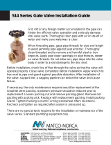
No. Description
1. Body
2. Disc
3. Stem
4. Soft Seat
5. Seat Retainer
6a. Locating Plug
6b. Bottom Plate
7. Gasket
8. Bearing
9. Disc Spacer
10. Drive Screw
11. Identification Tag
12. Thrust Washer
13. Stem Seal Set
14. Grounding Washer (optional)
15. Stud
16. Gland Ring
17. Retaining Ring
18. Gland Retainer
19. Gland Lock Washer or Belleville
Washer
20. Gland Hex Nut
21. Mounting Bracket
22. Cap Screw
23. Taper Pin
24. Lock Washer
25. Cap Screw
26. Cap Screw
3.0 PARTS DIAGRAM - STANDARD MCCANNALOK AND HIGH CYCLE MCCANNALOK

McCANNALOK SERIES
Installation, Operation and Maintenance Manual
© 2022 BRAY INTERNATIONAL, INC. ALL RIGHTS RESERVED. BRAY.COM The Information
contained herein shall not be copied, transferred, conveyed, or displayed in any manner that would
violate its proprietary nature without the express written permission of Bray International, Inc.
6 of 36
21
8
10
16
13b13a
12
11
17
15
14
19
20
3
23
1
8
7
6a
2
26
5
22
9
27
27
28*
29*
30*
18
24
25
6b
31
4.0 PARTS DIAGRAM - METAL SEATED MCCANNALOK
No. Description
1. Body
2. Disc
3. Stem
5. Seat Retainer
6a. Locating Plug
6b. Bottom Plate
7. Gasket
8. Bearing
9. Disc Spacer
10. Drive Screw
11. Identification Tag
12. Thrust Washer
13a. Stem Seal Set
13b. Alt. Stem Seal Set
14. Grounding Washer
15. Stud
16. Gland Ring
17. Retaining Ring
18. Gland Retainer
19. Lock Washer
20. Hex Nut
21. Mounting Bracket
22. Cap Screw
23. Taper Pin
24. Lock Washer
25. Cap Screw
26. Metal Seat
27. Metal Seat Gasket
28.* High Temperature Mounting
Bracket
29.* Stem Extension
30.* Drive Screw
31. Cap Screw
*Optional mounting for high temperature applications

McCANNALOK SERIES
Installation, Operation and Maintenance Manual
© 2022 BRAY INTERNATIONAL, INC. ALL RIGHTS RESERVED. BRAY.COM The Information
contained herein shall not be copied, transferred, conveyed, or displayed in any manner that would
violate its proprietary nature without the express written permission of Bray International, Inc.
7 of 36
5.0 PARTS DIAGRAM - FIRE SAFE MCCANNALOK
21
8
10
16
13
12
11
17
15
14
19
20
3
23
1
8
7
6a
2
26
27
4
27
5
22
9
18
25
24
6b
31
No. Description
1. Body
2. Disc
3. Stem
4. Soft Seat
5. Seat Retainer
6a. Locating Plug
6b. Bottom Plate
7. Gasket
8. Bearing
9. Disc Spacer
10. Drive Screw
11. Identification Tag
12. Thrust Washer
13. Stem Seal Set
14. Grounding Washer
15. Stud
16. Gland Ring
17. Retaining Ring
18. Gland Retainer
19. Lock Washer
20. Hex Nut
21. Mounting Bracket
22. Cap Screw
23. Taper Pin
24. Lock Washer
25. Cap Screw
26. Metal Seat
27. Metal Seat Gasket
31. Cap Screw

McCANNALOK SERIES
Installation, Operation and Maintenance Manual
© 2022 BRAY INTERNATIONAL, INC. ALL RIGHTS RESERVED. BRAY.COM The Information
contained herein shall not be copied, transferred, conveyed, or displayed in any manner that would
violate its proprietary nature without the express written permission of Bray International, Inc.
8 of 36
6.0 HANDLING REQUIREMENTS
6.1 Packed Valves
6.1.1 Crates: Lifting and handling of the packed valves in crates will be carried
out by a fork lift truck, by means of the appropriate fork hitches.
6.1.2 Cases: The lifting of packed valves in cases will be carried out in the
lifting points and in the center of gravity position which has been marked.
The transportation of all packed material must be carried out safely and
following the local safety regulations.
6.2 Unpacked Valves
6.2.1 Lifting and handling of valves should be carried out by using appropriate
means and observing the carrying limits. Handling must be carried out on
pallets, protecting all machined surfaces to avoid any damage.
6.2.2 With large bore valves, rigging the load must be carried out by using the
appropriate tools to prevent the valve from falling or moving during the
lifting and handling.
CAUTION
For valve handling and/or lifting, the lifting equipment (fasteners, hooks, etc.)
must be sized and selected while taking into account the valve weight indicated
in our packing list and/or delivery note. Lifting and handling must be made only
by qualified personnel.
Fasteners must be protected by plastic covers in sharp corner areas.
Caution must be taken during the handling to avoid this equipment passing
over workers or over any other place where a possible fall could cause injury or
damage. In any case, local safety regulations must be respected

McCANNALOK SERIES
Installation, Operation and Maintenance Manual
© 2022 BRAY INTERNATIONAL, INC. ALL RIGHTS RESERVED. BRAY.COM The Information
contained herein shall not be copied, transferred, conveyed, or displayed in any manner that would
violate its proprietary nature without the express written permission of Bray International, Inc.
9 of 36
7.0 LONG TERM STORAGE
7.1 If valves are to be stored before installation, storage must be carried out
in a controlled manner as follows:
7.1.1 Valves must be stored in a closed, clean and dry environment.
7.1.2 Valve disc to be in closed position and the body end faces must be
covered with appropriate flange protection. Flange protectors should only
be removed at the time of installation.
7.1.3 Valves should be stored indoors with a preferred temperature range from
40°F (4°C) to 85°F (29°C).
7.1.4 The valves should be checked to ensure the above conditions are
maintained every three months.
7.2 These are general guidelines for valve storage. Please consult the factory
for information regarding specific requirements.

McCANNALOK SERIES
Installation, Operation and Maintenance Manual
© 2022 BRAY INTERNATIONAL, INC. ALL RIGHTS RESERVED. BRAY.COM The Information
contained herein shall not be copied, transferred, conveyed, or displayed in any manner that would
violate its proprietary nature without the express written permission of Bray International, Inc.
10 of 36
8.0 INSTALLATION
8.1 Special instructions for Fire Safe and Metal Seated valves appear in
Section 10.
8.2 The McCannalok valve is designed to be mounted between ANSI flanges.
When the valve is open, the disc (2) will extend into the pipe on both
sides of the valve (further on the body side than the seat retainer side of
the valve). Piping must be large enough to allow the disc (2) to clear the
pipe. Tables 1 and 2 show the minimum pipe ID allowable and standard
pipe IDs. In general, Class 150 valves will clear Schedule 40 pipe and Class
300 valves will clear Schedule 80 pipe. Class 600 will clear Schedule 80
pipe in sizes 3, 4 and 6 and Schedule 100 pipe in sizes 8, 10, 12, 14 and 16.
CAUTION
If handle or actuator has been removed do not rotate disc beyond full open or
closed position as this could cause damage to sealing surfaces.
8.3 NOTE: McCannalok valves are equipped with travel limiters to prevent
over closure. The valve is opened by turning the shaft counterclockwise,
closed by turning the shaft clockwise. The double “D” flats or keyway at
the top of the stem is parallel to the disc edge.
NOTICE
For maximum service life, install the valve with the seat retainer upstream.
Positive shutoff will be obtained with the valve in either position; however,
installation with the seat retainer upstream will give longer service life, especially
in erosive services.
8.4 With the disc (2) in the closed position, carefully center the valve
between the flanges. Guide holes (wafer pattern valve) or tapped holes
(lugged valves), which match the ANSI pipe flange holes assist in positive
alignment.
8.5 Use standard flange torques when bolting valve into the line. The seat is
sufficiently compressed by the seat retainer and additional force from
flange bolting is not required.
8.6 Gaskets should conform to the requirements of API 601 3rd Edition for
ASME B16.5 class flanges. Spiral wound gaskets, such as Flexitallic CG or
CGl series, conforming to ASME B16.20 are acceptable.

McCANNALOK SERIES
Installation, Operation and Maintenance Manual
© 2022 BRAY INTERNATIONAL, INC. ALL RIGHTS RESERVED. BRAY.COM The Information
contained herein shall not be copied, transferred, conveyed, or displayed in any manner that would
violate its proprietary nature without the express written permission of Bray International, Inc.
11 of 36
9.0 STEM SEAL REPLACEMENT
9.1 Refer to Standard McCannalok Parts Diagram for part identification.
NOTICE
Note assembly positions before removal.
9.2 If required, remove handle assembly. Remove socket head cap screws
(25) and lock washers (24). Remove mounting bracket (21). For actuated
valves, unbolt mounting bracket from body (1) and lift actuator assembly
off stem.
9.3 Remove gland retainer nuts (20) and lock washers (19). Remove gland
retainer (18) anti-blowout retaining ring or split ring (17) (depending on
size) and gland ring (16).
NOTICE
The Class 600 valves have stem seal sets located at the upper and lower portions
of the shaft. These instructions apply to both the upper and lower stem seals.
9.4 Remove the grounding washer (14) if present. Remove stem seals (13).
Do not remove thrust washer (12) unless further valve disassembly is
required.
CAUTION
When removing stem seals, care should be taken not to scratch stem or body
packing box bore.
9.5 Examine body packing box bore and stem, clean as necessary to remove
any corrosion or foreign matter before installing new stem seals.
9.6 Install new stem seals in body packing box one at a time, TFE (white)
stem seals first, with the carbon fiber ring at the top. Stagger stem seal
joints 180° apart when installing. Tamp each stem seal to bottom before
installing next stem seal. Table 3 shows the correct number of stem seals
to install in each valve.
NOTICE
On the larger valves it will be necessary to compress each stem seal before
adding the next.

McCANNALOK SERIES
Installation, Operation and Maintenance Manual
© 2022 BRAY INTERNATIONAL, INC. ALL RIGHTS RESERVED. BRAY.COM The Information
contained herein shall not be copied, transferred, conveyed, or displayed in any manner that would
violate its proprietary nature without the express written permission of Bray International, Inc.
12 of 36
9.7 Install a new grounding washer (14) if required. Slide gland ring (16)
over stem on top of seals (13). Install anti-blowout retaining ring or split
ring (17) (depending on valve size). Slide gland retainer (18) over stem
and onto gland studs (15). Place lockwashers (19) and hex nuts (20) on
studs (15) and tighten finger tight. Tighten gland nuts (20) evenly and
alternately to the proper torque value given in Table 4.
9.8 Remount actuator, or mounting bracket (21) with lock washers (24) and
cap screws (25), or handle assembly. Ensure that mounting bracket cap
screws are tightened to the correct torque per Table 7.
9.9 Operate valve open and closed several times to check for binding and to
set the stem seals. Loosen gland nuts (20) and retighten to torque value
given in Table 4.

McCANNALOK SERIES
Installation, Operation and Maintenance Manual
© 2022 BRAY INTERNATIONAL, INC. ALL RIGHTS RESERVED. BRAY.COM The Information
contained herein shall not be copied, transferred, conveyed, or displayed in any manner that would
violate its proprietary nature without the express written permission of Bray International, Inc.
13 of 36
10.0 SEAT REPLACEMENT
10.1 Refer to Standard McCannalok Parts Diagram for part identification.
10.2 With the disc (2) in the closed position, remove the valve from service.
10.3 Lay the valve down with the disc (2) in the closed position and the seat
retainer side facing up.
10.4 Remove the socket head cap screws (22), the seat retainer (5) and seat
(4).
10.5 Carefully clean the seat area in the body (1) and seat retainer. Remove
foreign material, dirt, etc. Check disc seating area for nicks or scratches.
10.6 With the disc (2) in the CLOSED position, place the new seat (4) on disc
(2), carefully centering it in the recess in the body (1).
CAUTION
Do not shift the retainer in order to align holes. It may shift the seat from its
correct position.
10.7 Align the holes in the seat retainer (5) with matching holes in body (1)
and carefully place in position on top of seat (4).
10.8 Lightly grease cap screw (22) threads and bearing areas.
10.8.1 Install the cap screws and tighten all cap screws finger tight.
10.8.2 Tighten the cap screws to approximately 30% of the torque value listed in
Table 4 in a crisscross pattern.
10.8.3 Repeat Step 2, increasing the torque value to approximately 60% of the
final torque value.
10.8.4 Repeat Step 3, increasing the torque value to the final required torque
value.
10.8.5 Open the disc (2). Re-torque all cap screws to the final required torque
value given in Table 4.
10.9 A final tightening should be performed/checked prior to installation.
Operate valve several times and examine seat for any damage before
reinstalling the valve in service.

McCANNALOK SERIES
Installation, Operation and Maintenance Manual
© 2022 BRAY INTERNATIONAL, INC. ALL RIGHTS RESERVED. BRAY.COM The Information
contained herein shall not be copied, transferred, conveyed, or displayed in any manner that would
violate its proprietary nature without the express written permission of Bray International, Inc.
14 of 36
11.0 DISC AND STEM REPLACEMENT
11.1 Refer to Standard McCannalok Parts Diagram for part identification.
NOTICE
Stem and disc are supplied as a matched set with taper pins and are to be
replaced as a set.
11.2 For handle-operated valves remove handle assembly. Remove socket
head cap screws (25) and lock washers (24). Remove mounting bracket
(21). For actuated valves, unbolt mounting bracket from body (1) and lift
actuator assembly off stem.
NOTICE
Note assembly positions before removal.
11.3 Remove gland retainer nuts (20) and lock washers (19). Remove gland
retainer (18), anti-blowout retaining ring or split ring (17) (depending on
valve size) and gland ring (16). Remove grounding washer (14) if present.
11.4 Remove stem seals (13).
CAUTION
Take care not to scratch stem or packing box bore.
11.5 Remove locating plug or bottom plate (6) and gasket (7).
11.6 Remove cap screws (22), seat retainer (5) and seat (4).
11.7 Turn disc (2) to the full open position and drill out tack welds on large end
of taper pins (23).
CAUTION
Take care to support valve so that disc surfaces are not scratched.
11.8 Drill sizes to remove tack welds as given in Table 5. Use center-punch to
dimple center of tack welds prior to drilling.
11.9 Place valve in flat position, with flat face of disc (2) up. Support disc (2)
and body (1) on wooden blocks to protect disc (2) and body (1) surfaces.
Disc (2) will rest in partially open position.

McCANNALOK SERIES
Installation, Operation and Maintenance Manual
© 2022 BRAY INTERNATIONAL, INC. ALL RIGHTS RESERVED. BRAY.COM The Information
contained herein shall not be copied, transferred, conveyed, or displayed in any manner that would
violate its proprietary nature without the express written permission of Bray International, Inc.
15 of 36
11.10 Knock out taper pins (23) using a rod or punch on small end of pin
(opposite tack weld). It may be necessary to lift body (1) and rotate disc
(2) slightly to do this. Make sure disc (2) is resting on wood block since
it will swing freely on stem with pins removed. When pins (23) are out,
lay body (1) down so disc (2) and body (1) are evenly supported on flat
surface.
11.11 Using a brass bar or drift punch, knock stem (3) loose and pull from body
(1). After long or severe service this may take considerable force.
CAUTION
Be careful not to damage bearings (8), spacers (9) or body (1).
11.12 Disc spacers (9) are used at top and bottom of disc (2) to properly
position disc (2) in body (1). Proper spacers were selected at initial
assembly and rarely require replacement. The location of these spacers
should be noted and the spacers marked at disassembly so that they are
reinstalled in the same positions, top and bottom.
11.13 Separate body (1) from disc (2) and remove thrust washer (12) from
packing bore.
11.14 Examine stem bearings (8) for excessive wear. If removed from body (1),
note position and mark to reinstall in same location. If bearing liner is
worn through to the shell, or severe damage is evident they should be
replaced. Replacement is rarely needed.
11.15 Clean body (1) thoroughly to remove all dirt, foreign matter, rust, etc.
11.16 Place the body (1) flat, seat retainer side up and support it on wooden
blocks sufficiently above the work surface as to facilitate insertion of the
new disc (2) in open position. Lower the disc (2) into position, aligning
the bores in body (1) and disc (2).
11.17 Insert new stem (3) in body (1) with large end of the taper pin holes
toward the top. Assemble disc spacers (9) as stem (3) is inserted, making
sure that spacers are returned to original locations as marked.
11.18 Align taper pin holes in disc (2) and stem and install taper pins (23). Drive
pins in tightly with rod or punch and tack weld each pin (23) to disc (2) at
large end of pin.
11.19 Install new gasket (7) on locating plug (6a) or bottom plate (6b) and
install plug or plate in body (1). See Table 7 for locating plug and bottom
plate torques.
11.20 Install new stem seals, following instructions in “Stem Seal Replacement”
section.
11.21 Install new seat, following instructions in “Seat Replacement” section.

McCANNALOK SERIES
Installation, Operation and Maintenance Manual
© 2022 BRAY INTERNATIONAL, INC. ALL RIGHTS RESERVED. BRAY.COM The Information
contained herein shall not be copied, transferred, conveyed, or displayed in any manner that would
violate its proprietary nature without the express written permission of Bray International, Inc.
16 of 36
11.22 Remount handle assembly or actuator and operate valve several times to
verify proper operation. Examine disc (2) and seat (4) for any damage
before reinstalling in line. Ensure mounting bracket cap screws (25) are
tightened to torques listed in Table 7.

McCANNALOK SERIES
Installation, Operation and Maintenance Manual
© 2022 BRAY INTERNATIONAL, INC. ALL RIGHTS RESERVED. BRAY.COM The Information
contained herein shall not be copied, transferred, conveyed, or displayed in any manner that would
violate its proprietary nature without the express written permission of Bray International, Inc.
17 of 36
12.0 SPECIAL INSTRUCTIONS FOR MCCANNALOK FIRE SAFE
AND METAL SEATED INSTALLATION
12.1 The McCannalok Fire Safe valve will provide fire safe shutoff with flow
in either direction, meeting API 607 and British Standard 6755 part
2 criteria, as well as bubble-tight shutoff in either direction in normal
service. However, installation with the seat retainer upstream provides
maximum protection to the soft seat and will increase seat life, especially
in erosive services.
12.2 The McCannalok Metal Seated valve has been extensively performance
tested in our state-of-the-art technology center and test laboratory. The
Inconel® 718 metal seat has been contoured to provide control, strength
and flexibility in high temperature applications.
12.3 Installation bolting information given for the standard McCannalok valves
is also applicable to the Fire Safe and Metal Seated versions.

McCANNALOK SERIES
Installation, Operation and Maintenance Manual
© 2022 BRAY INTERNATIONAL, INC. ALL RIGHTS RESERVED. BRAY.COM The Information
contained herein shall not be copied, transferred, conveyed, or displayed in any manner that would
violate its proprietary nature without the express written permission of Bray International, Inc.
18 of 36
13.0 STEM SEAL REPLACEMENT - FIRE SAFE AND METAL
SEATED
13.1 The procedure for stem seal replacement in Section 7 also applies to
Metal Seated valves that use TFE (white) seals. For Fire Safe and Metal
Seated valves that use graphite stem seals, use the following exceptions.
13.2 Graphite stem seals are used in the Fire Safe valves and as an option for
Metal Seated valves. The arrangement of the two types of stem seals
when installed is:
> bottom seal - carbon fiber braided ring
> center seals - graphite rings
> top seal - carbon fiber braided ring.
13.3 Table 3 shows graphite only stem seal quantities for class 150 and 300
valves.
13.4 Table 6 shows gland nut torques to be used for graphite only stem seal
sets.

McCANNALOK SERIES
Installation, Operation and Maintenance Manual
© 2022 BRAY INTERNATIONAL, INC. ALL RIGHTS RESERVED. BRAY.COM The Information
contained herein shall not be copied, transferred, conveyed, or displayed in any manner that would
violate its proprietary nature without the express written permission of Bray International, Inc.
19 of 36
14.0 SEAT REPLACEMENT - FIRE SAFE AND METAL SEATED
14.1 Fire Safe valves will have both a soft seat (4) and metal seat (26) while
the Metal Seated valves have only a metal seat (26). Ignore soft seat
instructions for Metal Seated valves.
14.2 With the disc (2) in the closed position, remove the valve from the line.
WARNING
Verify line is depressurized prior to removal.
14.3 Lay the valve down with the disc (2) in the closed position and the seat
retainer side facing up.
14.4 Remove socket head cap screws (22), seat retainer (5), metal seat (26),
gaskets (27) and soft seat (4).
14.5 Carefully remove graphite gaskets (27) from metal seat (26). Do
not bend or crimp metal seat. All traces of the old gaskets must be
removed.
14.6 Clean seat retainer (5) and body (1) surfaces to remove any adhering
gasket material, corrosion, or other foreign material. Examine disc (2)
seating surfaces for damage and examine seating surface of metal seat
and soft seat for wear or damage. Replace if damaged.
14.7 Place new soft seat (4) on disc (2), carefully centering in body (1)
recess.
CAUTION
Handle the graphite gaskets (27) carefully as they are thin and are easily torn or
scratched.
14.8 Place new graphite gasket (27) on the body (1). Position metal seat
(26) over the disc (2), lip facing out, on top of the soft seat (4). Place
another graphite gasket (27) on top of the metal seat. Graphite gaskets
can be first attached to the metal seat to simplify the assembly. Spray a
suitable adhesive, like 3M Super 77 general purpose adhesive or similar,
in 3 or 4 spots on both sides of the metal seat to hold the gaskets in
position.
CAUTION
Be careful that seat does not shift when retainer is installed.
14.9 Align holes in seat retainer (5) with holes in body (1) and seat and
carefully place seat retainer in position, on top of seat.
14.10 Lightly grease cap screw threads and bearing areas.

McCANNALOK SERIES
Installation, Operation and Maintenance Manual
© 2022 BRAY INTERNATIONAL, INC. ALL RIGHTS RESERVED. BRAY.COM The Information
contained herein shall not be copied, transferred, conveyed, or displayed in any manner that would
violate its proprietary nature without the express written permission of Bray International, Inc.
20 of 36
14.10.1 Step 1: Install the cap screws and tighten all cap screws finger tight.
14.10.2 Step 2: Tighten the cap screws to approximately 30% of the torque
value listed in Table 4 in a crisscross pattern.
14.10.3 Step 3: Repeat Step 2, increasing the torque value to approximately
60% of the final torque value.
14.10.4 Step 4: Repeat Step 3, increasing the torque value to the final required
torque value.
14.10.5 Step 5: Open the disc (2). Re-torque all cap screws to the final required
torque value given in Table 4.
14.11 Lubricate the disc (2) edge with molybdenum disulfide spray or similar
lubricant, if available. As a minimum, lubricate the disc edge with light
machine oil or light grease. Operate valve several times and examine
seat for damage before reinstalling in line.
/