Page is loading ...

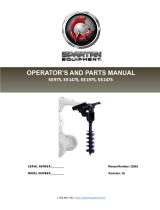
OPERATOR'S AND PARTS MANUAL
AUGER DRIVES
X900 High Speed
&
X1500 High Torque
SERIAL NUMBER: Manual Number: OM859
Part Number: 75759
MODEL NUMBER: Rev. 1
888-888-1085 I www.spartanequipment.com | Joppa, MD 21085, United States of America Copyright
©
M-2267 8-8-18-3


TABLE OF CONTENTS
AUGER DRIVES
PREFACE ...................................................................................................................................
3
SAFETY PRECAUTIONS
SAFETY STATEMENTS .................................................................................................................................. 5
GENERAL SAFETY PRECAUTIONS .......................................................................................................... 5-7
EQUIPMENT SAFETY PRECAUTIONS ...................................................................................................... 8-9
INSTALLATION & OPERATION
INSTALLING THE DRIVE UNIT .....................................................................................................................10
INSTALLING AN AUGER ......................................................................................................................... 10-11
OPERATION ............................................................................................................................................ 11-12
STORAGE ......................................................................................................................................................13
LIFT POINTS ..................................................................................................................................................13
TIE DOWN POINTS .......................................................................................................................................14
TRANSPORTING ...........................................................................................................................................14
MAINTENANCE
SEVICE INTERVALS ..................................................................................................................................... 15
CHECKING PLANETARY GEAR CASE OIL ................................................................................................. 15
CHANGING PLANETARY GEAR CASE OIL. ................................................................................................ 15
WEAR PARTS ................................................................................................................................................16
TROUBLESHOOTING ............................................................................................................... 17
LIMITED WARRANTY ..................................................................................................................... 19
PARTS
X900 HIGH SPEED AUGER DRIVE ........................................................................................................ 20-21
X1500 HIGH TORQUE AUGER DRIVE ................................................................................................... 22-23
M-2248 11-18-13
75759

THIS PAGE
IS INTENTIONALLY
BLANK
2
75759

PREFACE
GENERAL COMMENTS
Congratulations on the purchase of your new attachment! This product was carefully designed
and manufactured to give you many years of dependable service. Only minor maintenance (such as
cleaning and lubricating) is required to keep it in top working condition. Be sure to observe all
maintenance procedures and safety precautions in this manual and on any safety decals located on
the product and on any equipment on which the attachment is mounted.
This manual has been designed to help you do a better, safer job. Read this manual carefully
and become familiar with its contents.
WARNING!
Never let anyone operate this unit without reading the "Safety Precautions" and
"Operating Instructions" sections of this manual.
Always choose hard, level ground to park the vehicle on and set the brake so
the unit cannot roll.
Unless noted otherwise, right and left sides are determined from the operator's control position
when facing the attachment.
NOTE: The illustrations and data used in this manual were current (according to the infor-
mation available to us) at the time of printing, however, we reserve the right to redesign and
change the attachment as may be necessary without notification.
BEFORE OPERATION
The primary responsibility for safety with this equipment falls to the operator. Make sure the
equipment is operated only by trained individuals that have read and understand this manual. If there
is any portion of this manual or function you do not understand, contact your local authorized dealer or
the manufacturer to obtain further assistance. Keep this manual available for reference. Provide the
manual to any new owners and/or operators.
SAFETY ALERT SYMBOL
This is the "Safety Alert Symbol" used by this industry. This symbol is used to warn of
possible injury. Be sure to read all warnings carefully. They are included for your safety
and for the safety of others working with you.
SERVICE
Use only manufacturer replacement parts. Substitute parts may not meet the required stan-
dards. Record the model and serial number of your unit on the cover of this manual. The parts
department needs this information to insure that you receive the correct parts.
SOUND AND VIBRATION
Sound pressure levels and vibration data for this attachment are influenced by many different
parameters: some items are listed below (not inclusive):
prime mover type, age, condition, with or without cab enclosure and
configuration operator training, behavior, stress level
job site organization, working material condition, environment
Based on the uncertainty of the prime mover, operator, and job site, it is not possible to get precise
machine and operator sound pressure levels or vibration levels for this attachment.
75759
3

THIS PAGE
IS INTENTIONALLY
BLANK
4
75759

NOTICE
WARNING!
SAFETY STATEMENTS
THIS SYMBOL BY ITSELF OR WITH A WARNING WORD THROUGHOUT THIS
MANUAL IS USED TO CALL YOUR ATTENTION TO INSTRUCTIONS INVOLVING
YOUR PERSONAL SAFETY OR THE SAFETY OF OTHERS. FAILURE TO FOLLOW
THESE INSTRUCTIONS CAN RESULT IN INJURY OR DEATH.
THIS SIGNAL WORD INDICATES A HAZARDOUS SITUATION WHICH, IF
NOT AVOIDED, WILL RESULT IN DEATH OR SERIOUS INJURY.
THIS SIGNAL WORD INDICATES A HAZARDOUS SITUATION WHICH, IF
NOT AVOIDED, COULD RESULT IN DEATH OR SERIOUS INJURY.
THIS SIGNAL WORD INDICATES A HAZARDOUS SITUATION WHICH, IF
NOT AVOIDED, COULD RESULT IN MINOR OR MODERATE INJURY.
NOTICE IS USED TO ADDRESS PRACTICES NOT RELATED TO PHYSICAL
INJURY.
GENERAL SAFETY PRECAUTIONS
READ MANUAL PRIOR TO INSTALLATION
Improper installation, operation, or maintenance of this equipment could result in serious
injury or death. Operators and maintenance personnel should read this manual, as well
as all manuals related to this equipment and the prime mover thoroughly before
beginning installation, operation, or maintenance. FOLLOW ALL SAFETY
INSTRUCTIONS IN THIS MANUAL AND THE PRIME MOVER'S MANUAL(S).
READ AND UNDERSTAND ALL SAFETY STATEMENTS
Read all safety decals and safety statements in all manuals prior to operating or
working on this equipment. Know and obey all OSHA regulations, local laws, and other
professional guidelines for your operation. Know and follow good work practices when
assembling, maintaining, repairing, mounting, removing, or operating this equipment.
KNOW YOUR EQUIPMENT
Know your equipment's capabilities, dimensions, and operations before operating.
Visually inspect your equipment before you start, and never operate equipment that is
not in proper working order with all safety devices intact. Check all hardware to ensure
it is tight. Make certain that all locking pins, latches, and connection devices are
properly installed and secured. Remove and replace any damaged, fatigued, or
excessively worn parts. Make certain all safety decals are in place and are legible.
Keep decals clean, and replace them if they become worn or hard to read.
75759 5
M-806 7 -30-18-
3
WARNING
CAUTION
DANGER

1.
WARNING!
WARNING!
WARNING!
GENERAL SAFETY PRECAUTIONS
PROTECT AGAINST FLYING DEBRIS
Always wear proper safety glasses, goggles, or a face shield when driving pins in or
out, or when any operation causes dust, flying debris, or any other hazardous material.
LOWER OR SUPPORT RAISED EQUIPMENT
Do not work under raised booms without supporting them. Do not use support material
made of concrete blocks, logs, buckets, barrels, or any other material that could
suddenly collapse or shift positions. Make sure support material is solid, not decayed,
warped, twisted, or tapered. Lower booms to ground level or on blocks. Lower booms
and attachments to the ground before leaving the cab or operator's station.
USE CARE WITH HYDRAULIC FLUID PRESSURE
Hydraulic fluid under pressure can penetrate the skin and cause serious injury or
death. Hydraulic leaks under pressure may not be visible. Before connecting or dis-
connecting hydraulic hoses, read your prime mover's operator's manual for detailed
instructions on connecting and disconnecting hydraulic hoses or fittings.
Keep unprotected body parts, such as face, eyes, and arms as far away as
possible from a suspected leak. Flesh injected with hydraulic fluid may develop
gangrene or other permanent disabilities.
If injured by injected fluid, see a doctor at once. If your doctor is not familiar with
this type of injury, ask him or her to research it immediately to determine proper
treatment.
Wear safety glasses, protective clothing, and use a piece of cardboard or wood
when searching for hydraulic leaks. DO NOT USE YOUR HANDS! SEE ILLUS-
TRATION.
CARDBOARD
HYDRAULIC HOSE
OR FITTING
6
M-807 7 -30-18-3
75759

WARNING!
WARNING!
WARNING!
75759
GENERAL SAFETY PRECAUTIONS
DO NOT MODIFY MACHINE OR ATTACHMENTS
Modifications may weaken the integrity of the attachment and may impair the function,
safety, life, and performance of the attachment. When making repairs, use only the
manufacturer's genuine parts, following authorized instructions. Other parts may be
substandard in fit and quality. Never modify any ROPS (Roll Over Protection Structure)
or FOPS (Falling Object Protective Structure) equipment or device. Any modifications
must be authorized in writing by the manufacturer.
SAFELY MAINTAIN AND REPAIR EQUIPMENT
Do not wear loose clothing or any accessories that can catch in moving parts. If you
have long hair, cover or secure it so that it does not become entangled in the
equipment.
Work on a level surface in a well-lit area.
Use properly grounded electrical outlets and tools.
Use the correct tools for the job at hand. Make sure they are in good condition for
the task required.
Wear the protective equipment specified by the tool manufacturer.
SAFELY OPERATE EQUIPMENT
Do not operate equipment until you are completely trained by a qualified operator in
how to use the controls, know its capabilities, dimensions, and all safety requirements.
See your machine's manual for these instructions.
Keep all step plates, grab bars, pedals, and controls free of dirt, grease, debris,
and oil.
Never allow anyone to be around the equipment when it is operating.
Do not allow riders on the attachment or the prime mover.
Do not operate the equipment from anywhere other than the correct operator's
position.
Never leave equipment unattended with the engine running, or with this attach-
ment in a raised position.
Do not alter or remove any safety feature from the prime mover or this attach-
ment.
Know your work site safety rules as well as traffic rules and flow. When in doubt on
any safety issue, contact your supervisor or safety coordinator for an explanation.
CALIFORNIA PROPOSITION 65 WARNING
This product may contain a chemical known to the state of California to cause cancer,
or birth defects or other reproductive harm. www.P65Warnings.ca.gov
M-SOS 7 -30-1S-3
7

WARNING!
WARNING!
WARNING!
8
EQUIPMENT SAFETY PRECAUTIONS
KNOW WHERE UTILITIES ARE
Observe overhead electrical and other utility lines. Be sure equipment will clear
them. When digging, call your local utilities for location of buried utility lines, gas,
water, and sewer, as well as any other hazard you may encounter.
EXPOSURE TO RESPIRABLE CRYSTALLINE SILICA DUST
ALONG WITH OTHER HAZARDOUS DUSTS MAY CAUSE SE-
RIOUS OR FATAL RESPIRATORY DISEASE.
It is recommended to use dust suppression, dust collection and if necessary personal
protective equipment during the operation of any attachment that may cause high levels
of dust.
REMOVE PAINT BEFORE WELDING OR HEATING
Hazardous fumes/dust can be generated when paint is heated by welding, soldering or
using a torch. Do all work outside or in a well ventilated area and dispose of paint and
solvent properly. Remove paint before welding or heating.
When sanding or grinding paint, avoid breathing the dust. Wear an approved respirator.
If you use solvent or paint stripper, remove stripper with soap and water before welding.
Remove solvent or paint stripper containers and other flammable material from area.
Allow fumes to disperse at least 15 minutes before welding or heating.
END OF LIFE DISPOSAL
At the completion of the useful life of the unit, drain all fluids and dismantle by sepa-
rating the different materials (rubber, steel, plastic, etc.). Follow all federal, state and
local regulations for recycling and disposal of the fluid and components.
OPERATING THE AUGER
• All bystanders should be kept a minimum of 10 feet (3 meters) away from the working
area of the earth auger.
Operate only from the operator's station.
Avoid steep hillside operation which could cause the prime mover to overturn. Consult
your prime move operator's and safety manuals for maximum incline allowable. Reduce
speed when driving over rough terrain, on a slope, or turning, to avoid overturning the
vehicle.
An operator must not use drugs or alcohol, which can change his or her alertness or
coordination. An operator taking prescription or over-the-counter drugs should seek
medical advice on whether or not he or she can safely operate equipment.
Before exiting the prime mover, lower the attachment to the ground, apply the parking
brakes, turn off the prime mover's engine, and remove the key.
Flow and pressure gauges, fittings, and hoses must have a continuous operating pres-
sure rating of at least 25 higher than highest pressures of the system.
M-809 2-4-13-3
75759

EQUIPMENT SAFETY PRECAUTIONS
TRANSPORTING THE AUGER
Travel only with the earth auger in a safe transport position to prevent uncontrolled
movement. Drive slowly over rough ground and on slopes.
Tether the earth auger with a chain, if necessary, to prevent uncontrolled swinging of the
auger when moving from hole to hole.
Do not drive close to ditches, excavations, etc., cave in could result.
Do not smoke when refueling the prime mover. Allow room in the fuel tank for expansion.
Wipe up any spilled fuel. Secure cap tightly when done.
Remove the earth auger from the prime mover before transporting to and from the job
site.
MAINTAINING THE AUGER
Before performing maintenance, lower the attachment to the ground, apply the parking
brakes, turn off the engine, and remove the key.
Never adjust a relief valve for pressure higher than recommended by the prime mover
manufacturer.
Never perform any work on an attachment unless you are authorized and qualified to do
so. Always read the operator service manual's before any repair is made. After
completing maintenance or repair, check for correct functioning of the attachment. If not
functioning properly, always tag "DO NOT OPERATE" until all problems are corrected.
Worn, damaged, or illegible safety decals must be replaced. New safety decals can be
ordered from Spartan Equipment® free of charge.
Never make hydraulic repairs while the system is under pressure. Serious personal
injury or death could occur.
M-2196 2-4-13
75759
9

3.
INSTALLATION
&
OPERATION
INSTALLING THE DRIVE UNIT
2. READ AND UNDERSTAND ALL SAFETY INFORMATION BEFORE ATTEMPTING IN-
STALLATION.
NOTE: Always use the mini loader to lift and move the drive unit. To move an auger
without the drive unit, sling a strap over each end of the auger and hoist it to the desired
location.
2. Remove bucket or other attachment from mini loader quick attach mechanism.
2.
Attach the mounting bracket with the drive assembly to the mini loader's quick attach
mechanism, as per the manufacturer's recommendations.
Refer to your mini loader's
Operator's Manual for more information on installing and removing attachments.
INSTALLING AN AUGER
1. Lower the loader arms and rotate frame until the drive unit is on the ground and the
output shaft is facing away from the loader. See Figure #1
1. Align the locking holes on the mounting frame ears with the locking holes on the dual
pivot gimbal. Remove .50" x 2.00" capscrews #1092 and hex nuts #1228 from their
storage location and install through the locking holes on both sides of the mounting
frame. This will lock the drive unit in position for installing the extension/auger. (NOTE:
Locking the drive unit allows for easy alignment of the output shaft to the extension/auger,
whether it is located on the ground on a trailer.) See Figure #1
3.
Slowly drive up to the extension/auger, aligning the extension/auger over the output
shaft, secure with pin #22262 and klik pin #21169. See Figure #1
NOTE: When pin
#23958
is installed in the locked position, it will lock out the left to right
pivoting function. With the pin in the unlocked position, the auger is free to pivot in both
directions.
M-834 5-4-05
10
75759

WARNING!
INSTALLATION & OPERATION
KEEP HANDS AND FINGERS AWAY FROM THE MOUNTING ARMS ON
THE MOUNTING BRACKET. The auger drive unit swings freely in the mount-
ing arms whenever it is not locked in position. Hands or fingers could get
pinched, severely injured or amputated if caught between the mounting arms
and the swinging drive head.
4. After the auger is securely attached to the drive unit, and still supported by either the
trailer or the ground, remove the .50" capscrews #1092 and hex nuts #1228 from the
locking position and install in the storage position. Start the engine and raise the auger
free of the ground.
CAUTION!
Do not operate the extension/auger in the locked position. Machine damage
can occur.
5. When the auger is vertical, tilt the attachment plate back, until the drive head contacts the
attachment plate. This will stabilize the auger and keep it from swinging freely. See Figure
#2
FIGURE
#2
RAISE THE AUGER AND TILT BACK TO
STABILIZE THE AUGER AND KEEP IT FROM
SWINGING
OPERATION
DANGER!
There may be buried power, gas, and/or utility lines in the work area that
may cause electrocution or an explosion. Have the work area marked for
buried lines and do not dig in the marked areas. If a utility line has been
damaged, contact the affected utility at once.
IMPORTANT: Only use the auger if the point and teeth are intact and in good condition.
Before digging, ensure that the ground is free of debris.
1. Lower the auger to the ground at the site of the proposed hole.
2. Increase the engine rpm and engage the auxiliary hydraulics.
3. Lower the auger slowly as the soil is loosened.
NOTE: As you dig deeper, move the mini loader backward, forward, right, or left as re-
quired to keep the hole vertical.
75759
M-835 5-4-05
1
1

INSTALLATION & OPERATION
DANGER!
Excessive down force may cause the bit to wobble uncontrollably causing the
machine to become unstable and tip over, crushing you or others. DO NOT
use excessive down pressure on the bit. Allow the bit to pull itself into the
soil.
4. When the auger becomes full of soil, disengage the auger drive and lift the auger from
the hole. Engage the auger drive to spin off the soil, then resume digging.
NOTE: Switching rapidly from forward to reverse will help to shake off the soil.
STABILITY RATINGS
To determine the degree of slope you can traverse with the auger installed on a mini
loader, find the stability rating for the following hill positions in the mini loader operator's manual.
When positioned with the front of the mini loader uphill, the smaller
the auger, the lower the stability rating.
When positioned with the rear of the mini loader uphill, the smaller
the auger, the better the stability rating.
When positioned along the hill, the smaller the auger, the better the
stability rating.
It is recommended to use a counterweight when using the auger drive head with an auger
larger than 12". Failure to use a counterweight will cause the mini loader to become unstable. Do
not use a counterweight when using the auger head without an auger or with an auger smaller
than 12". If you use the counterweight, the mini loader will be less stable in the front and side
uphill positions.
M-836 5-4-05
12
75759

INSTALLATION & OPERATION
STORAGE
Check that drive unit motor and hoses are full of clean oil and planetary is full.
Coat liberally with grease the output shaft and collar, extension shaft and collar, and all connecting
pins to prevent rust and reduce wear.
Clean the unit thoroughly, removing all mud, dirt, and grease.
Inspect for visible signs of wear, breakage, or damage. Order any parts required and make the nec-
essary repairs to avoid delays upon removal from storage.
Tighten loose nuts, capscrews and hydraulic connections.
Seal hydraulic system from contaminants and secure all hydraulic hoses off the ground to help prevent
damage.
Replace decals that are damaged or in unreadable condition.
Store unit in a dry and protected place. Leaving the unit outside will materially shorten its life.
Additional Precautions for Long Term Storage:
Touch up all unpainted surfaces with paint to prevent rust.
REMOVAL FROM STORAGE
Remove cover.
Wash unit and replace any damage and/or missing parts. Check
hydraulic hoses for damage and replace as necessary.
LIFT POINTS
Lifting points are identified by lifting decals where required. Lifting at other points is unsafe
and can damage attachment. Do not attach lifting accessories around cylinders or in any way
that may damage hoses or hydraulic components.
Attach lifting accessories to unit at recommended lifting points.
Bring lifting accessories together to a central lifting point.
Lift gradually, maintaining the equilibrium of the unit.
WARNING!
Use lifting accessories (chains, slings, ropes, shackles and etc.) that are
capable of supporting the size and weight of your attachment. Secure all lifting
accessories in such a way to prevent unintended disengagement. Failure to do
so could result in the attachment falling and causing serious personal injury or
death.
M-2249 11-18-
13
75759 13

INSTALLATION & OPERATION
TIE DOWN POINTS
Tie down points are identified by tie down decals where required. Securing to trailer at
other points is unsafe and can damage attachment. Do not attach tie down accessories around
cylinders or in any way that may damage hoses or hydraulic components.
Attach tie down accessories to unit as recommended.
Check unit stability before transporting.
WARNING!
Verify that all tie down accessories (chains, slings, ropes, shackles and etc.) are
capable of maintaining attachment stability during transporting and are attached
in such a way to prevent unintended disengagement or shifting of the unit.
Failure to do so could result in serious personal injury or death.
TRANSPORTING
Follow all local government regulations that may apply along with recommended tie
down points and any equipment safety precautions at the front of this handbook when trans-
porting your attachment.
M-2250 11-18-
13
14 75759

MAINTENANCE
SERVICE INTERVALS
INSPECT AUGER TEETH ............................................................... BEFORE EACH USE
(Replace if damaged.)
CHECK PLANETARY GEAR CASE OIL .............................................. EVERY 25 HOURS
CHANGE PLANETARY GEAR CASE OIL ........................................EVERY 1000 HOURS
CHECKING PLANETARY GEAR CASE OIL
Check the oil level in the planetary gear case every 25 hours, and top off the oil if
necessary.
1. Place the auger drive head on the ground so that the driveshaft is parallel with the
ground.
2. Rotate the drive head so that the oil drain plug
is located on top. See Figure #1.
3. Remove the oil drain plug.
4. Rotate the auger drive head so that the drain
opening is at the 2 o'clock or 10 o'clock posi-
tion.
(See Figure #1) Oil should just begin to come
out of the opening.
5. If no oil comes out of the opening, add oil (a
mild, extreme pressure lubricant API-GL-5,
number 80 or 90) until the oil starts to run out
when the drain hole is at the 2 o'clock or 10
o'clock position.
6. Replace the drain plug.
CHANGING PLANETARY GEAR CASE OIL
Change the oil after the first 50 hours of operation and every 1000 hours thereafter.
The planetary gear case requires approximately 2 pints of a mild, extreme pressure
lubricant, rated APT-GL-5, number 80 or 90.
1. Support the drive head over an oil pan so that the oil drain plug is on the bottom of
the drive head, facing the oil pan.
2. Remove the oil drain plug to drain the oil.
3. When the oil is completely drained, turn the drive head so that the oil drain opening
is on the top of the drive head, facing up.
4. Add approximately 2 pints of a mild, extreme pressure lubricant, rated APT-GL-5,
number 80 or 90.
5.
Replace the drain plug.
75759
M-837 5-4-04
15

4.
Q)
ro
l
.
I
l
.

TROUBLESHOOTING
M-838 5-4-05
75759
17

THIS PAGE
IS INTENTIONALLY
BLANK
18
75759
/
