
1
Contemporary Media Kits
Cat. No. Model Description
F4247 DWLS-RNCL35 Driftwood Log Set, RNCL - 35
F4251 DWLS-RNCL45 Driftwood Log Set, RNCL - 45
F3775 RIVROCK-25PK River Rock - 25 Piece Kit - 35/45/55
F4442 DWLS-RNCL55 Driftwood Log Set, RNCL - 55
Table 1
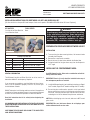
DRIFTWOOD AND RIVER ROCK KITS
P/N 901011-00
Rev. A, 01/2020
HEARTH PRODUCTS
KITS AND ACCESSORIES
KIT CONTENTS
1 ea. Log Set or River Rock Set
1 ea. Instruction Sheet
INSTALLATION INSTRUCTIONS FOR DRIFTWOOD LOG SETS AND RIVER ROCK SET
[For Use with Astria® CompassDLX and Compass Series and Superior® DRL2000 & DRL3500 Series DV Linear Fireplaces]
GENERAL INFORMATION
The Driftwood Log Set and River Rock Set are to be used as a
decorative addition in contemporary fireplaces.
If you encounter any problems, need clarification of these instruc-
tions or are not qualified to properly install this kit, contact your
local distributor or dealer.
DO NOT attempt to install the logs and river rock until the appliance
installation has been completed, the gas line connected and tested
for leaks and the initial burner operation has been checked out.
Read this instruction sheet in its entirety before beginning the
installation.
ALL WARNINGS AND PRECAUTIONS IN THE INSTALLATION AND
OPERATION MANUAL PROVIDED WITH THE APPLIANCE APPLY TO
THESE INSTRUCTIONS.
SHUT DOWN THE APPLIANCE AND ALLOW IT TO COMPLETELY
COOL BEFORE PROCEEDING.
TOOLS NEEDED
None
PREPARING THE FIREPLACE FOR DRIFTWOOD LOG SET
INSTALLATION
1. To access the glass door securing latches, first remove facade
assembly from fireplace.
2. Remove the screen barrier assembly.
3. Detach the two (2) door latches beneath the firebox floor.
4. Swing the bottom of the glass door away from the fireplace to
a 45° angle.
INSTALLING THE CONTEMPORARY MEDIA
Install Driftwood Log Set, River rock or combination of both fol-
lowing instructions below.
IMPORTANT: Panels (if used) should be installed before any of
the contemporary media are installed.
1. Install the Driftwood Log Set (see installation instructions on Page 2
for 35” models, Page 3 for 45” models and Page 4 for 55” models).
2. Ensure that glass media remains spread in a thin layer behind
burner and two layers (max) in front of burner and one layer over
the burner. Leave the pilot area open and take care to not allow
crushed glass to fall into between the pilot cover and burner.
NOTE: When installing log set or river rock, take care to NOT mound
glass media.
IMPORTANT: Be sure that burner flames do not impinge upon
neither driftwood media or river rocks.
River Rock Set
Driftwood Log Set
WARNING
If contemporary media are not installed according
to the installation instructions, flame impingement
and improper combustion could occur and result
in soot and/or excessive production of carbon
monoxide (CO), a colorless, odorless, toxic gas.
45” Model Shown

2NOTE: DIAGRAMS & ILLUSTRATIONS ARE NOT TO SCALE.
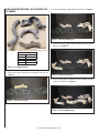
1. Place rear left log (1) behind burner up against rear wall (see
Figure 2).
2. Place rear right log (2) against right and rear walls (see Figure 3).
Figure 2 - Place Rear Left Log (1)
Figure 1 - 35” Driftwood Log Set
Figure 3 - Place Rear Right Log (2)
35” Driftwood Log Set
Item # Description
1 Rear Left Log
2 Rear Right Log
3 Left Front Log
4 Front Right Log
35” Model Shown
INSTALLATION INSTRUCTIONS, LOG PLACEMENT ONLY
35” MODELS
3. Place left front log (3) against left wall and laying on front angeled
portion. (see Figure 4).
4. Place front right log (4) in-between left front and right rear logs
in front of the burner (see Figure 5).
Figure 5 - Place Front Right Log (4)
Figure 4 - Place Left Front Log (3)
4
4
2
2
1
1
3
3

3
NOTE: DIAGRAMS & ILLUSTRATIONS ARE NOT TO SCALE.
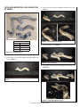
1. Place rear log (1) in center of fireplace leaning up against rear
wall (see Figure 7).
2. Place left hand side log (2) wrapping around the burner (see
Figure 8).
Figure 7
Figure 6 - 45” Driftwood Log Set
Figure 8 - Place Left Hand Side Log (2)
45” Driftwood Log Set
Item # Description
1 Rear Log
2 Left Log
3 Front Log
4 Right Log
45” Model Shown
INSTALLATION INSTRUCTIONS, LOG PLACEMENT ONLY
45” MODELS
3. Place Front log (3) (see Figure 9).
4. Place right hand side log (4) wrapping around the burner (see
Figure 10).
Figure 9 - Place Front Log (3)
Figure 10 - Place Right Hand Side Log (4)
4
4
2
2
1
1
3
3
4
2
2

4NOTE: DIAGRAMS & ILLUSTRATIONS ARE NOT TO SCALE.
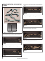
1. Place Right side log (# 5) parallel with side around burner.
2. Place Right rear log (# 2) behind burner and against rear wall.
3. Place Left rear log (# 1) behind burner and leaning against rear
wall.
4. Place Left side log (# 6) around burner, against left wall and rear
walls.
5. Place Front left log (# 4) in front of burner.
6. Place Front right log (# 3) in front of burner.
INSTALLATION INSTRUCTIONS, LOG PLACEMENT ONLY
55” MODELS
Figure 12
Figure 13
Figure 15
Figure 16
Figure 17
Figure 14
Figure 11 - 55” Driftwood Log Set
55” Driftwood Log Set
Item # Description
1 Left rear log
2 Right rear log
3 Front right log
4 Front left log
5 Right side log
6 Left side log
4
4
2
2
1
1
3
3
5
5
6
6
55” Model Shown

5
NOTE: DIAGRAMS & ILLUSTRATIONS ARE NOT TO SCALE.
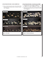
INSTALLATION INSTRUCTIONS - ROCK PLACEMENT ONLY
1. Rocks can be placed anywhere on glass media provided no flame
impingement occurs from burner flames (see typical installation
shown in Figure 18).
INSTALLATION INSTRUCTIONS - ROCK AND LOG PLACEMENT
1. Follow log placement instructions guide (see Page 2 for 35” mod-
els, Page 3 for 45” models and Page 4 for 55” models).
2. Place rocks around and/or on logs as desired provided no flame
impingement occurs from burner flames (see typical installation
shown in Figure 19).
Figure 18 - Place Rocks Figure 19 - Rock and Log Placement
45” Model Shown
55” Model Shown
35” Model Shown
45” Model Shown
55” Model Shown
35” Model Shown

6NOTE: DIAGRAMS & ILLUSTRATIONS ARE NOT TO SCALE.
WARNING
Reinstall any barrier removed before operating the
fireplace. The barrier is designed to reduce the risk
of burns from hot glass. Do not operate the fireplace
without the barrier installed.
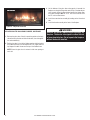
RE-INSTALLING THE GLASS DOOR, BARRIER, AND FACADE
1. Retrieve the glass door. Visually inspect the gasket on the back-
side of the frame. Gasket surface must be clean, free of irregulari-
ties and seated firmly.
2. Position the door in front of the firebox opening with the bottom
of the door held away from the fireplace at a 45° angle. Hook the
top flange of the door frame over the top of the firebox frame.
NOTE: Ensure the glass door is centered—with even spacing on
each side.
45” Model Shown
Figure 20 - Completed Installation
3. Let the bottom of the glass door swing gently in towards the
fireplace ensuring that the gasket seats evenly as the door draws
shut. Securely fasten the door latches beneath the firebox floor
to the door V-flange. Note: 35” & 45” units have 2 latches while
the 55” unit has three latches.
4. Install the screen barrier assembly by hooking on the 4 bend out
tabs.
5. Install the facade assembly to the front of the fireplace.

7
NOTE: DIAGRAMS & ILLUSTRATIONS ARE NOT TO SCALE.
______________________________________________________
______________________________________________________
______________________________________________________
______________________________________________________
______________________________________________________
______________________________________________________
______________________________________________________
______________________________________________________
______________________________________________________
______________________________________________________
______________________________________________________
______________________________________________________
______________________________________________________
______________________________________________________
______________________________________________________
______________________________________________________
______________________________________________________
______________________________________________________
______________________________________________________
______________________________________________________
______________________________________________________
______________________________________________________
______________________________________________________
______________________________________________________
______________________________________________________
______________________________________________________
______________________________________________________
______________________________________________________
______________________________________________________
______________________________________________________
______________________________________________________
______________________________________________________
______________________________________________________
______________________________________________________
______________________________________________________
______________________________________________________
______________________________________________________
NOTES

8
NOTE: DIAGRAMS & ILLUSTRATIONS ARE NOT TO SCALE.
Printed in U.S.A. © 2019 Innovative Hearth Products
P/N 901011-00 Rev. A 01/2020
Innovative Hearth Products (IHP) reserves the right to make changes at any time, without notice, in design, materials, specifications, prices and also to discontinue colors, styles and products.
Consult your local distributor for fireplace code information.
IHP
1769 East Lawrence Street • Russellville, AL 35654
-
 1
1
-
 2
2
-
 3
3
-
 4
4
-
 5
5
-
 6
6
-
 7
7
-
 8
8


Astria Fireplaces COMPASS Instruction Sheet
- Type
- Instruction Sheet
- This manual is also suitable for
Ask a question and I''ll find the answer in the document
Finding information in a document is now easier with AI
Related papers
-
Astria Fireplaces Merit Contemporary Instruction Sheet
-
-
-
-
-
-
-
Other documents
-
Superior Fireplaces VRL3000 Operating instructions
-
-
-
-
-
Kingsman Fireplaces IDV34/44 User manual
-
-
-
-