Page is loading ...

READ &SAVE THESE INSTRUCTIONS
3500-Lb. Capacity Electric Trailer Jack
Owner’s Manual
WARNING: Read carefully and understand all ASSEMBLY AND OPERATION
INSTRUCTIONS before operating. Failure to follow the safety rules and other basic safety
precautions may result in serious personal injury.
Item #57404

Page 2 of 15
Thank you very much for choosing an Ultra-Tow™ product!
For future reference, please complete the owner’s record below:
Serial Number/Lot Date Code: ________________________________
Purchase Date: ____________________________________________
Save the receipt, warranty, and this manual. It is important that you read
the entire manual to become familiar with this product before you begin
using it.
This trailer jack is designed for certain applications only. Northern Tool
and Equipment is not responsible for issues arising from modification or
improper use of this product such as an application for which it was not
designed. We strongly recommend that this product not be modified
and/or used for any application other than that for which it was designed.
For technical questions, please call 1-800-222-5381.

Page 3 of 15
Table of Contents
Intended Use .......................................................................................................................................... 4
Packaging Contents .............................................................................................................................. 4
Technical Specifications ...................................................................................................................... 4
Important Safety Information ............................................................................................................... 4
Specific Operation Warnings ............................................................................................................... 6
Main Parts of Trailer Jack..................................................................................................................... 7
Assembly Instructions .......................................................................................................................... 7
Before Each Use .................................................................................................................................... 8
Operating Instructions .......................................................................................................................... 8
After Each Use ....................................................................................................................................... 9
Maintenance .......................................................................................................................................... 9
Troubleshooting .................................................................................................................................. 10
Parts Diagram ...................................................................................................................................... 12
Parts List .............................................................................................................................................. 13
Replacement Parts .............................................................................................................................. 13
Limited Warranty ................................................................................................................................. 14

Page 4 of 15
Intended Use
The Ultra-Tow 3500-Lb. Capacity Electric Trailer Jack is a fast, easy, and practical way to hitch and
level trailers with A-frame couplers. The 7-way connector plugs into your vehicle to let you lift or lower
the jack with the push of a button, no hard wiring required. It has a water-proof, one-piece, industrial
design cover. Improved LEDs illuminate the area to the front of the jack for superior nighttime visibility.
The plastic connector storage bracket holds your 7-Way connector firmly in place to protect from
weather, dirt, and damage.
Packaging Contents
Technical Specifications
Property
Specification
Type
12V DC A-Frame
Lift Capacity (lb.)
3,500
Support Capacity (lb.)
5,250
Clearance: Bracket to Jack Top (in.)
22
Length of Travel (in.)
18
Length Retracted (in.)
9 (Measured from ground to center of mounting point)
Length Extended (in.)
31-1/2 (Measured from ground to center of mounting point)
Drop Leg Travel (in.)
4-1/2
Jack Tube Size (in.)
2-1/4
Crank Type
Includes manual crank handle
Ground Support
Foot pad
Mount Type
A-frame mounting plate
Construction
Steel
Mount Type
Fits 2 ¼ inch mounting holes
Mount Height (in.)
9
Important Safety Information
⚠WARNING
• Read and understand all instructions. Failure to follow all instructions may result in serious injury
or property damage.
• The warnings, cautions, and instructions in this manual cannot cover all possible conditions or
Tools and Components Required
• A-Frame Coupler with Lower Support Plate (owner supplied, not included)
• Three Grade 5, 1inch Long, 3/8 inch-16 UNC Bolts
• Three 3/8 inch Flat Washers
• Three Lock Washers
• 9/16 inch Wrench (owner supplied, not included)
• Torque Wrench (owner supplied, not included)
• Wire Cutters (owner supplied, not included)
• Wire Strippers (owner supplied, not included)
• Crimpers or Soldering Iron (owner supplied, not included)

Page 5 of 15
situations that could occur. Exercise common sense and caution when using this tool. Always be
aware of the environment and ensure that the tool is used in a safe and responsible manner.
• Do not allow persons to operate or assemble the jack until they have read this manual and have
developed a thorough understanding of how it works.
• Do not modify this jack in any way. Unauthorized modification may impair the function and/or
safety and could affect the life of the product. There are specific applications for which the jack
was designed.
• Use the right tool for the job. DO NOT attempt to force small equipment to do the work of larger
industrial equipment. There are certain applications for which this equipment was designed. This
jack will be safer and do a better job at the capacity for which it was intended. DO NOT use this
equipment for a purpose for which it was not intended.
• Industrial or commercial applications must follow OSHA requirements.
⚠WARNING
WORK AREA SAFETY
• Inspect the work area before each use. Keep work area clean, dry, free of clutter, and well-lit.
Cluttered, wet, or dark work areas can result in injury. Using the jack in confined work areas may
put you dangerously close to cutting tools and rotating parts.
• Do not use the jack where there is a risk of causing a fire or an explosion; e.g., in the presence of
flammable liquids, gases, or dust. The jack can create sparks, which may ignite the flammable
liquids, gases, or dust.
• Do not allow the jack to come into contact with an electrical source. The tool is not insulated and
contact will cause electrical shock.
• Keep children and bystanders away from the work area while operating the tool. Do not allow
children to handle the jack.
⚠WARNING
PERSONAL SAFETY
• Stay alert, watch what you are doing, and use common sense when operating the tool. Do not use
the tool while you are tired or under the influence of drugs, alcohol, or medication. A moment of
inattention while operating the tool may result in serious personal injury.
• Dress properly. Do not wear loose clothing, dangling objects, or jewelry. Keep your hair, clothing
and gloves away from moving parts. Loose clothes, jewelry, or long hair can be caught in moving
parts. Air vents on the tool often cover moving parts and should be avoided.
• Wear the proper personal protective equipment when necessary. Use ANSI Z87.1 compliant safety
goggles (not safety glasses) with side shields, or when needed, a face shield. Use a dust mask in
dusty work conditions. Also use non-skid safety shoes, hardhat, gloves, dust collection systems,
and hearing protection when appropriate. This applies to all persons in the work area.
• Do not overreach. Keep proper footing and balance at all times.
• Remove keys or wrenches before connecting the tool to an air supply, power supply, or turning on

Page 6 of 15
the tool. A wrench or key that is left attached to a rotating part of the tool may cause personal
injury.
⚠CAUTION
TRAILER JACK USE AND CARE
• Do not force the trailer jack. Products are safer and do a better job when used in the manner for
which they are designed. Plan your work, and use the correct product for the job.
• Check for damaged parts before each use. Carefully check that the trailer jack will operate
properly and perform its intended function. Replace damaged or worn parts immediately. Never
operate the trailer jack with a damaged part.
• Do not use a trailer jack with a malfunctioning switch. Any power tool that cannot be controlled
with the power switch is dangerous and must be repaired by an authorized service representative
before using.
• Disconnect the power/air supply from the trailer jack and place the switch in the locked or off
position before making any adjustments, changing accessories, or storing the tool. Such
preventive safety measures reduce the risk of starting the tool accidentally.
• Store the trailer jack when it is not in use. Store it in a dry, secure place out of the reach of
children. Inspect the tool for good working condition prior to storage and before re-use.
• Use only accessories that are recommended by the manufacturer for use with your product.
Accessories that may be suitable for one product may create a risk of injury when used with
another tool. Never use an accessory that has a lower operating speed or operating pressure than
the tool itself.
Specific Operation Warnings
⚠WARNING
• To prevent injury or property damage, read and understand owner's manual before operating.
• Do not exceed the rated load capacity.
• The trailer jack is designed for vertical loading. Excessive side forces may cause jack failure.
• Do not use crank while power lift is in use.
• Wear ANSI Z87.1 compliant safety goggles during use.
• For use on flat, level, hard surface capable of supporting load.
• Prevent trailer wheels from moving using wheel chocks while raising or lowering.
• Before towing, fully raise trailer jack and secure properly.
• Keep body parts clear from under jack and tongue when applying and releasing load, or moving
trailer.
• Do not use blocks for additional ground clearance.
• To avoid accidental shock and/or damage to the electrical system, disconnect the battery ground

Page 7 of 15
cable before installation.
• When using the drop foot or drop leg, make certain the supplied pin is fully inserted through both
sides of the inner tube and the drop tube before using the jack.
• If the trailer jack has a drop leg, never attempt to adjust the drop leg when there is any load on the
jack.
Main Parts of Trailer Jack
Reference
Subassembly
1
Hand Crank Handle
2
Light Switch
3
Extend / Retract Motor Switch
4
Connector Storage Bracket
5
(3) Graded 5, 1 in. long, 3/8in.-16 UNC Bolts
6
(3) 3/8in. Flat Washers
7
(3) Lock Washers
8
7-way connector
9
Drop Leg
Assembly Instructions
⚠WARNING
• Keep hands, feet, and body clear of the jack and trailer to avoid the risk of injury or death!
• Compare the lift capacity of the jack with your trailer to ensure safe operation of the jack.

Page 8 of 15
Before Each Use
⚠WARNING
• Before each use, inspect jack tubes and replace if bent or damaged.
• Compare the lift capacity of the jack with your trailer to ensure safe operation of the jack.
• Park the trailer on a level surface, block the tires of the trailer, and support trailer tongue.
• This jack has been designed to attach to the top surface of the A-frame coupler.
• Detach the drop leg of the jack by removing the lock pin and sliding it out.
• Position the drop leg in line with the mounting hole with the foot of the drop leg on the ground.
• Place the jack’s outer tube through the A-frame coupler hole and over the drop leg. The dual
mounting pattern allows positioning of the jack either facing the two vehicles or for curb-side
operation.
• Secure the jack using three (3) 3/8” diameter, 1” long, grade 5 bolts, and lock washers. Bolts
should be tightened to 15-20 ft. lb.
• Route the black wire lead from the plastic cover along the trailer to the battery. Attach the wire
lead to the trailer using cable ties or equivalent.
• Connect the wire lead from the jack directly to the positive (+) terminal of the battery. This unit has
a built-in circuit breaker which automatically trips and resets. Reconnect the battery ground cable.
• Connect the 7-pin connector to the towing vehicle, no hard wiring required.
• Check for proper installation. Press the motor switch UP for extending the jack and DOWN for
retracting the jack. Also check that the light switch turns on the LED light situated under the top
cover of the jack.
• After checking for proper operation, be sure to reattach the drop leg to the inner tube of the jack
using the lock pin.
• Retract the jack completely.
Operating Instructions
⚠WARNING
• Do not exceed the rated load capacity.
• The trailer jack is designed for vertical loading. Excessive side forces may cause jack failure.
• Do not use crank while power lift is in use.
• For use on flat, level, hard surface capable of supporting load.
• Prevent trailer wheels from moving using wheel chocks while raising or lowering.
• Keep body parts clear from under jack and tongue when applying and releasing load, or moving
trailer.

Page 9 of 15
• Release the Power Switch when the motor slows, or switches off, to prevent damage to the motor.
Wait 15 seconds for the motor to reset before operating the jack again.
• Do not stack blocks under the jack’s foot to increase the height. Stacked blocks may become
unstable and fall.
• When using the drop foot or drop leg, make certain the supplied pin is fully inserted through both
sides of the inner tube and the drop tube before using the jack.
• If the trailer jack has a drop leg, never attempt to adjust the drop leg when there is any load on the
jack.
• Park your trailer on a level surface and block all trailer wheels.
• For nighttime hook-ups, flip the light switch ON to illuminate the work area.
• Before operating the jack, attach the foot with the 3/8” safety lock pin provided.
• Extend the jack by pushing the operating switch UP. The drop leg may also be used to quickly
extend the jack. Make sure to reattach the lock pin after adjusting the drop leg to the desired
level. Under heavy use, the internal circuit breaker may open, causing the motor to switch off. In
this case, release the operating switch and wait 15 seconds for the breaker to reset before
resuming operation.
• Retract the jack by pushing the operating switch DOWN. The jack will stop automatically at the
end of the extension or retraction stroke. If you attempt to extend or retract the jack and it does
not respond, it may be at the end of the stroke. If the jack fails to respond, try operating it in the
opposite direction. If it will not operate in either direction then see the troubleshooting section.
After full retracting, you may need to raise the drop leg. Make sure to reattach the lynch pin after
adjusting the drop leg to the desired level.
• If, for any reason, electric power is lost or you need to disconnect the jack from the power source,
remove the rubber lid on top of the plastic cover. Insert the manual crank handle into the access
hole on the top of the jack, engaging the drive screw. While holding the crank firmly in place,
rotate it counter-clockwise to extend the jack, and clockwise to retract it.
• Over or under extending the jack by holding the switch too long WILL NOT cause damage on the
gears of the Ultra-Tow Electric Trailer Jack.
• Automatic thermal protection equipped on this jack can prevent damage from motor overheating.
After Each Use
⚠WARNING
• After use, wipe external surfaces of the jack with a clean cloth.
• Keep all moving parts lightly lubricated to prevent corrosion.
Maintenance
⚠WARNING
• Before each use, inspect jack tubes and replace if bent or damaged.

Page 10 of 15
• If wiring is connected to battery terminal, inspect at least twice each year for corrosion. Clean with
a solution of baking soda and water, and then apply a thin coat of grease.
• The motor’s ground screw and mounting bolts must be cleaned if a grounding continuity problem
occurs.
Maintain the product by adopting a program of conscientious repair and maintenance in accordance
with the following recommended procedures. It is recommended that the general condition of any tool
be examined before it is used. Keep your tool in good repair. Keep handles dry, clean, and free from
oil and grease. Also refer to the engine manufacturer’s instruction manual for additional information
about engine maintenance. The following chart is based on a normal operation schedule.
Maintenance Interval
Maintenance Point
Daily before operating
The powered A-frame jack motor is sealed and maintenance-
free.
Before each use, inspect jack tubes and replace if bent or
damaged.
Ensure all connections are tight and free of corrosion and that
the jack is properly ground with the coupler (metal to metal
contact).
If necessary, wash with mild soap and water and rinse
thoroughly. The motor ground screw and mounting bolts must
be cleaned too if a ground continuity problem occurs.
After the first 20 operating hours
Fully extend the jack and clean the inner jack tube.
After the first 50 operating hours or
every week
Fully extend the jack and clean the inner jack tube.
Every year
Fully extend the jack and clean the inner jack tube once per
year. After cleaning, coat the tube with a light grease or
silicone spray lubricant.
Troubleshooting
Failure
Possible Cause
Corrective Action
Motor will not
operate.
No or low voltage.
Check battery and electrical
connections. Must have minimum of 10
VDC. If the battery is low, plug the
trailer cable into the tow vehicle, and
start the tow vehicle to provide power
to the jack.
Poor grounding.
Clean area between the jack mounting
plate and coupler, and ensure paint

Page 11 of 15
Failure
Possible Cause
Corrective Action
has been removed by the star
washers. Direct metal-to-metal contact
must exist between mounting
components to ensure good electrical
contact.
Internal circuit breaker has opened.
Wait 15 seconds for breaker to close.
Manual reset circuit breaker has
opened.
Reset the breaker by pressing the
button on the breaker.
Loose wires on ON/OFF switch.
Secure wire connections.
ON/OFF switch is faulty.
Replace switch.
Faulty motor.
Replace motor.
Light doesn’t
work.
Loose wires on the ON/OFF switch.
Secure wire connection.
Bad light bulb.
Replace bulb.

Page 12 of 15
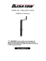
Parts Diagram

Page 13 of 15
Parts List
Part Number
Part Description
Quantity
1
Override Protection Cover
1
2
Plastic Cover
1
3
LED Light Switch
1
4
Up/Down Switch
1
5
Motor
1
6-10
Gear Assembly
1
11
Drive Shaft
1
12
Short Positive/Negative Wire
1
13
LED Light
1
14
Wiring Board
1
15
ACME Screw
1
16
Outer Tube
1
17
Crank
1
18
Mounting Plate
1
19
Cord Caddy
1
20
Inner Tube
1
21
7-Way Connector
1
22
Lock Pin
1
23
Drop Leg
1
24
Up/Down Switch Cover
1
25
LED Wire
1
26
Hardware Kit
3
27
LED Switch Cover
1
Replacement Parts
• For replacement parts and technical questions, please call Customer Service at 1-800-222-5381.
• Not all product components are available for replacement. The illustrations provided are a
convenient reference to the location and position of parts in the assembly sequence.
• When ordering parts, the following information will be required: item description, item model
number, item serial number/item lot date code, and the replacement part reference number.
• The distributor reserves the rights to make design changes and improvements to product lines
and manuals without notice.

Page 14 of 15
Limited Warranty
Northern Tool and Equipment Company, Inc. ("We'' or "Us'') warrants to the original purchaser only
("You'' or "Your") that the Ultra-Tow product purchased will be free from material defects in both
materials and workmanship, normal wear and tear excepted, for a period of one year from date of
purchase. The foregoing warranty is valid only if the installation and use of the product is strictly in
accordance with product instructions. There are no other warranties, express or implied, including the
warranty of merchantability or fitness for a particular purpose. If the product does not comply with this
limited warranty, Your sole and exclusive remedy is that We will, at our sole option and within a
commercially reasonable time, either replace the product or product component without charge to You
or refund the purchase price (less shipping). This limited warranty is not transferable.
Limitations on the Warranty
This limited warranty does not cover: (a) normal wear and tear; (b) damage through abuse, neglect,
misuse, or as a result of any accident or in any other manner; (c) damage from misapplication,
overloading, or improper installation; (d) improper maintenance and repair; and (e) product alteration
in any manner by anyone other than Us, with the sole exception of alterations made pursuant to
product instructions and in a workmanlike manner.
Obligations of Purchaser
You must retain Your product purchase receipt to verify date of purchase and that You are the original
purchaser. To make a warranty claim, contact Us at 1-800-222-5381, identify the product by make
and model number, and follow the claim instructions that will be provided. The product and the
purchase receipt must be provided to Us in order to process Your warranty claim. Any returned
product that is replaced or refunded by Us becomes our property. You will be responsible for return
shipping costs or costs related to Your return visit to a retail store.
Remedy Limits
Product replacement or a refund of the purchase price is Your sole remedy under this limited warranty
or any other warranty related to the product. We shall not be liable for: service or labor charges or
damage to Your property incurred in removing or replacing the product; any damages, including,
without limitation, damages to tangible personal property or personal injury, related to Your improper
use, installation, or maintenance of the product or product component; or any indirect, incidental or
consequential damages of any kind for any reason.
Assumption of Risk
You acknowledge and agree that any use of the product for any purpose other than the specified
use(s) stated in the product instructions is at Your own risk.
Governing Law
This limited warranty gives You specific legal rights, and You also may have other rights which vary
from state to state. Some states do not allow limitations or exclusions on implied warranties or
incidental or consequential damages, so the above limitations may not apply to You. This limited
warranty is governed by the laws of the State of Minnesota, without regard to rules pertaining to
conflicts of law. The state courts located in Dakota County, Minnesota shall have exclusive jurisdiction
for any disputes relating to this warranty.

Page 15 of 15
Distributed by:
Northern Tool & Equipment Company, Inc.
Burnsville, Minnesota 55306
www.northerntool.com
Made in China
/