


VS-44FO – Contents
i
Contents
1 Introduction 1
2 Getting Started 2
2.1 Achieving the Best Performance 2
2.2 Safety Instructions 2
2.3 Recycling Kramer Products 3
3 Overview 4
3.1 Defining the SFP 5
3.2 Defining the VS-44FO 4x4 3G HD-SDI Fiber Optic Matrix Switcher 5
4 Installing in a Rack 8
5 Connecting the VS-44FO 9
5.1 Installing the SFP Modules 11
5.2 Connecting the RS-232 Port 12
5.3 Connecting a PC or Controller to the RS-485 Port 14
5.4 Switching Genlocked Video Signals 15
5.5 Connecting the Ethernet Port 16
5.6 Configuring the Ethernet Port Initially 18
5.7 Controlling Using the Ethernet Port 20
5.8 Using the Ethernet Reset Button 20
6 Operating the VS-44FO 21
6.1 Operating the VS-44FO from the Front Panel 21
6.2 Using Serial Commands 24
6.3 Using the Infrared Remote Controller 24
6.4 Upgrading the Firmware 25
6.5 Changing the Device Parameters 25
7 Technical Specifications 26
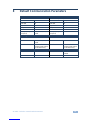
8 Default Communication Parameters 27
9 Kramer Protocol 3000 28
9.1 Switching Protocols 28
9.2 Kramer Protocol 3000 Syntax 29
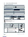
9.3 Kramer Protocol 3000 Commands 32
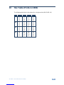
10 Hex Table (Protocol 2000) 35
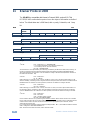
11 Kramer Protocol 2000 36
Figures
Figure 1: VS-44FO 4x4 3G HD-SDI Fiber Optic Matrix Switcher Front Panel 6
Figure 2: VS-44FO 4x4 3G HD-SDI Fiber Optic Matrix Switcher Rear Panel 7
Figure 3: Connecting the VS-44FO 11
Figure 4: Installing the SFP Modules 12
Figure 5: DIP-Switch Settings 14
Figure 6: Local Area Connection Properties Window 17
Figure 7: Internet Protocol (TCP/IP) Properties Window 17
Figure 8: K-UPLOAD Main Screen 18
Figure 9: Connect Screen 19
Figure 10: Device Properties Screen 19

VS-44FO - Introduction
1
1 Introduction
Welcome to Kramer Electronics! Since 1981, Kramer Electronics has been
providing a world of unique, creative, and affordable solutions to the vast range of
problems that confront the video, audio, presentation, and broadcasting
professional on a daily basis. In recent years, we have redesigned and upgraded
most of our line, making the best even better!
Our 1,000-plus different models now appear in 11 groups that are clearly defined
by function: GROUP 1: Distribution Amplifiers; GROUP 2: Switchers and Routers;
GROUP 3: Control Systems; GROUP 4: Format/Standards Converters; GROUP 5:
Range Extenders and Repeaters; GROUP 6: Specialty AV Products; GROUP 7:
Scan Converters and Scalers; GROUP 8: Cables and Connectors; GROUP 9:
Room Connectivity; GROUP 10: Accessories and Rack Adapters and GROUP 11:
Sierra Products.
Congratulations on purchasing your Kramer VS-44FO 4x4 3G HD-SDI Fiber Optic
Matrix Switcher, which is ideal for the following typical applications:
Professional broadcasting and production studios
Presentation applications

2
VS-44FO – Getting Started
2 Getting Started
We recommend that you:
Unpack the equipment carefully and save the original box and packaging
materials for possible future shipment
Review the contents of this user manual
Use Kramer high-performance high-resolution cables
Go to http://www.kramerelectronics.com/support/product_downloads.asp
to check for up-to-date user manuals, application programs, and to check
if firmware upgrades are available (where appropriate).
2.1 Achieving the Best Performance
To achieve the best performance:
Use only good quality connection cables to avoid interference, deterioration
in signal quality due to poor matching, and elevated noise levels (often
associated with low quality cables)
Do not secure the cables in tight bundles or roll the slack into tight coils
Avoid interference from neighboring electrical appliances that may adversely
influence signal quality
Position your Kramer VS-44FO away from moisture, excessive sunlight and dust
This equipment is to be used only inside a building. It may only be
connected to other equipment that is installed inside a building.
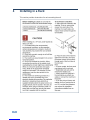
2.2 Safety Instructions
Caution:
There are no operator serviceable parts inside the unit
Warning:
Use only the power cord that is supplied with the unit
Warning:
Do not open the unit. High voltages can cause
electrical shock! Servicing by qualified personnel only
Warning:
Disconnect the power and unplug the unit from the wall
before installing
i
!
!

VS-44FO - Getting Started
3
2.3 Recycling Kramer Products
The Waste Electrical and Electronic Equipment (WEEE) Directive 2002/96/EC
aims to reduce the amount of WEEE sent for disposal to landfill or incineration by
requiring it to be collected and recycled. To comply with the WEEE Directive,
Kramer Electronics has made arrangements with the European Advanced
Recycling Network (EARN) and will cover any costs of treatment, recycling and
recovery of waste Kramer Electronics branded equipment on arrival at the EARN
facility. For details of Kramer’s recycling arrangements in your particular country
go to our recycling pages at http://www.kramerelectronics.com/support/recycling/.

4
VS-44FO – Overview
3 Overview
The VS-44FO is a high-performance matrix switcher for fiber optic signals. It can
switch any or all inputs to any or all outputs simultaneously.
In particular, the VS-44FO features:
A maximum data rate of up to 3Gbps, enabling it to be used for standard
definition, high-definition and the new 3G high definition serial digital video
signals (3G HD-SDI)
A range of up to 40km (depending on the SFP module used)
HDTV compatibility
A single mode SFP (small form-factor pluggable) SDI fiber optic connector
for the input and the output
A looping analog sync for genlock – bi-level and tri-level sync compatible
Selectable sync signal termination
Automatic reclocking and equalization
Active input reporting where each input LED on the front panel automatically
lights when the unit detects a video signal on that input
Multiple memory locations that store multiple switches as presets (salvos) to
be recalled and executed when needed
A Take button that executes multiple switches all at once
Vertical interval switching that synchronizes either to an external reference
or to the incoming video in compliance with SMPTE RP-168
Flexible control options including front panel, RS-232 (K-router™
Windows®-based software is included), RS-485, Ethernet and IR
Laser Class I acc. 21 CFR 1040 and Class 1 per IEC 60825-1 compliance
The VS-44FO is housed in a 19" 1U rack-mountable enclosure, and is fed from a
100-240V AC universal switching power supply.

VS-44FO - Overview
5
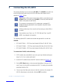
The unit can be controlled using the front panel buttons or:
Using an RC-IR3 infrared remote control transmitter (included)
Remotely, by RS-232 or RS-485 serial commands transmitted by a PC,
touch screen system, or other serial controller
Via the Ethernet
By default, the VS-44FO is controlled using the Kramer 3000 protocol (see Section
6.1.9 for details of how to switch to Protocol 2000 and Section 9 for the relevant
protocol commands).
3.1 Defining the SFP
An SFP is a small form-factor pluggable transceiver that is a compact, hot-
swappable, input/output transceiver used in data communication and
telecommunications networks. The SFP interfaces between communication
devices like switches, routers and fiber optic cables, and performs conversions
between optical and electrical signals.
The SFP transceiver is specified by the SFP Transceiver Multisource Agreement
(MSA), which was developed and is followed by different transceiver
manufacturers. SFP transceivers have a wide range of detachable interfaces to
multimode/single-mode fiber optics that allows users to select the appropriate
transceiver according to the required optical range for the network. The VS-44FO
supports use of non-MSA (SFP Transceiver Multisource Agreement) video
modules and MSA communication modules.
The optical transceiver modules are engineered for exceptional performance in the
presence of SDI pathological patterns. The transceivers feature best-in-class
optical receiver sensitivity for SMPTE 259M, SMPTE 344M, SMPTE 292M and
SMPTE 424M serial rates, to provide superior optical link budget and robustness.
3.2 Defining the VS-44FO 4x4 3G HD-SDI Fiber Optic Matrix
Switcher
This section defines the VS-44FO.

VS-44FO – Overview
6
Figure 1: VS-44FO 4x4 3G HD-SDI Fiber Optic Matrix Switcher Front Panel
#
Feature
Function
1
IR Receiver
The yellow LED illuminates when receiving signals from the infrared remote control transmitter
2
POWER LED
Illuminates when the unit is ON
3
ALL Button
Pressing ALL followed by an INPUT button, connects that input to all outputs
4
OFF Button
Pressing OFF+OUT disconnects that output from the inputs;
pressing OFF+ALL disconnects all the outputs
5
IN SELECT Buttons
Select the input to switch to the output;
long presses on buttons IN 1 to IN 4 change the genlock timing (see Section 5.4)
Pressing IN 1 + IN 2 together gives NTSC timing
6
OUT SELECT Buttons
Select the output to which the input is switched; pressing OUT 1+OUT 2 selects Protocol 2000; pressing
OUT 1+OUT 3 selects Protocol 3000
7
STO (STORE) Button
Pressing STO followed by an IN/OUT button stores the current setting
8
RCL (RECALL) Button
Pressing the RCL button and the corresponding IN/OUT key under the selected button recalls a setup
from the non-volatile memory
9
LOCK Button
A long press toggles activation/inactivation of the front panel buttons
10
TAKE Button
Pressing TAKE toggles the mode between the CONFIRM mode and the AT ONCE mode (user
confirmation per action is unnecessary)
11
INPUT STATUS LEDs
Illuminate green when an active input is detected
12
7-segment Display
Displays the selected input switched to the output (marked above each input)

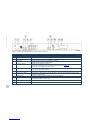
Figure 2: VS-44FO 4x4 3G HD-SDI Fiber Optic Matrix Switcher Rear Panel
#
Feature
Function
13
GENLOCK BNC Connector
Connects to the genlock source
14
TERM HI-Z/75Ω Pushbutton
Press to terminate the genlock source (75Ω) or release for looping
15
LOOP BNC Connector
Connects to a display or the next chained Genlock connector
16
SFP/SFP+ Out/In Receptacles
Holds an SFP module in each OUT/IN receptacle (1 – 4). Each SFP connects a double
fiber cable to an input and output
17
PROG/UPDATE USB connector
Connects to a computer to upgrade machine firmware
18
RS-232 9-pin D-sub (F) Port
Connects to the PC or the remote controller
19
MACH # and PROG/RS-485 TERM
DIP-switches
MACH # DIP-switches 1-4 set the Machine Number of the unit,
PROG DIP-switch enables a microcontroller firmware upgrade,
RS-485 TERM DIP-switch terminates the RS-485 line with a 120Ω load
20
RS-485 Terminal Block Port
Pins B (-) and A (+) are for RS-485;
Pin G may be connected to the shield (if required)
21
Ethernet RJ-45 Connector
Connects to the PC or other serial controller through computer networking LAN
22
SFP SELECT Button
Press for non-MSA (SFP Transceiver Multisource Agreement) video module; release for
MSA communication module
23
FACTORY RESET Button
Press to reset to factory default definitions:
IP number 192.168.1.39, Mask – 255.255.0.0, Gateway – 0.0.0.0
First disconnect the power cord and then connect it again while pressing the Factory Reset
button. The unit powers up and loads its memory with the factory default definitions and erases
all stored preset
24
Power Connector, Power Switch and
Fuse
AC connector enabling power supply to the unit; switch that turns the power to the unit
ON (1) and OFF (0)
7
VS-44FO – Overview


VS-44FO - Connecting the VS-44FO
9
5 Connecting the VS-44FO
This section describes how to connect the VS-44FO. The VS-44FO can switch one
of the four fiber optic inputs to any or all of the four fiber optic outputs, as the
example in Figure 3 shows.
Always switch off the power to each device before connecting it to your
VS-44FO. After connecting your VS-44FO, connect its power and then
switch on the power to each device.
The customer can replace any SFP module with a standard SFP
module but Kramer guarantees correct operation only with Kramer
supplied modules.
All SFP modules (up to four) must be of the same type: either MSA or
non-MSA.
Only modules Laser Class I acc. 21 CFR 1040 and Class 1 per IEC
60825-1 are allowed in this product.
The following optional SFP modules are tested and approved for use with the
VS-44FO:
SFP-IN/OUT-2KM – SFP Fiber Optic Module SM 2km 3G HD-SDI Tx/Rx
SFP-IN/OUT-30KM – SFP Fiber Optic Module SM 30km 3G HD-SDI Tx/Rx
SFP-IN/OUT-40KM – SFP Fiber Optic Module SM 40km 3G HD-SDI Tx/Rx
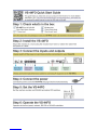
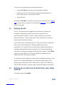
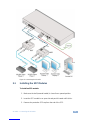
To connect the VS-44FO, do the following:
1. If SFP modules are preinstalled in your unit, go to step 4 below (and ignore
steps 1 to 3). If not, continue with step 2.
2. Insert an SFP module into each IN/OUT slot to be used (see Section 5.1).
3. Set the SFP Select button on the rear panel depending on the type of SFP
used. Press in for Non-MSA and release for MSA. The setting is saved after
powering the device ON.
4. Connect up to four fiber optic sources to the IN connectors (for example, 3G
HD-SDI video players connected to a Kramer 690T transmitter).
i
i
i
i

10
VS-44FO - Connecting the VS-44FO
5. Connect the OUT connectors to up to four fiber optic acceptors (for example,
a Kramer 690R receiver connected to 3G HD-SDI displays).
6. Set the Machine # and termination DIP-switches (see Section 5.3).
7. Optionally, connect:
A genlock source to the GENLOCK BNC connector
The LOOP BNC connector to the GENLOCK connector of the next unit
in the line, and release the TERM button for looping
Push in to terminate the input. Release when the input extends to another unit.
8. Connect a PC and/or controller (if required), to the RS-232 port (see Section
5.3), and/or the RS-485 port (see Section 5.3), and/or the Ethernet
connector (see Section 5.5).
9. Connect the power cord.
We recommend that you use only the power cord that is supplied with this machine.

VS-44FO - Connecting the VS-44FO
11
Figure 3: Connecting the VS-44FO
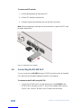
5.1 Installing the SFP Modules
To install an SFP module:
1. Make sure the bail (removal handle) is closed in an upward position.
2. Insert the SFP module in an open slot and push it inward until it clicks.
3. Remove the protective SFP cap from the end of the SFP.

12
VS-44FO - Connecting the VS-44FO
To remove an SFP module:
1. Pull the bail downward to release the SFP.
2. Pull the SFP module out by the bail.
3. If needed, replace the protective cap over the fiber connectors.
Note: When transporting or storing an unconnected device, replace the SFP caps
to protect against dust.
Figure 4: Installing the SFP Modules
5.2 Connecting the RS-232 Port
You can connect to the VS-44FO using an RS-232 connection using, for example,
a PC. Note that a null-modem adapter/connection is not required.
To connect to the VS-44FO using RS-232:
Connect the RS-232 9-pin D-sub rear panel port on the VS-44FO to the
RS-232 9-pin D-sub port on your PC. Use a 9-wire straight cable (only pin
2 to pin 2, pin 3 to pin 3, and pin 5 to pin 5 need to be connected)

VS-44FO - Connecting the VS-44FO
13
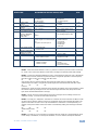
5.2.1 Determining the Machine Number
Each unit must be identified by a unique machine number (MACH #). Determine
the machine number according to the following table.
When using a single unit, set the unit to Machine # 1.
A master unit must be Machine #1.
When connecting more than one VS-44FO, set a different Machine # for each unit.
The units do not have to be numbered sequentially but each unit must have a
unique machine number.
Mach #
DIP-SWITCH
1
2
3
4
1 (Single or
master unit)
OFF
ON
OFF
OFF
OFF
OFF
OFF
OFF
2
OFF
ON
OFF
OFF
3
ON
ON
OFF
OFF
4
OFF
OFF
ON
OFF
5
ON
OFF
ON
OFF
6
OFF
ON
ON
OFF
7
ON
ON
ON
OFF
8
OFF
OFF
OFF
ON
9
ON
OFF
OFF
ON
10
OFF
ON
OFF
ON
11
ON
ON
OFF
ON
12
OFF
OFF
ON
ON
13
ON
OFF
ON
ON
14
OFF
ON
ON
ON
15
ON
ON
ON
ON
After changing the address, reset the device by turning it OFF and ON.
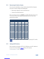
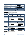
5.2.2 Setting the DIP-Switches
When controlling a unit using the RS-232 or RS-485 ports, set the DIP-switches on
the rear of the unit accordingly. Figure 5 defines the DIP-switches.
The default address is 0. All DIP-switches are OFF.
i

14
VS-44FO - Connecting the VS-44FO
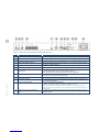
Figure 5: DIP-Switch Settings
DIPS
Function
Description
RS-485 TERM
RS-485 line
termination
OFF for no RS-485 line termination
ON for RS-485 120 line termination
PROG
Firmware update
Set ON only to update device firmware
MACH # 1, 2, 3, 4
Self Address
Sets the MACHINE # (see Section 5.3.1)
The RS-485 TERM DIP-switch is used only when the RS-485 port is connected
(see Section 5.3). The first and last units on the RS-485 line (for example, the
controller and the last VS-44FO) must be terminated. The units in between must
not be terminated.
Set the PROG DIP-switch ON only while updating the unit firmware, otherwise the
switch must be OFF.
5.3 Connecting a PC or Controller to the RS-485 Port
You can operate the VS-44FO over the RS-485 port from a distance of up to 1200
meters (3900ft) using any device equipped with an RS-485 port (for example, a
PC). For successful communication, you must set the RS-485 machine number
and bus termination.
To connect a device with a RS-485 port to the VS-44FO:
On the PC, connect the A (+) pin on the RS-485 port to the A (+) pin on the
RS-485 port on the rear panel of the VS-44FO
On the PC, connect the B (–) pin on the RS-485 port to the B (–) pin on the
RS-485 port on the rear panel of the VS-44FO
On the PC, connect the G pin on the RS-485 port to the G pin on the RS-485
port on the rear panel of the VS-44FO

VS-44FO - Connecting the VS-44FO
15
5.3.1 Setting the Machine Number Switches
To set the MACH # DIP-switches, as shown in Section 5.2.2:
For a master machine, assign MACH #1 with the address 0 (0000) or
1 (0001) set in the DIP-switches
For the slave units, assign a unique MACH # from 2 to 15 for each VS-44FO
slave. The units do not have to be sequentially numbered but they must
have unique addresses
5.3.2 Setting the Line Termination
To ensure correct operation, the RS-485 line must be terminated at both ends.
The master unit may be located at any part of the line, but when it is at the end of
the line, the termination switch must be set ON.
To set line termination, as shown in Figure 5:
For the VS-44FO units located at the ends of the RS-485 line, set the
RS-485 TERM DIP-switch ON
For all other VS-44FO units in the middle of the line, set the RS-485 TERM
DIP-switch OFF
5.4 Switching Genlocked Video Signals
The genlock feature lets you switch genlocked video signals according to the
timing of the GENLOCK reference input.
According to SMPTE RP-168, the sources must be genlocked to the GENLOCK input in order
to switch cleanly.
1. Connect the GENLOCK cable.
2. To set the genlock timing, press and hold for 3 seconds the appropriate input
button as follows:
To Set
Press and Hold
for 3 Seconds
Setting
Displayed
1080i @60Hz
IN 1
1080 60H
1080i/p @50Hz
IN 2
1080 50H
720p @60Hz
IN 3
720P 60H
PAL @50Hz
IN 4
PAL 50H
NTSC @60Hz
IN 1 & IN 2 together
NTSC 60H

16
VS-44FO - Connecting the VS-44FO
Note: When turning the machine ON, the last stored setup is shown in the
7-segment display.
5.5 Connecting the Ethernet Port
You can connect the VS-44FO over the Ethernet in the following ways:
For direct connection to the PC, use a crossover cable (see Section 5.5.1)
For connection using a network hub or network router, use a straight-through
cable (see Section 5.5.2)
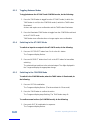
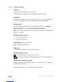
5.5.1 Connecting the Ethernet Port Directly to a PC (Crossover
Cable)
You can connect the Ethernet port of the VS-44FO to the Ethernet port on your PC,
via a crossover cable with RJ-45 connectors.
This type of connection is recommended for identifying the VS-44FO
with the factory configured default IP address.
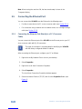
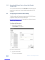
After connecting the Ethernet port, configure your PC as follows:
1. Right-click the My Network Places icon on your desktop.
2. Select Properties.
3. Right-click Local Area Connection Properties.
4. Select Properties.
The Local Area Connection Properties window appears.
5. Select the Internet Protocol (TCP/IP) and click the Properties Button (see
Figure 6).
i

VS-44FO - Connecting the VS-44FO
17
Figure 6: Local Area Connection Properties Window
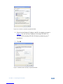
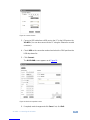
6. Select Use the following IP Address, and fill in the details as shown in
Figure 7. You can use any IP address in the range 192.168.1.1 to
192.168.1.255 (excluding 192.168.1.39) that is provided by your IT
department.
7. Click OK.
Figure 7: Internet Protocol (TCP/IP) Properties Window
Page is loading ...
Page is loading ...
Page is loading ...
Page is loading ...
Page is loading ...
Page is loading ...
Page is loading ...
Page is loading ...
Page is loading ...
Page is loading ...
Page is loading ...
Page is loading ...
Page is loading ...
Page is loading ...
Page is loading ...
Page is loading ...
Page is loading ...
Page is loading ...
Page is loading ...
Page is loading ...
Page is loading ...
Page is loading ...
Page is loading ...
-
 1
1
-
 2
2
-
 3
3
-
 4
4
-
 5
5
-
 6
6
-
 7
7
-
 8
8
-
 9
9
-
 10
10
-
 11
11
-
 12
12
-
 13
13
-
 14
14
-
 15
15
-
 16
16
-
 17
17
-
 18
18
-
 19
19
-
 20
20
-
 21
21
-
 22
22
-
 23
23
-
 24
24
-
 25
25
-
 26
26
-
 27
27
-
 28
28
-
 29
29
-
 30
30
-
 31
31
-
 32
32
-
 33
33
-
 34
34
-
 35
35
-
 36
36
-
 37
37
-
 38
38
-
 39
39
-
 40
40
-
 41
41
-
 42
42
-
 43
43


Ask a question and I''ll find the answer in the document
Finding information in a document is now easier with AI
Related papers
Other documents
-
Kramer Electronics VS-88HDXL User manual
-
-
 S&S Research VM4HD Installation and User Manual
-
-
-
Crestron USB-SW-400 User manual
-
-
-
-
