
NOTE
In order to accommodate clearer type, larger charts and graphs, and more
detailed illustrations, this edition of the TIO-540 Operator’s Manual,
Lycoming Part Number 60297-23A is presented in an 8-1/2 x 11 inch
format. This edition is a complete manual of all TIO-540 model engines
that employ angle valve cylinder heads. These Lycoming engines are TIO-
540-A1A, -A1B, -A2A, -A2B, -A2C, -F2BD, -J2B, -J2BD, -N2BD,
-R2AD, -S1AD, -U2A, -V2AD, -W2A, -AH1A and -AJ1A. This manual is
current as of the date of issue. All previously issued revisions are included.
This manual will be kept current by revisions available from Lycoming
distributors or from the factory. All revisions will be accompanied by an
Operator’s Manual Revision page which will identify the revision level, the
date of the revision, and the pages revised, added or deleted. All revisions
will be supplied in the 8-1/2 x 11 inch format.


TIO-540 Series Angle Valve Cylinder Heads Operator’s Manual
Lycoming Part Number: 60297-23A
©2005 by Lycoming. All rights reserved.
Lycoming and “Powered by Lycoming” are trademarks or registered trademarks of
Lycoming.
All brand and product names referenced in this publication are trademarks or registered
trademarks of their respective companies.
For additional information:
Mailing address:
Lycoming Engines
652 Oliver Street
Williamsport, PA 17701 U.S.A.
Phone:
Factory: 570-323-6181
Sales Department: 570-327-7268
Fax: 570-327-7101
Lycoming’s regular business hours are Monday through Friday from 8:00 AM
through 5:00 PM Eastern Time (+5 GMT)
Visit us on the World Wide Web at:
http://www.lycoming.textron.com

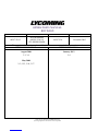
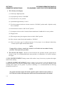
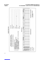
OPERATOR’S MANUAL
REVISION
REVISION NO.
PUBLICATION
PUBLICATION NO.
PUBLICATION DATE
60297-23A-3
TIO-540 SERIES
ANGLE VALVE
CYLINDER HEADS
60297-23A
November 2005
The page(s) in this revision replace, add to, or delete current pages in the operator’s manual.
PREVIOUS REVISION
CURRENT REVISION
August 2006
3-3, 3-4
May 2008
2-3; 3-55, 3-56, 3-57
January 2013
3-4
©2013 Avco Corporation, All Rights Reserved
Lycoming Engines is a division of Avco Corporation


LYCOMING OPERATOR’S MANUAL
ATTENTION
OWNERS, OPERATORS, AND
MAINTENANCE PERSONNEL
This operators manual contains a description of the engine, its specifications, and detailed information on
how to operate and maintain it. Such maintenance procedures that may be required in conjunction with
periodic inspections are also included. This manual is intended for use by owners, pilots and maintenance
personnel responsible for care of Lycoming powered aircraft. Modifications and repair procedures are
contained in Lycoming overhaul manuals; maintenance personnel should refer to these for such procedures.
SAFETY WARNING
NEGLECTING TO FOLLOW THE OPERATING INSTRUCTIONS AND TO CARRY OUT PERIODIC
MAINTENANCE PROCEDURES CAN RESULT IN POOR ENGINE PERFORMANCE AND POWER
LOSS. ALSO, IF POWER AND SPEED LIMITATIONS SPECIFIED IN THIS MANUAL ARE EXCEEDED,
FOR ANY REASON; DAMAGE TO THE ENGINE AND PERSONAL INJURY CAN HAPPEN. CONSULT
YOUR LOCAL FAA APPROVED MAINTENANCE FACILITY.
SERVICE BULLETINS, INSTRUCTIONS, AND LETTERS
Although the information contained in this manual is up-to-date at time of publication, users are urged to
keep abreast of later information through Lycoming Service Bulletins, Instructions and Service Letters
which are available from all Lycoming distributors or from the factory by subscription. Consult the latest
revision of Service Letter No. L114 for subscription information.
SPECIAL NOTE
The illustrations, pictures and drawings in this publication are typical of the subject matter they portray; in
no instance are they to be interpreted as examples of any specific engine, equipment or part thereof.
iii

LYCOMING OPERATOR’S MANUAL
IMPORTANT SAFETY NOTICE
Proper service and repair is essential to increase the safe, reliable operation of all aircraft engines. The
service procedures recommended by Lycoming are effective methods for performing service operations.
Some of these service operations require the use of tools specially designed for the task. These special tools
must be used when and as recommended.
It is important to note that most Lycoming publications contain various Warnings and Cautions which
must be carefully read in order to minimize the risk of personal injury or the use of improper service
methods that may damage the engine or render it unsafe.
It is also important to understand that these Warnings and Cautions are not all inclusive. Lycoming could
not possibly know, evaluate or advise the service trade of all conceivable ways in which service might be
done or of the possible hazardous consequences that may be involved. Accordingly, anyone who uses a
service procedure must first satisfy themselves thoroughly that neither their safety nor aircraft safety will be
jeopardized by the service procedure they select.
iv


LYCOMING OPERATOR’S MANUAL
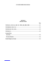
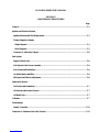
SECTION 1
DESCRIPTION
Page
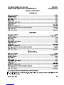
General .........................................................................................................................................................1-1
Cylinders.......................................................................................................................................................1-1
Valve Operating Mechanism ......................................................................................................................1-1
Crankcase .....................................................................................................................................................1-1
Crankshaft....................................................................................................................................................1-1
Connecting Rods ..........................................................................................................................................1-1
Pistons ...........................................................................................................................................................1-1
Accessory Housing.......................................................................................................................................1-1
Oil Sump and Induction Assembly.............................................................................................................1-2
Cooling System.............................................................................................................................................1-2
Induction System..........................................................................................................................................1-2
Turbocharger System..................................................................................................................................1-2


LYCOMING OPERATOR’S MANUAL SECTION 1
TIO-540 SERIES – ANGLE VALVE CYLINDER HEADS DESCRIPTION
SECTION 1
DESCRIPTION
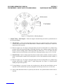
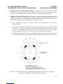
The TIO-540 series listed in this manual are six cylinder, direct drive, horizontally opposed, fuel injected,
turbocharged, air cooled engines with angle head valves.
In referring to the location of the various engine components, the parts are described in their relationship
to the engine as installed in the airframe. Thus, the power take-off end is considered the front and the
accessory drive end the rear. The sump section is considered the bottom and the opposite side of the engine
where the shroud tubes are located the top. Reference to the left and right side is made with the observer
facing the rear of the engine. The cylinders are numbered from front to rear, odd numbers on the right, even
numbers on the left. The direction of rotation for accessory drives is determined with the observer facing the
drive pad.
Cylinders The cylinders are of conventional air-cooled construction with the two major parts, head and
barrel, screwed and shrunk together. The heads are made from an aluminum alloy casting with a fully
machined combustion chamber. Rocker shaft bearing supports are cast integral with the head along with
housings to form the rocker boxes for both valve rockers. The cylinder barrels, which are machined from
chrome nickel molybdenum steel forgings, have deep integral cooling fins and the inside of the barrels are
ground and honed to a specified finish.
Valve Operating Mechanism – A conventional type camshaft is located above and parallel to the crankshaft.
The camshaft actuates hydraulic tappets which operate the valves through push rods and valve rockers. The
valve rockers are supported on full floating steel shafts. The valve springs bear against hardened steel seats
and are retained on the valve stems by means of split keys.
Crankcase – The crankcase assembly consists of two reinforced aluminum alloy castings, fastened together
by means of studs, bolts and nuts. The mating surfaces of the two castings are joined without the use of a
gasket, and the main bearing bores are machined for use of precision type main bearing inserts.
Crankshaft The crankshaft is made from a chrome nickel molybdenum steel forging. All bearing journal
surfaces are nitrided. Freedom from torsional vibration is assured by a system of pendulum type dynamic
counterweights.
Connecting Rods The connecting rods are made in the form of H section from alloy steel forgings. They
have replaceable bearing inserts in the crankshaft ends and bronze bushings in the piston ends. The bearing
caps on the crankshaft ends are retained by two bolts and nuts through each cap.
Pistons The pistons are machined from an aluminum alloy forging. The piston pin is a full floating type
with a plug located in each end of the pin. Depending on the cylinder assembly, pistons may be machined
for either three or four rings and may employ either half wedge or full wedge rings. Consult the latest
revision of Service Instruction No. 1037 for proper piston and ring combinations.
Accessory Housing The accessory housing is made from an aluminum casting and is fastened to the rear of
the crankcase and the top rear of the sump. It forms a housing for the oil pump and the various accessory
drives.
1-1

SECTION 1 LYCOMING OPERATOR’S MANUAL
DESCRIPTION TIO-540 SERIES – ANGLE VALVE CYLINDER HEADS
Oil Sump and Induction Assembly – This assembly consists of the oil sump bolted to a mated cover
containing intake pipe extensions for the induction system. When bolted together they form a mounting pad
for the air inlet housing. Fuel drain plugs are provided in the cover and the sump incorporates oil drain plugs
and an oil suction screen.
Cooling System These engines are designed to be cooled by air pressure actuated by the forward speed of
the aircraft. Baffles are provided to build up a pressure and force the air through the cylinder fins. The air is
then exhausted to the atmosphere through gills or augmentor tubes usually located at the rear of the cowling.
Induction System The Lycoming TIO-540 series employs a Bendix or Precision Airmotive (PAC) RSA
type fuel injection system.
The Bendix or PAC RSA type fuel injection system is based on the principle of measuring air flow and
using the air flow signal in a stem type regulator to convert the air force into a fuel force. This fuel force
(fuel pressure differential) when applied across the fuel metering section (jetting system) makes fuel flow
proportional to air flow.
Turbocharger System A turbocharger is mounted as an integral part of the TIO-540 series engines. The
function of the turbocharger is to provide constant air density to the fuel injector inlet from sea level to
critical altitude. Regulating the amount of exhaust gas fed to the turbine wheel controls the output which
determines engine power. This factor is regulated by the control system which has three components,
namely, the density controller, the differential pressure controller, the exhaust bypass valve (waste gate) and
the TIO-540-AJ1A engine model incorporates a Slope controller. The position of the waste gate is
determined by oil pressure acting on a piston which is connected to the butterfly valve by linkage.
Increasing oil pressure on the piston closes the waste gate valve and increases power; decreasing oil
pressure opens the valve and decreases power. The bleed oil required to activate the piston is controlled by
either the density controller or the differential pressure controller.
These controllers each act independently to regulate the pressure on the exhaust bypass piston. The
density controller regulates bleed oil at full throttle only. The differential pressure controller takes over
whenever part throttle settings are being used. If this unit was not used, the density controller would attempt
to position the exhaust bypass so that the air density at the injector entrance was always that required for
maximum power. Since this is not required for part throttle operation the differential pressure controller is
used to reduce this air pressure and allow the exhaust bypass valve to modulate over as high an operating
range as possible. The Slope controller provides constant manifold pressure from sea level to critical altitude
at full throttle and a reduced deck pressure at part throttle settings. The waste gate control is servo operated
by engine oil pressure.
NOTE
The letter “L” in the model prefix denotes the reverse rotation of the basic model. Example –
model TIO-540-F2BD has clockwise rotation of the crankshaft. Therefore, the LTIO-540-
F2BD has counterclockwise rotation. Likewise, the rotation of the accessory drives of the
LTIO-540-F2BD are opposite those of the basic model as listed in Section 2 of this manual.
The letter “D” used as the 4th or 5th character in the model suffix means that the engine is
equipped with a dual magneto housed in a single housing. Example – TIO-540-N2BD.
Operational aspects of engines are the same and performance data and specifications for the
basic model will apply.
1-2

LYCOMING OPERATOR’S MANUAL
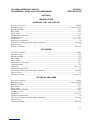
SECTION 2
SPECIFICATIONS
Page
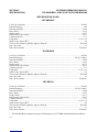
TIO-540-A1A, -A1B, -A2A, -A2B, -A2C, -F2BD, -J2B, -J2BD, -N2BD..................................................2-1
TIO-540-R2AD, -S1AD, -U2A ....................................................................................................................2-2
TIO-540-V2AD, -W2A, -AH1A ..................................................................................................................2-3
TIO-540-AJ1A..............................................................................................................................................2-4
Accessory Drives
Drive Ratio.................................................................................................................................................2-4
Direction of Rotation................................................................................................................................2-4
Standard Engine, Dry Weight ....................................................................................................................2-4


LYCOMING OPERATOR’S MANUAL SECTION 2
TIO-540 SERIES – ANGLE VALVE CYLINDER HEADS SPECIFICATIONS
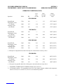
SECTION 2
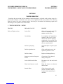
SPECIFICATIONS
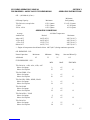
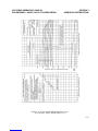
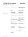
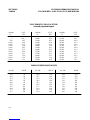
TIO-540-A1A, -A1B, -A2A, -A2B, -A2C
FAA Type Certificate ..............................................................................................................................E14EA
Rated horsepower..................................................................................................................... 310 @ 15,000 ft.
Rated speed, RPM........................................................................................................................................2575
Bore, inches.................................................................................................................................................5.125
Stroke, inches..............................................................................................................................................4.375
Displacement, cubic inches.........................................................................................................................541.5
Compression ratio ....................................................................................................................................... 7.3:1
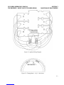
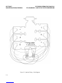
Firing order .......................................................................................................................................1-4-5-2-3-6
Spark occurs, degrees BTC..............................................................................................................................20
Valve rocker clearance (hydraulic tappets collapsed) ......................................................................... .028-.080
Prop. drive ratio ............................................................................................................................................. 1:1
Prop. driven rotation ...........................................................................................................................Clockwise
TIO-540-F2BD
FAA Type Certificate ..............................................................................................................................E14EA
Rated horsepower...........................................................................................................................................325
Rated speed, RPM........................................................................................................................................2575
Bore, inches.................................................................................................................................................5.125
Stroke, inches..............................................................................................................................................4.375
Displacement, cubic inches.........................................................................................................................541.5
Compression ratio ....................................................................................................................................... 7.3:1
Firing order .......................................................................................................................................1-4-5-2-3-6
Spark occurs, degrees BTC..............................................................................................................................20
Valve rocker clearance (hydraulic tappets collapsed) ......................................................................... .028-.080
Prop. drive ratio ............................................................................................................................................. 1:1
Prop. driven rotation ...........................................................................................................................Clockwise
TIO-540-J2B, -J2BD, -N2BD
FAA Type Certificate ..............................................................................................................................E14EA
Rated horsepower..................................................................................................................... 350 @ 15,000 ft.
Rated speed, RPM........................................................................................................................................2575
Bore, inches.................................................................................................................................................5.125
Stroke, inches..............................................................................................................................................4.375
Displacement, cubic inches.........................................................................................................................541.5
Compression ratio ....................................................................................................................................... 7.3:1
Firing order .......................................................................................................................................1-4-5-2-3-6
Spark occurs, degrees BTC..............................................................................................................................20
Valve rocker clearance (hydraulic tappets collapsed) ......................................................................... .028-.080
Prop. drive ratio ............................................................................................................................................. 1:1
Prop. driven rotation ...........................................................................................................................Clockwise
2-1

SECTION 2 LYCOMING OPERATOR’S MANUAL
SPECIFICATIONS TIO-540 SERIES – ANGLE VALVE CYLINDER HEADS
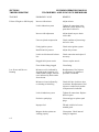
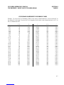
SPECIFICATIONS (CONT.)
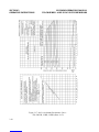
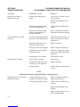
TIO-540-R2AD*
FAA Type Certificate ..............................................................................................................................E14EA
Rated horsepower...........................................................................................................................................340
Rated speed, RPM........................................................................................................................................2500
Bore, inches.................................................................................................................................................5.125
Stroke, inches..............................................................................................................................................4.375
Displacement, cubic inches.........................................................................................................................541.5
Compression ratio ....................................................................................................................................... 7.3:1
Firing order .......................................................................................................................................1-4-5-2-3-6
Spark occurs, degrees BTC..............................................................................................................................20
Valve rocker clearance (hydraulic tappets collapsed) ......................................................................... .028-.080
Prop. drive ratio ............................................................................................................................................. 1:1
Prop. driven rotation ...........................................................................................................................Clockwise
TIO-540-S1AD
FAA Type Certificate ..............................................................................................................................E14EA
Rated horsepower..................................................................................................................... 300 @ 12,000 ft.
Rated speed, RPM........................................................................................................................................2700
Bore, inches.................................................................................................................................................5.125
Stroke, inches..............................................................................................................................................4.375
Displacement, cubic inches.........................................................................................................................541.5
Compression ratio ....................................................................................................................................... 7.3:1
Firing order .......................................................................................................................................1-4-5-2-3-6
Spark occurs, degrees BTC..............................................................................................................................20
Valve rocker clearance (hydraulic tappets collapsed) ......................................................................... .028-.080
Prop. drive ratio ............................................................................................................................................. 1:1
Prop. driven rotation ...........................................................................................................................Clockwise
TIO-540-U2A
FAA Type Certificate ..............................................................................................................................E14EA
Rated horsepower..................................................................................................................... 350 @ 15,000 ft.
Rated speed, RPM........................................................................................................................................2500
Bore, inches.................................................................................................................................................5.125
Stroke, inches..............................................................................................................................................4.375
Displacement, cubic inches.........................................................................................................................541.5
Compression ratio ....................................................................................................................................... 7.3:1
Firing order .......................................................................................................................................1-4-5-2-3-6
Spark occurs, degrees BTC..............................................................................................................................20
Valve rocker clearance (hydraulic tappets collapsed) ......................................................................... .028-.080
Prop. drive ratio ............................................................................................................................................. 1:1
Prop. driven rotation ...........................................................................................................................Clockwise
* - TIO-540-R2AD has an alternate rating of 350 horsepower at 2575 RPM at standard altitude conditions.
2-2


SECTION 2 LYCOMING OPERATOR’S MANUAL
SPECIFICATIONS TIO-540 SERIES – ANGLE VALVE CYLINDER HEADS
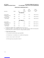
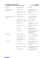
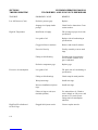
SPECIFICATIONS (CONT.)
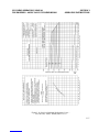
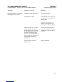
TIO-540-AJ1A
FAA Type Certificate ..............................................................................................................................E14EA
Rated horsepower..................................................................................................................... 310 @ 14,000 ft.
Rated speed, RPM........................................................................................................................................2500
Bore, inches.................................................................................................................................................5.125
Stroke, inches..............................................................................................................................................4.375
Displacement, cubic inches.........................................................................................................................541.5
Compression ratio ....................................................................................................................................... 7.3:1
Firing order .......................................................................................................................................1-4-5-2-3-6
Spark occurs, degrees BTC..............................................................................................................................20
Valve rocker clearance (hydraulic tappets collapsed) ......................................................................... .028-.080
Prop. drive ratio ............................................................................................................................................. 1:1
Prop. driven ratio ................................................................................................................................Clockwise
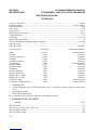
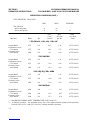
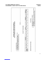
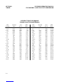
*Accessory Drive Drive Ratio **Direction of Rotation
Starter 16.556:1 Counterclockwise
Generator 1.910:1 Clockwise
Generator (Optional) 2.500:1 Clockwise
Alternator 3.200:1 Clockwise
Alternator (Optional) 3.630:1 Clockwise
Vacuum Pump 1.300:1 Counterclockwise
Hydraulic Pump 1.385:1 Clockwise
Hydraulic Pump 1.300:1 Clockwise
Tachometer .500:1 Clockwise
Propeller Governor .895:1 Clockwise
Propeller Governor .947:1 Clockwise
Magneto Drive: Single 1.500:1 Clockwise
Magneto Drive: Dual .750:1 Clockwise
Fuel Pump - AN 1.000:1 Counterclockwise
Fuel Pump Plunger Operated .500:1 Counterclockwise
* - When applicable.
** - Viewed facing drive pad NOTE that engines with L in the prefix will have opposite rotation to the
above.
- Dual magneto engines.
- Wide cylinder flange series.
- Fuel pump drive has clockwise rotation on dual magneto engines.
1. STANDARD ENGINE, DRY WEIGHT.
MODEL LBS.
TIO-540-S1AD ..............................................................................................................................................533
TIO-540-A1A, -A1B, -A2A, -A2B, -A2C.....................................................................................................537
TIO-540-AH1A, -F2BD ................................................................................................................................542
TIO-540-J2BD, -R2AD .................................................................................................................................548
2-4
Page is loading ...
Page is loading ...
Page is loading ...
Page is loading ...
Page is loading ...
Page is loading ...
Page is loading ...
Page is loading ...
Page is loading ...
Page is loading ...
Page is loading ...
Page is loading ...
Page is loading ...
Page is loading ...
Page is loading ...
Page is loading ...
Page is loading ...
Page is loading ...
Page is loading ...
Page is loading ...
Page is loading ...
Page is loading ...
Page is loading ...
Page is loading ...
Page is loading ...
Page is loading ...
Page is loading ...
Page is loading ...
Page is loading ...
Page is loading ...
Page is loading ...
Page is loading ...
Page is loading ...
Page is loading ...
Page is loading ...
Page is loading ...
Page is loading ...
Page is loading ...
Page is loading ...
Page is loading ...
Page is loading ...
Page is loading ...
Page is loading ...
Page is loading ...
Page is loading ...
Page is loading ...
Page is loading ...
Page is loading ...
Page is loading ...
Page is loading ...
Page is loading ...
Page is loading ...
Page is loading ...
Page is loading ...
Page is loading ...
Page is loading ...
Page is loading ...
Page is loading ...
Page is loading ...
Page is loading ...
Page is loading ...
Page is loading ...
Page is loading ...
Page is loading ...
Page is loading ...
Page is loading ...
Page is loading ...
Page is loading ...
Page is loading ...
Page is loading ...
Page is loading ...
Page is loading ...
Page is loading ...
Page is loading ...
Page is loading ...
Page is loading ...
Page is loading ...
Page is loading ...
Page is loading ...
Page is loading ...
Page is loading ...
Page is loading ...
Page is loading ...
Page is loading ...
Page is loading ...
Page is loading ...
Page is loading ...
Page is loading ...
Page is loading ...
Page is loading ...
Page is loading ...
Page is loading ...
Page is loading ...
Page is loading ...
Page is loading ...
Page is loading ...
Page is loading ...
Page is loading ...
Page is loading ...
Page is loading ...
Page is loading ...
Page is loading ...
Page is loading ...
Page is loading ...
Page is loading ...
Page is loading ...
Page is loading ...
Page is loading ...
Page is loading ...
Page is loading ...
Page is loading ...
Page is loading ...
Page is loading ...
Page is loading ...
Page is loading ...
Page is loading ...
Page is loading ...
Page is loading ...
-
 1
1
-
 2
2
-
 3
3
-
 4
4
-
 5
5
-
 6
6
-
 7
7
-
 8
8
-
 9
9
-
 10
10
-
 11
11
-
 12
12
-
 13
13
-
 14
14
-
 15
15
-
 16
16
-
 17
17
-
 18
18
-
 19
19
-
 20
20
-
 21
21
-
 22
22
-
 23
23
-
 24
24
-
 25
25
-
 26
26
-
 27
27
-
 28
28
-
 29
29
-
 30
30
-
 31
31
-
 32
32
-
 33
33
-
 34
34
-
 35
35
-
 36
36
-
 37
37
-
 38
38
-
 39
39
-
 40
40
-
 41
41
-
 42
42
-
 43
43
-
 44
44
-
 45
45
-
 46
46
-
 47
47
-
 48
48
-
 49
49
-
 50
50
-
 51
51
-
 52
52
-
 53
53
-
 54
54
-
 55
55
-
 56
56
-
 57
57
-
 58
58
-
 59
59
-
 60
60
-
 61
61
-
 62
62
-
 63
63
-
 64
64
-
 65
65
-
 66
66
-
 67
67
-
 68
68
-
 69
69
-
 70
70
-
 71
71
-
 72
72
-
 73
73
-
 74
74
-
 75
75
-
 76
76
-
 77
77
-
 78
78
-
 79
79
-
 80
80
-
 81
81
-
 82
82
-
 83
83
-
 84
84
-
 85
85
-
 86
86
-
 87
87
-
 88
88
-
 89
89
-
 90
90
-
 91
91
-
 92
92
-
 93
93
-
 94
94
-
 95
95
-
 96
96
-
 97
97
-
 98
98
-
 99
99
-
 100
100
-
 101
101
-
 102
102
-
 103
103
-
 104
104
-
 105
105
-
 106
106
-
 107
107
-
 108
108
-
 109
109
-
 110
110
-
 111
111
-
 112
112
-
 113
113
-
 114
114
-
 115
115
-
 116
116
-
 117
117
-
 118
118
-
 119
119
-
 120
120
-
 121
121
-
 122
122
-
 123
123
-
 124
124
-
 125
125
-
 126
126
-
 127
127
-
 128
128
-
 129
129
-
 130
130
-
 131
131
-
 132
132
-
 133
133
-
 134
134
-
 135
135
-
 136
136
-
 137
137
-
 138
138


Ask a question and I''ll find the answer in the document
Finding information in a document is now easier with AI
Related papers
Other documents
-
VEVOR JY-SA10L User manual
-
 Lancair LEGACY Pilot's Operating Handbook And Flight Manual
-
Spraying Systems CW1500A User guide
-
Cessna skylance tc T182T Information Manual
-
Mooney M20B Service And Maintenance Manual
-
Spraying Systems PW4000A User guide
-
Piper Dakota Maintenance Manual
-
-
 Scott Sport N143W Pilot Operating Handbook
-

