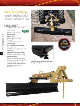
Bush Hog Rear Blade is designed to help with various tasks around your property, such as grading, leveling, and removing debris. The blade is made of durable steel and is adjustable to meet your specific needs. It also features a hydraulic system that makes it easy to operate. With its rugged construction and versatility, the Bush Hog Rear Blade is the perfect tool for any landowner or contractor.
Bush Hog Rear Blade is designed to help with various tasks around your property, such as grading, leveling, and removing debris. The blade is made of durable steel and is adjustable to meet your specific needs. It also features a hydraulic system that makes it easy to operate. With its rugged construction and versatility, the Bush Hog Rear Blade is the perfect tool for any landowner or contractor.


-
 1
1
-
 2
2
-
 3
3
-
 4
4
-
 5
5
-
 6
6
-
 7
7
-
 8
8
-
 9
9
-
 10
10
-
 11
11
-
 12
12
-
 13
13
-
 14
14
-
 15
15
-
 16
16
-
 17
17
-
 18
18
-
 19
19
-
 20
20
-
 21
21
-
 22
22
-
 23
23
-
 24
24
-
 25
25
-
 26
26
-
 27
27
-
 28
28
-
 29
29
-
 30
30
-
 31
31
-
 32
32
-
 33
33
-
 34
34
-
 35
35
-
 36
36
-
 37
37
-
 38
38
-
 39
39
-
 40
40
-
 41
41
-
 42
42
-
 43
43
-
 44
44
-
 45
45
-
 46
46
-
 47
47
-
 48
48
-
 49
49
-
 50
50
-
 51
51
-
 52
52
-
 53
53
-
 54
54
-
 55
55
-
 56
56
-
 57
57
-
 58
58


Bush Hog Rear Blade Owner's manual
- Type
- Owner's manual
- This manual is also suitable for
Bush Hog Rear Blade is designed to help with various tasks around your property, such as grading, leveling, and removing debris. The blade is made of durable steel and is adjustable to meet your specific needs. It also features a hydraulic system that makes it easy to operate. With its rugged construction and versatility, the Bush Hog Rear Blade is the perfect tool for any landowner or contractor.
Ask a question and I''ll find the answer in the document
Finding information in a document is now easier with AI
Related papers
Other documents
-
Brinly-Hardy PP-51BH User guide
-
Land Pride RBT40 Series Quick start guide
-
 Land Pride RBT40 User manual
-
Bercomac BBLST6 User manual
-
Alamo 2500 SERIES User manual
-
Alamo 800 User manual
-
Land Pride BB05 User manual
-
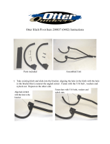 Otter Outdoors Hitch Pivot Assembly Instructions
-
 Land Pride RBT15 User manual
-
 Land Pride Rear Blades RB 15 Product information


