Page is loading ...

MF7250
1000BASE-T to 1000BASE-X
INDUSTRIAL MEDIA CONVERTER
WITH SFP SUPPORT
INSTALLATION GUIDE
© September 2006
VERSITRON, Inc.
83 Albe Drive - Suite C
Newark, DE 19702
www.versitron.com

www.versitron.com MF7250
2
PROPRIETARY DATA
All data in this manual is proprietary and may not be disclosed,
used or duplicated, for procurement or manufacturing purposes,
without prior written permission by VERSITRON, Inc.
All VERSITRON products are covered by a Lifetime Warranty against defects in materials and
workmanship. This coverage is applicable to the original purchaser and is not transferable.
We repair, or at our option, replace parts/products that, during normal usage and operation, are
proven to be defective during the time you own the products, provided that said products and
parts are still manufactured and/or available.
This warranty does not cover damage to products caused by misuse, mishandling, power surges,
accident, improper installation, neglect, alteration, improper maintenance, or other causes which
are not normal and customary application of the products and for which they were not intended.
No other warranty is expressed or implied, and VERSITRON is not liable for direct, indirect,
incidental or consequential damages or losses.
In the unlikely event a warranty issue should arise, simply contact us at 302-894-0699 or 1-800-
537-2296 or via email to [email protected] and obtain a Return Material Authorization
(RMA) number. Reference this number on the outside of the shipping container and return the
unit (shipping charges prepaid) to us for diagnostic review and repair/replacement as determined
solely by VERSITRON. We pay the shipping charges to return the repaired unit or a replacement
unit to you.

www.versitron.com MF7250
3
The information contained in this document is subject to change without prior notice. Copyright ©.
All Rights Reserved.
TRADEMARKS
Ethernet is a registered trademark of Xerox Corp.
WA R N I N G :
This equipment has been tested and found to comply with the limits for a Class A digital device,
pursuant to Part 15 of the FCC Rules. These limits are designed to provide reasonable protection
against harmful interference when the equipment is operated in a commercial environment. This
equipment generates, uses, and can radiate radio frequency energy and if not installed and used
in accordance with the instruction manual may cause harmful interference in which case the user
will be required to correct the interference at his/her own expense.
NOTICE:
(1) The changes or modifications not expressively approved by the party responsible for
compliance could void the user's authority to operate the equipment.
(2) Shielded interface cables and AC power cord, if any, must be used in order to comply with
the emission limits.
CISPR A COMPLIANCE:
This device complies with EMC directive of the European Community and meets or exceeds the
following technical standard.
EN 55022 - Limits and Methods of Measurement of Radio Interference Characteristics of
Information Technology Equipment. This device complies with CISPR Class A.
WARNING: This is a Class A product. In a domestic environment this product may cause radio
interference in which case the user may be required to take adequate measures.
CE NOTICE
Marking by the symbol
indicates compliance of this equipment to the EMC directive of the
European Community. Such marking is indicative that this equipment meets or exceeds the
following technical standards:
EN 55022: Limits and Methods of Measurement of Radio Interference characteristics of
Information Technology Equipment.
EN 50082/1: Generic Immunity Standard -Part 1: Domestic Commercial and Light Industry.
EN 60555-2: Disturbances in supply systems caused by household appliances and similar
electrical equipment - Part 2: Harmonics.

www.versitron.com MF7250
4
Table of Contents
1. Introduction...........................................................................5
1.1 Features..........................................................................................6
1.2 Specifications..................................................................................7
1.3 Special Functions..........................................................................11
2. Installation...........................................................................13
2.1 Unpacking .....................................................................................13
2.2 Safety Cautions.............................................................................14
2.3 DIN-Rail Mounting.........................................................................15
2.4 Panel Mounting .............................................................................17
2.5 Applying Power .............................................................................19
2.6 Power Failure Relay Output..........................................................22
2.7 Making Twisted Pair Copper Port Connection ..............................23
2.8 Making Fiber Port Connection.......................................................24
3 LED Indicators .....................................................................25
3.1 LED Indicators ..............................................................................25

www.versitron.com MF7250
5
1. Introduction
The industrial 1000BASE-T to 1000BASE-X media converter series provides industrial strength Ethernet copper-to-fiber media
conversion, allowing for 1000Base-T-to-1000Base-X over multi-mode or optional single-mode fiber optical
media.
For industrial environment, the converters are designed with the following enhanced features exceeding
that of commercial media converters:
• High and wide operating Temperature
• Wide operating voltage range for DC power input
• Power input interface: Industrial screw terminal block and DC power jack for external commercial
power adapter as option
• DIN rail mounting support for industrial enclosure
• Screw panel mounting support for industrial enclosure
• Industrial-rated Emission and Immunity performance

www.versitron.com MF7250
6
1.1 Features
• Gigabit copper to fiber conversion: 1000Base-T-to-1000Base-SX/LX over multimode or single-mode
fiber
• SFP design: For flexibility, an SFP (Mini-GBIC) connector is provided for the fiber port to
accommodate any type of SFP fiber transceiver when needed.
• Support full wire speed copper to fiber conversion
• Auto MDI/MDI-X detection function on the copper port
• Auto-negotiation support
• Plug and play: no configuration settings is required
• Link Fault Pass Through: this function allows link fault status passes through between copper link and
fiber link transparently.
• Far End Fault function on fiber port
• Transparent conversion to any type of packet frame
• No packet length limitation
• Diversified mounting support: desktop mounting, wall mounting, optional Din-Rail support
• Low power consumption
• Two power interface types: screw terminal block and DC jack
• Wide operating voltage input range: +7 ~ 30VDC
• Support DIN rail mounting
• Support panel mounting
• High and wide operating temperature range: -20
o
C to 70
o
C
• Industrial-rated Emission and Immunity performance

www.versitron.com MF7250
7
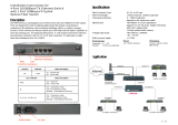
1.2 Specifications
This figure shows the important components of the converter:

www.versitron.com MF7250
8
Twisted-Pair Interface (Copper Port)
Connector Shielded RJ-45
Signal Compliance IEEE 802.3ab 1000BASE-T std.
Pin Assignments Auto MDI/MDI-X detection
Data Speed 1000Mbps
Duplex Mode Half-duplex or Full-duplex
Configuration Auto-negotiation support
Cable Types Category 5 or higher UTP
Link Distance Up to 100 meters
Fiber Optic Interface (Fiber Port)
Signal Compliance IEEE 802.3z 1000BASE-SX/LX std.
Connector SFP for pluggable fiber transceiver
Data Speed 1000Mbps
Duplex Mode Full duplex
Cable Types MMF - 50/125, 62.5/125
SMF - 9/125
Link Distance MMF up to 500m
SMF -model dependent
Eye Safety compliance IEC825 Class 1
LED Indicators
LED DISPLAY STATE INTERPRETATION
PWR Power status ON Power on
OFF Power off
SFP SFP slot status ON SFP transceiver is installed.
OFF No SFP transceiver is installed.
LINK Link status ON Copper-fiber link up
OFF Copper-fiber link down
BLINK Copper-fiber link with data traffic
OL Optical status ON Fiber port optical signal detected
OFF Fiber port no optical signal

www.versitron.com MF7250
9
DC Power Interface
Interface Screw-type terminal block
1. Two pairs for power wire cascading
2. One pair for power failure relay output
DC Jack (-D6.3mm/+D2.0mm)
Operating Input Voltages +7V ~ +30V(+5%)
Power consumption 2.25W @+7.5VDC input
2.3W @+24VDC input
2.5W @+30VDC input
Basic Information
Conversion Full wire speed
1000Mbps - 1,488,00pps at 64-byte packets
Packet Types Transparent and no modification for
- IEEE 802.3 standard packets
- IEEE 802.1Q VLAN tagged packets
Packet Length No limit
Mechanical
Dimension (base) W 28mm x D 82mm x H 95mm
Housing Enclosed metal with no fan
Mounting Support DIN-rail mounting, Panel mounting
Weight 252g
Environmental
Operating Temperature Typical -20
o
C ~ 70
o
C (model dependent)
Storage Temperature -20
o
C ~ 85
o
C
Relative Humidity 5% ~ 90%

www.versitron.com MF7250
10
Certificate
FCC Part 15 Class B
CE/EMC EMI EN50081-1 Class B
EMS EN55024
CE/LVD Safety EN 60950
EN 50081-1/1992 :
EN55022:1994/A1:1995/A2:1997
EN61000-3-2:2000
EN61000-3-3:1995/A1:2001
EN 55024:1998/A1:2001
IEC 61000-4-2:1995 ESD Test
IEC 61000-4-3:1995 RS Test
IEC 61000-4-4:1995 EFT/BURST Test
IEC 61000-4-5:1995 Surge Test
IEC 61000-4-6:1996 CS Test
IEC 61000-4-8:1993 Magnetic Field
IEC 61000-4-11:1994 Volatge Int. Dips

www.versitron.com MF7250
11
1.3 Special Functions
Auto MDI/MDI-X Function
This function allows the copper port to auto-detect the twisted-pair signals and adapts itself to form a valid
MDI to MDI-X connection with the remote connected device automatically.
Link Fault Pass Through Function
When a link fault is detected on the copper port, the device will force a link down on the fiber port
immediately. Similarly, a link fault detected on the fiber port will also force a link down on the copper port.
As illustrated in the following figure, this function allows to pass copper link fault to the remote link
partner and makes the converter like a twisted pair cable extender.

www.versitron.com MF7250
12
Far End Fault Function
The fiber port is facilitated with this function. When the fiber port detects a link failure on its receiving
circuitry, it will send out an FEFI (Far End Fault Indication) signal to the remote connected device to
indicate a remote fault is detected.
It also is capable to receive FEFI signal sent from the remote link partner if the link partner detected a
receiving fault. Upon receiving an FEFI signal, it indicates a link failure occurred on the transmitting path.
This function allows the converter to report a fiber link fault even when a link failure occurred on
transmitting fiber cable.

www.versitron.com MF7250
13
2. Installation
2.1 Unpacking
Check that the following components have been included:
• Information CD
• The Media Converter unit
• DIN-rail mounting bracket
If any item is found missing or damaged, please contact your local reseller for replacement.
The following are available optional accessories:
• Panel Mounting Bracket
The bracket is used for mounting the converter on a panel surface.
• Commercial-rated AC power adapters:
- Rated AC120V/60Hz DC7.5V 1A
- Rated AC230V/50Hz DC7.5V 1A
- Rated AC100V/50-60Hz DC7.5V 1A
- Rated AC240V/50Hz DC7.5V 1A
The adapters are used for supplying DC power to the converter
via DC power jack interface.

www.versitron.com MF7250
14
2.2 Safety Cautions
To reduce the risk of bodily injury, electrical shock, fire, and damage to the equipment, observe the
following precautions.
• Do not service any product except as explained in your system documentation.
• Opening or removing covers may expose you to electrical shock. Only a trained service technician should
service components inside these compartments.
• If any of the following conditions occur, unplug the product from the electrical outlet and replace the part
or contact your trained service provider:
- The power cable, extension cable, or plug is damaged.
- An object has fallen into the product.
- The product has been exposed to water.
- The product has been dropped or damaged.
- The product does not operate correctly when you follow the operating instructions.
• Do not push any objects into the openings of your system. Doing so can cause fire or electric shock by
shorting out interior components.
• Operate the product only from the type of external power source indicated on the electrical ratings label.
If you are not sure of the type of power source required, consult your service provider or local power
company.

www.versitron.com MF7250
15
2.3 DIN-Rail Mounting
In the product package, a DIN-rail bracket is installed on the device for mounting the converter in a
industrial DIN-rail enclosure.
The steps to mount the device onto a DIN rail are:
1. Install the mounting bracket onto the device unit as shown below:
2. Attach bracket to the lower edge of the DIN rail and push the unit upward a little bit until the bracket can
clamp on the upper edge of the DIN rail.
3. Clamp the unit to the DIN rail and make sure it is mounted securely.
4. Make sure that there are proper heat dissipation from and adequate ventilation around the device.
The final mechanical dimensions after installing DIN rail mounting bracket are:

www.versitron.com MF7250
16

www.versitron.com MF7250
17
2.4 Panel Mounting
The device is provided with an optional panel mounting bracket. The bracket supports mounting the device
on a plane surface securely. The mounting steps are:
1. Install the mounting bracket on the device unit.
2. Screw the bracket on the device unit.
3. Screw the device unit on a panel.
4. Make sure that there are proper heat dissipation from and adequate ventilation around the device. Do not
place heavy objects on the device.

www.versitron.com MF7250
18
The screw locations and final dimension are shown below:

www.versitron.com MF7250
19
2.5 Applying Power
The power specifications of the device are:
Operating Voltage +7 ~ +30VDC
Power Consumption Max. 2.5W @30VDC
The device provides two types of power interfaces, terminal block and DC power jack for receiving DC
power input from external power supply.
Using Terminal Blocks
Either DC1 interface or DC2 interface can be used to receive DC power from an external power system.
Or, DC2 also can be used to deliver the power received on DC1 to next device in cascading way.
DC1 + Vdc Positive (+) terminal
DC1 - Vdc Negative (-) terminal
DC2 + Vdc Positive (+) terminal
DC2 - Vdc Negative (-) terminal
Three 2P terminal plugs are provided together with the device. Two of the three plugs are used for DC1 and
DC2 interfaces respectively. The plug is shown below:
Power wires: 24 ~ 12AWG (IEC 0.5~2.5mm
2
)
Install the power source wires with the plug properly. Screw the wire with plug securely. Then, plug in
DC1 contacts.
If cascading the power to next device is needed, install the power wires and plug for another switch. Then,
use DC2 contacts.

www.versitron.com MF7250
20
Note: Only up to four device units can be cascaded to receive power from one main power input source.
/