Page is loading ...

Part # 464104
®
MODELS IG / IGX
Make-Up Air Unit
Installation, Operation and Maintenance Manual
Indirect Gas Fired Unit Installations
Units are listed for installation in the United States and Canada
• Installation of gas fired duct furnaces must conform with local building codes. In the absence of local
codes, installation must conform to the National Fuel Gas code, ANSI Z223.1 or in Canada,
CAN/CGA-B149 installation codes.
• All electrical wiring must be in accordance with the regulation of the National Electric Code,
ANSI/NFPA No. 70.
• Unit is approved for installation downstream from refrigeration units. In these conditions, condensate
could form in the duct furnace and provision must be made to dispose of the condensate.
**WARNING**
Improper installation, adjustment, alteration, service or maintenance can cause property damage,
injury or death. Read the installation, operating, and maintenance instructions thoroughly before
installing or servicing this equipment.
**FOR YOUR SAFETY**
The use and storage of gasoline or other
flammable vapors and liquids in open
containers in the vicinity of this appliance is
hazardous.
**FOR YOUR SAFETY**
If you smell gas:
1. Open windows.
2. Don’t touch electrical switches.
3. Extinguish any open flame.
4. Immediately call your gas supplier.
MaintenanceTroubleshootingOperationStart-UpInstallation Reference
Report any damaged equipment to the shipper immediately!
All units are shipped on a skid or packaged to minimize damage during shipment. The transporting carrier has
the responsibility of delivering all items in their original condition as received from Greenheck. The individual
receiving the equipment is responsible for inspecting the unit for obvious or hidden damage, recording any
damage on the bill of lading before acceptance and filing a claim (if required) with the final carrier. Some
accessory items are stored inside the unit during shipping. Care must be taken during installation to prevent
damage to units.

2
TABLE OF CONTENTS
STORAGE
When a unit is not going to be in service for an extended period of time, certain procedures should be followed
to keep the unit in proper operating condition:
• Plug all piping
• Rotate fan wheel monthly and purge bearings once every one to three months (depending on environment)
• Energize fan motor once every three months
• Store belts flat to keep them from warping and stretching
• Store unit in location without vibration
• Cover unit with tarp to protect from dirt and moisture
• After storage period, purge grease before putting fan into service
NOTE!
Do not cover unit with a black tarp, this would
promote condensation.
NOTE!
Improper storage which results in damage to the
unit will void the warranty.
Installation
Unit - Indoor . . . . . . . . . . . . . . . . . . . . . . . . . .3
Unit - Arrangement DB/HZ . . . . . . . . . . . . . . .4
Unit - Arrangement DBC . . . . . . . . . . . . . . .5-6
Venting - Outdoor . . . . . . . . . . . . . . . . . . . . . . .7
Venting - Indoor (All Units) . . . . . . . . . . . . . . . .8
Venting - Standard Indoor . . . . . . . . . . . . . . . .9
Venting - Concentric (General) . . . . . . . . . . .10
Venting - Concentric (Horizontal) . . . . . . .11-12
Venting - Concentric (Vertical) . . . . . . . . .13-14
Venting - Two Pipe (Horizontal) . . . . . . . .15-16
Venting - Two Pipe (Vertical) . . . . . . . . . .17-18
Electrical . . . . . . . . . . . . . . . . . . . . . . . . . .19-21
Gas Piping . . . . . . . . . . . . . . . . . . . . . . . . .22-23
Evaporative Cooler Piping . . . . . . . . . . . .24-25
Water Wizard™ Evaporative Control . . . . . .26
Direct Expansion (DX) Coil Piping . . . . . .27-29
Chilled Water Coil Piping . . . . . . . . . . . . . . . .30
Building Pressure Control . . . . . . . . . . . . . . .31
I
Start-Up
Blower . . . . . . . . . . . . . . . . . . . . . . . . . . . .32-33
Furnace (All Units) . . . . . . . . . . . . . . . . . . . . .34
Furnace (Single Stage) . . . . . . . . . . . . . . . . . .35
Furnace (2:1 Staged) . . . . . . . . . . . . . . . . . . .36
Furnace (8:1 Staged) . . . . . . . . . . . . . . . .37-41
Furnace (2:1 Modulation) . . . . . . . . . . . . . . . .42
Furnace (4:1 Modulation) . . . . . . . . . . . . .43-46
Mixing Box . . . . . . . . . . . . . . . . . . . . . . . .47-48
Water Wizard™ Evaporative Controller . .49-50
Evaporative Cooling . . . . . . . . . . . . . . . . . . . .51
S
Operation
Furnace (2:1 Staged) . . . . . . . . . . . . . . . . . . .52
Furnace (2:1 Modulation) . . . . . . . . . . . . . . . .53
4:1 Modulation / 8:1 Staged Controller . .54-55
Furnace (4:1 Modulation) . . . . . . . . . . . . . . . .56
Furnace (8:1 Staged) . . . . . . . . . . . . . . . . . . .57
Recirculating/VAV Units . . . . . . . . . . . . . . . . .58
Economizer . . . . . . . . . . . . . . . . . . . . . . . . . . .59
Water Wizard™ Evaporative Controller . . . .60
O
Troubleshooting
Blower . . . . . . . . . . . . . . . . . . . . . . . . . . . . . . .61
Motor . . . . . . . . . . . . . . . . . . . . . . . . . . . . . . .62
Airflow . . . . . . . . . . . . . . . . . . . . . . . . . . . .63-64
Vibration . . . . . . . . . . . . . . . . . . . . . . . . . . . . .65
Furnace (Single Stage or 2:1 Staged) . . . . . .66
Furnace (2:1 Modulating) . . . . . . . . . . . . . . . .67
Furnace (4:1 Modulation) . . . . . . . . . . . . .68-69
Furnace (8:1 Staged) . . . . . . . . . . . . . . . .70-71
Water Wizard™ Evaporative Controller . . . .72
T
Reference
Vent Connections . . . . . . . . . . . . . . . . . . .80-81
Model IG (Single Stage or 2:1 Staged) . . . . .82
Model IG (8:1 Staged) . . . . . . . . . . . . . . . . . .83
Model IG (2:1 Modulating) . . . . . . . . . . . . . . .84
Model IG (4:1 Modulating) . . . . . . . . . . . . . . .85
Model IGX (Blower Control Center) . . . . . . . .86
Model IGX (Single Stage or 2:1 Staged) . . . .87
Model IGX (8:1 Staged) . . . . . . . . . . . . . . . . .88
Model IGX (2:1 Modulating) . . . . . . . . . . . . . .89
Model IGX (4:1 Modulating) . . . . . . . . . . . . . .90
Performance Table . . . . . . . . . . . . . . . . . . . . .91
Warranty . . . . . . . . . . . . . . . . . . . . . .Backcover
Maintenance
Routine . . . . . . . . . . . . . . . . . . . . . . . . . . .73-75
Fall . . . . . . . . . . . . . . . . . . . . . . . . . . . . . . .76
Log . . . . . . . . . . . . . . . . . . . . . . . . . . . .77-79
M
R

3
Step 3 Install Vent Piping
Refer to the indoor venting instructions I-6. Refer to your unit submittal to determine the correct venting option.
Step 2 Install Unit
Raise the unit into place.
Using two nuts per hanger, fasten the unit supports to
hangers under the unit. Appropriate unit supports,
such as the optional Greenheck hanging bracket kit
or c-channel and angle iron (supplied by others)
should be used.
Using self tapping screws, attach ductwork to unit.
In order to prevent the unit from swinging and to
provide a safe environment for service and
maintenance, additional measures must be taken to
secure the unit in all directions.
Installation - Indoor
WARNING!
All factory provided lifting lugs must be used when lifting any unit. Failure to comply with this safety
precaution could result in property damage, serious injury or death.
Step 1 Install Hangers
Install threaded hangers from ceiling supports. When
locating hangers, allow enough room to open access
panel(s). Two nuts must be used on the end of each
threaded hanger. Ceiling supports are supplied by
others.
NOTE!
Good duct practices should be followed for all ductwork. Ductwork should be installed in accordance
with SMACNA and AMCA guidelines, NFPA 96 and any local codes. Reference the CAPS submittal for
duct sizes.
NOTE!
Vent piping is supplied by others and not supplied by Greenheck.
NOTE!
Two nuts must be used on each end of each
threaded hanging rod for proper support.
Installation
NOTE!
To prevent premature heat exchanger failure, do not locate units where chlorinated, halogenated, or
acid vapors are present.

4
Installation
Step 1 Install Curb/Equipment
Support(s)
Position curb/equipment support(s) on the roof
(reference the CAPS submittal for placement of
curb/equipment support(s) in relation to the unit).
Verify that all unit supports are level, shim if
necessary. Attach curb to roof and flash into place.
When attaching the equipment support(s) to the roof,
remove metal cover, flash to wooden nailer and
reinstall cover.
Supply Air Duct
(Arrangement DB only)
Return Air Duct
(with mixing box only)
Metal Cover
Equipment
Support
Installation - Arrangement DB / HZ
Step 2 Install Ductwork
Good duct practices should be followed for all ductwork. All ductwork should be installed in accordance with
SMACNA and AMCA guidelines, NFPA 96 and all local codes. Reference the CAPS submittal for ductwork sizes.
Step 3 Apply Sealant
Apply an appropriate sealant around the perimeter of the curb and duct adapter(s) to isolate fan vibration and
prevent water penetration.
Step 4 Install Unit
Use a crane and a set of spreader bars hooked to the
factory lifting lugs to lift and center the unit on the
curb/equipment support(s).
Use self-tapping sheet metal screws to fasten the unit
to the curb/equipment support(s).
NOTE!
The use of a duct adapter is recommended on a
downblast (DB) arrangement to align the
ductwork with the supply unit and is only a guide
and is not support for the ductwork.
NOTE!
The use of all lifting lugs and a set of spreader
bars is mandatory when lifting the unit.
NOTE!
Be sure to complete the outdoor venting
installation instructions.
NOTE!
Refer to the outdoor venting instructions when
locating the unit.

5
Supply
Ductwork
by Others
Exhaust
Ductwork
by Others
Metal Cover
Equipment
Support
Roof Curb
Exhaust
Supply
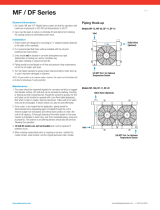
1 inch Inside
Flange
Installation - Arrangement DBC
Step 1 Install Curb/Equipment
Support(s)
Position curb/equipment support(s) on the roof
(reference the CAPS submittal for placement of
curb/equipment support(s) in relation to the unit).
Verify that all unit supports are level, shim if
necessary. Attach curb to roof and flash into place.
Attach the equipment support(s) to the roof, remove
metal cover, flash to wooden nailer and reinstall
cover.
Step 2 Install Combination Extension
Install combination extension over curb. Lag into
place using wood screws. Locate the extension so
the tall, vented-side is over the exhaust opening.
NOTE!
The use of a duct adapter is recommended on a downblast (DBC) arrangement to align the ductwork
with the supply unit and is only a guide and is not support for the ductwork.
Step 3 Install Ductwork
Good duct practices should be followed for all
ductwork. All ductwork should be installed in
accordance with SMACNA and AMCA guidelines,
NFPA 96 and any local codes. Reference the CAPS
submittal for ductwork size and location.
Installation
NOTE!
Refer to the outdoor venting instructions when locating the unit.

6
Installation
Model CUBE
Exhaust Fan
Installation - Roof Mounted Unit Arrangement DBC
Step 5 Install Exhaust Fan
Fasten exhaust fan to curb extension with self-
tapping sheet metal screws.
Step 6 Install Exhaust Options
Install optional Greenheck hinge kit with restraining cables and grease trap with drain connection.
Step 7 Install Supply Unit
Use a crane and a set of spreader bars hooked to the
factory lifting lugs to lift and center the unit on the
curb/equipment support(s).
Use self-tapping sheet metal screws to fasten the unit
to the curb/equipment support(s).
NOTE!
Installing the exhaust fan prior to the supply unit
will allow for easier installation of options.
NOTE!
The use of all lifting lugs and a set of spreader
bars is mandatory when lifting unit.
NOTE!
Be sure to complete the outdoor venting
installation instructions.
Supply Duct with Duct
Adapter Installed
Exhaust Duct Installed
Sealant
Step 4 Apply Sealant
Apply an appropriate sealant around the perimeter of
the curb and duct adapter(s) to isolate fan vibration
and prevent water penetration.

7
Installation - Venting for Outdoor Units
WARNING!
Do not install units in locations where flue products can be drawn into adjacent building openings
such as windows, fresh air intakes, etc. Distance from vent terminal to adjacent public walkways,
adjacent buildings, operable windows, and building openings shall conform with the local codes. In the
absence of local codes, installation shall conform with the National Fuel Gas Code, ANSI Z223.1, or the
CAN/CGA B-149 Installation Codes.
WARNING!
The following guidelines must be followed for all outdoor units:
1. Building materials that will be affected by flue gases should be protected.
2. Maintain minimum horizontal clearance of 4 feet from electric meters, gas meters, regulators,
and relief equipment. In Canada, the minimum clearance is 6 feet.
3. The combustion blower discharge on outdoor units must be located a minimum of 42 inches
from any combustible materials.
4. Do not modify or obstruct the combustion air inlet cover or the combustion blower
weatherhood.
5. Do not add vents other than those supplied by the manufacturer.
6. During the winter, keep the unit clear of snow to prevent any blockage of the combustion
venting.
NOTE!
Clearances from combustible material for indoor units are determined by the National Fuel Gas Code
and/or other local codes.
Step 1 Follow Guidelines
All of the following guidelines must be followed when installing the unit.
Step 2 Install Stack (Optional)
Clearance may require an exhaust stack. Install an exhaust stack as needed to the exhaust connection on the
unit. Install a vent terminal on the exhaust pipe.
Installation

8
Installation - Venting for All Indoor Units
NOTE!
The drip leg should be cleaned out periodically during the heating season.
Venting Methods
There are three venting method for indoor mounted units. Specific venting instructions are provided for each
method. Refer to the specific instructions for the venting method listed in the CAPS submittal.
The venting method options are:
• Standard Indoor Venting (uses building air for combustion, vents outdoors, one roof or wall penetration)
• Separated Combustion 2-Pipe Venting (uses outside air for combustion, vents outdoor, two exterior roof or
wall penetrations)
• Separated Combustion Concentric Venting (uses outside air for combustion, vents outdoors, one exterior roof
or wall penetration)
NOTE!
For each method, the units can be vented horizontally through an exterior wall or vertically through the
roof. Refer to the specific venting instructions for your unit. Construct the vent system as shown in
these instructions.
NOTE!
Vent piping is supplied by others and not supplied by Greenheck.
Installation
WARNING!
The following guidelines must be followed for all indoor units:
1. Installation of venting must conform with local building codes. In the absence of local codes,
installation must conform with the National Fuel Gas Code, ANSI Z223.1 or in Canada,
CAN/CGA-B149 installations codes.
2. For the exhaust pipe, use pipe approved for a category III appliance or single wall, 26 gauge or
heavier galvanized vent pipe. The piping is required to be gas tight by ANSI.
3. For the combustion air pipe on separated combustion units, sealed single-wall galvanized air
pipe is recommended.
4. The joints must be sealed with a metallic tape or silastic suitable for temperatures up to 350ºF.
5. A minimum of 12 inches of straight vent pipe is recommended after the exhaust connection and
before any elbows.
6. Vertical combustion air pipes should be fitted with a tee, drip leg and clean-out cap to prevent
any moisture in the combustion air pipe from entering the unit.
7. To reduce condensation, insulate any vent runs greater than 5 feet.
8. All vent pipe connections should be made with at least three corrosion resistant sheet metal
screws.
9. Refer to the National Fuel Gas Code for additional piping guidelines.

9
Standard Horizontal Venting
A = 12 in. minimum
A
Pitch vent pipe
downward from
furnace
1
⁄4
inches per foot
Exhaust Vent
Terminal
EXHAUST
Exterior Wall
Air Inlet
Step 1 Select Vent Pipe Size
Select the vent pipe size from the table to the right.
Use only the specified pipe size.
Step 2 Install Exhaust Vent Pipe
Install the vent pipe with minimum downward slope (from the unit) of
1
⁄4 inch per foot. Securely suspend the pipe
from overhead structures at points no greater than 3 feet apart. Attach the vent terminal to the end of the
exhaust pipe.
Installation - Standard Indoor Venting
NOTE!
Standard indoor venting uses one penetration through an exterior wall or roof for venting the flue
exhaust. The combustion air is supplied from the air inside the building. Units must not be installed in
a potentially explosive, flammable, or corrosive atmosphere. To prevent premature heat exchanger
failure, do not locate units where chlorinated, halogenated, or acid vapors are present.
NOTE!
When units are installed in tightly sealed
buildings, provisions should be made to supply
adequate amount of infiltration air from the
outside. The rule of thumb is that an opening of
one square inch should be provided for every
1000 BTU per hour of input rating.
IMPORTANT!
Vent terminals must be used. Construct the vent
system as shown in drawings and reference the
tables for the correct vent pipe diameters. The
minimum vent length is 5 feet for horizontal and
10 feet for vertical. The maximum vent length is
70 feet. The total equivalent vent length must
include elbows. The equivalent length of a 4 inch
elbow is 6 feet and the equivalent length of a 6
inch elbow is 10 feet.
Standard Vertical Venting
B
A = 12 inch minimum
B = 12 inch minimum,
but should size
according to
expected snow
depth.
EXHAUST
Exhaust Vent
Terminal
Air Inlet
Roof Line
A
Furnace Exhaust Pipe
Size (MBH) Diameter
75-175 4 inches
200-400 6 inches
Installation

10
WARNING!
The concentric venting adapter is designed for indoor installations and should never be installed on
the exterior of the building.
Installation - Concentric Venting (General)
NOTE!
Concentric venting allows the exhaust pipe and combustion air pipe to pass through a single hole in
the roof or wall of the building. A concentric venting adapter is required for concentric venting.
NOTE!
If venting vertically through the roof, refer to the vertical concentric venting instructions. If venting
horizontally through the wall, refer to the horizontal concentric venting instructions.
CVA-4
(4 inch Concentric Venting Adapter)
CVA-6
(6 inch Concentric Venting Adapter)
Exhaust Connection
Concentric Side
Combustion Air Connection
Concentric Side
Exhaust Connection
Non-Concentric Side
Combustion Air Connection
Non-Concentric Side
CVA
NOTE!
The exhaust pipe must terminate with the vent terminal. The combustion air pipe must terminate with
the combustion air guard (horizontal venting) or terminal (vertical venting). Both are provided in the
optional venting kit along with the concentric venting adapter (CVA).
NOTE!
Vent piping is supplied by others and not supplied by Greenheck.
Installation

11
Step 1 Determine Venting Location
Determine the location of the concentric venting adapter (CVA) based on any clearances that must be maintained
(follow all codes referenced in these instructions).
Step 2 Attach Mounting Brackets
Attach field supplied, corrosion resistant mounting brackets to the CVA using corrosion resistant sheet metal
screws.
Installation - Concentric Venting (Horizontal)
EXHAUST
COMBUSTION AIR
Exterior Wall
Mounting
Bracket
Mounting
Bracket
A
B
Exhaust Pipe
Terminal
A = 2 inch minimum
B = 12 inch minimum
Combustion Air
Inlet Guard
Pitch vent pipe downward from
furnace .25 inches per foot
NOTE!
All vent piping is FIELD SUPPLIED by others and
is not supplied by Greenheck.
NOTE!
The optional venting kit includes a concentric
venting adapter (CVA), vent terminal and guard.
NOTE!
Maintain at least 12 inches from the combustion air inlet guard to the vent terminal.
NOTE!
To prevent water from running into the combustion air pipe and to allow for easy installation of the
combustion air guard, the combustion air pipe must terminate at least 2 inches from the exterior
surface of the outside wall.
Non-Concentric Concentric
Vent Connection Diameter Vent Connection Diameter
Furnace Size Exhaust Combustion Exhaust Combustion
(MBH) (Inches) Air (Inches) (Inches) Air (Inches)
75 -175 4446
200 -400 6668
Installation
IMPORTANT!
Vent terminals must be used. Construct the vent system as shown in drawings and reference the
tables for the correct vent pipe diameters. The minimum vent length is 5 feet and the maximum vent
length is 70 feet. The total equivalent vent length must include elbows. The equivalent length of a 4
inch elbow is 6 feet and the equivalent length of a 6 inch elbow is 10 feet.

12
Step 4 Install Combustion Air Pipe
Attach a field supplied combustion air pipe to the
concentric side of the CVA.
Be sure to provide enough combustion air piping to
pass through the wall and provide the minimum
clearance of 2 inches between the combustion air
intake and the exterior surface of the outside wall.
Be sure to maintain the minimum clearance of 12
inches between the exhaust pipe termination and the
combustion air intake.
Step 5 Install CVA Assembly
Place the entire CVA assembly through the wall and verify that all minimum clearance requirements as specified
in these instructions are met. Secure the CVA assembly to the wall with corrosion resistant sheet metal screws
through the mounting brackets.
Step 6 Attach CVA Assembly to Unit
Attach the exhaust pipe to the unit’s combustion exhaust. Using an additional combustion air pipe, connect the
unit’s combustion air supply intake to the combustion air connection on the CVA.
Step 8 Seal Opening
Seal the opening between the wall and the air intake pipe using an appropriate method.
Step 7 Install Combustion Air Inlet Guard and Exhaust Vent Terminal
Slide the combustion air inlet guard over the exhaust pipe and fasten it to the combustion air pipe. Attach the
exhaust vent terminal to the discharge end of the exhaust piping on the outside of the building.
Step 3 Install Exhaust Pipe
Slide the exhaust pipe through the CVA.
Be sure to provide enough exhaust piping to pass
through the wall and provide the minimum clearance
of 12 inches between the exhaust pipe termination
and the combustion air intake.
With all required clearances satisfied, attach the
exhaust pipe to the CVA.
Installation - Concentric Venting (Horizontal)
Exhaust
Connection
(Model IG)
Exhaust
Connection
(Model IGX)
Combustion Air
Connection
(Model IG)
Combustion Air
Connection
(Model IGX)
Installation
Intake End
Discharge
End

13
Installation - Concentric Venting (Vertical)
NOTE!
All vent piping is FIELD SUPPLIED by others.
Exhaust Vent Terminal
Combustion Air
Inlet Terminal
A
C
C
B
Roofline
EXHAUST
COMBUSTION AIR
Tee with drip leg and
cleanout cap
A = 12 inch minimum, but should size
according to expected snow depth.
B = 12 inch minimum
C = 12 inch minimum
NOTE!
Maintain at least 12 inches of clearance between
the top of the combustion air inlet terminals and
the bottom of the exhaust terminal.
NOTE!
A tee with clean-out must be provided on the combustion air and exhaust pipe to prevent debris from
entering the heat exchanger.
NOTE!
The bottom of the combustion air intake pipe
must terminate above the snow line, or at least
12 inches above the roof, whichever is greater.
Mounting
Bracket
Mounting
Bracket
Step 1 Determine Venting Location
Determine the location of the concentric venting adapter (CVA) based on any clearances that must be maintained
(follow all codes referenced in these instructions).
Step 2 Attach Mounting Brackets
Attach field supplied corrosion resistant mounting brackets to the CVA.
NOTE!
The optional venting kit includes a concentric
venting adapter (CVA), and two terminals.
Installation
IMPORTANT!
Vent terminals must be used. Construct the vent system as shown in drawings and reference the
tables for the correct vent pipe diameters. The minimum vent length is 10 feet and the maximum vent
length is 70 feet. The total equivalent vent length must include elbows. The equivalent length of a
4 inch elbow is 6 feet and the equivalent length of a 6 inch elbow is 10 feet.
Non-Concentric Concentric
Vent Connection Diameter Vent Connection Diameter
Furnace Size Exhaust Combustion Exhaust Combustion
(MBH) (inches) Air (inches) (inches) Air (Inches)
75 -175 4446
200 -400 6668

14
Installation - Concentric Venting (Vertical)
Step 3 Install Exhaust Pipe
Slide the exhaust pipe through the CVA.
Be sure to provide enough exhaust piping to pass
through the roof and provide the minimum clearance
of 12 inches between the exhaust pipe termination
and the combustion air intake.
With all required clearances satisfied, attach the
exhaust pipe to the CVA.
Step 4 Install Combustion Air Pipe
Attach a field supplied combustion air pipe to the
concentric side of the CVA. Be sure to provide enough
combustion air piping to pass through the roof and
provide the minimum clearance of 12 inches between
the combustion air intake and the exterior surface of
the roof. This clearance may need to be increased to
allow for snow accumulation. Be sure to maintain the
minimum clearance of 12 inches between the exhaust
pipe termination and the combustion air intake.
Step 5 Install CVA Assembly
Place the entire CVA assembly through the roof and verify that all minimum clearance requirements as specified
in these instructions are met. Secure the CVA assembly to the ceiling with corrosion resistant sheet metal screws
through the mounting brackets.
Step 6 Attach CVA Assembly to Unit
Attach the exhaust pipe to the unit’s combustion exhaust. Using an additional combustion air pipe, connect the
unit’s combustion air supply intake to the combustion air connection on the CVA. Be sure to include the required
tee’s with drip legs and clean outs.
Step 8 Seal Opening
Seal the opening between the roof and the air intake pipe using an appropriate method.
Step 7 Install Terminals
Slide the combustion air terminal over the vent pipe and fasten it to the combustion air pipe. Attach the exhaust
vent terminal to the discharge end of the exhaust piping.
Installation
Exhaust
Connection
(Model IG)
Exhaust
Connection
(Model IGX)
Combustion Air
Connection
(Model IG)
Combustion Air
Connection
(Model IGX)
Intake End
Discharge
End

15
Exterior Wall
B
A
EXHAUST
COMBUSTION AIR
Pitch vent pipe downward from
furnace
1
⁄4 inches per foot
C
Field Supplied
Support Brackets
A = 12 inch minimum
B = 24 inch minimum
C = 12 inch minimum
Exhaust Vent
Terminal
Combustion Air
Inlet Terminal
Installation - Two Pipe Venting (Horizontal)
NOTE!
All vent piping is FIELD SUPPLIED by others.
NOTE!
Maintain at least 12 inches of clearance between
the exhaust pipe termination and the exterior
surface of the exterior wall.
NOTE!
The combustion air pipe must be a minimum of
12 inches from the exhaust pipe and 24 inches
from the exterior surface of the outside wall.
NOTE!
Optional venting kit includes two vent terminals.
Installation
NOTE!
A minimum of 1 inch and a maximum of 48 inch of building wall thickness is required for separated
combustion vent pipe.
IMPORTANT!
Vent terminals must be used. Construct the vent system as shown in drawings and reference the
tables for the correct vent pipe diameters. The minimum vent length is 5 feet and the maximum vent
length is 50 feet. The total equivalent vent length must include elbows. The equivalent length of a
4 inch elbow is 6 feet and the equivalent length of a 6 inch elbow is 10 feet.
Vent Connection Diameter
Furnace Size Exhaust Combustion
(MBH) (Inches) Air (Inches)
75 - 175 4 4
200 - 400 6 6

16
Step 1 Install Exhaust Pipe
Run an exhaust pipe from the unit’s combustion
exhaust through the exterior wall to the outdoors. The
exhaust pipe must terminate at least 12 inches from
the outside surface of the outside wall. Attach exhaust
vent terminal to the end of the exhaust pipe. Using
field supplied mounting brackets, support the exhaust
pipe as needed.
Step 3 Seal Wall Openings
Using an appropriate method, seal the wall openings around the piping.
Step 2 Install Combustion Air Pipe
Run a combustion air pipe from the unit’s combustion
air intake through the exterior wall to the outdoors.
The combustion air pipe must terminate at least 12
inches from the combustion vent pipe and 24 inches
from the exterior surface of the outside wall. Attach
the combustion air inlet guard to the end of the
combustion air pipe. Using field supplied mounting
brackets, support the combustion air pipe as needed.
Installation - Two Pipe Venting (Horizontal)
Installation
Exhaust
Connection
(Model IG)
Exhaust
Connection
(Model IGX)
Combustion Air
Connection
(Model IG)
Combustion Air
Connection
(Model IGX)
Intake End
Discharge
End

17
C
D
D
B
A
A = 12 inch minimum, but should size
according to expected snow depth.
B = 24 inch minimum
C = 12 inch minimum
D = 12 inch minimum
EXHAUST
COMBUSTION AIR
Tee with drip leg and
clean-out cap.
Combustion Air
Inlet Terminal
Exhaust Vent
Terminal
Installation - Two Pipe Venting (Vertical)
NOTE!
The combustion air pipe must terminate at least
12 inches above the roof. This clearance may
need to be increased to accommodate for snow
accumulation.
NOTE!
The exhaust must terminate at least 12 inches
above and 12 inches horizontally from the
combustion air inlet.
NOTE!
All vent piping is FIELD SUPPLIED by others.
NOTE!
The optional vent kit includes two terminals.
Installation
IMPORTANT!
Vent terminals must be used. Construct the vent system as shown in drawings and reference the
tables for the correct vent pipe diameters. The minimum vent length is 10 feet and the maximum vent
length is 70 feet. The total equivalent vent length must include elbows. The equivalent length of a
4 inch elbow is 6 feet and the equivalent length of a 6 inch elbow is 10 feet.
Vent Connection Diameter
Furnace Size Exhaust Combustion
(MBH) (Inches) Air (Inches)
75 - 175 4 4
200 - 400 6 6

18
Installation
Step 1 Install Exhaust Pipe
Run an exhaust pipe from the unit’s combustion
exhaust through the roof to the outdoors. The exhaust
pipe must terminate at least 12 inches above the
outside surface of the roof. This clearance may need
to be increased to accommodate snow accumulation.
Attach the exhaust vent terminal to the end of the
exhaust pipe.
Step 3 Seal Roof Penetration
Using an appropriate method, seal the roof openings around the vent pipes.
Step 2 Install Combustion Air Pipe
Run a combustion air pipe from the unit’s combustion
air intake through the roof to the outdoors. The
combustion air pipe must terminate at least 12 inches
horizontally and vertically from the combustion
exhaust pipe and at least 24 inches from the exterior
surface of the roof. These clearances may need to be
increased to accommodate for expected snow
accumulation. Attach the combustion air terminal to
the end of the combustion air pipe.
Installation - Two Pipe Venting (Vertical)
Exhaust
Connection
(Model IG)
Exhaust
Connection
(Model IGX)
Combustion Air
Connection
(Model IG)
Combustion Air
Connection
(Model IGX)
Intake End
Discharge
End

19
Installation - Electrical Wiring
CAUTION!
If replacement wire is required, it must have a
temperature rating of at least 105°C, except for
energy cut-off or sensor lead wire which must be
rated to 150°C.
CAUTION!
Any wiring deviations may result in personal injury or property damage. Greenheck is not responsible
for any damage to, or failure of the unit caused by incorrect final wiring.
DANGER!
High voltage electrical input is needed for this
equipment. This work should be performed by a
qualified electrician.
IMPORTANT!
All wiring should be done in accordance with the
latest edition of the National Electric Code
ANSI/NFPA-70 and any local codes that may
apply. In Canada, wiring should be done in
accordance with the Canadian Electrical Code.
IMPORTANT!
The equipment must be properly grounded.
Any wiring running through the unit in the
airstream must be protected by metal conduit,
metal clad cable or raceways.
IMPORTANT!
Before connecting power to the unit, read and understand the following instructions and wiring
diagrams. Complete wiring diagrams are attached on the inside of the control center door(s).
IMPORTANT!
Greenheck’s standard control voltage is 24 VAC.
Control wire resistance should not exceed 0.75 ohms (approximately 285 feet total length for 14 gauge
wire; 455 feet total length for 12 gauge wire). If the resistance exceeds 0.75 ohms an industrial-style,
plug-in relay should be wired in place of the remote switch. The relay must be rated for at least 5
amps and have a 24 VAC coil. Failure to comply with these guidelines may cause motor starters to
chatter or not pull in, resulting in contactor failures and/or motor failures.
Step 3 Connect the Main Power
Connect the main power lines to the disconnect switch and main grounding lug(s). Torque field connections to
20 in-lbs. See the blower control center layout in the reference section for main disconnect and grounding lug(s)
locations.
Step 1 Determine the Size of the Main
Power Lines
The unit nameplate states the voltage and the unit’s
total amps. The main power lines to the unit should
be sized accordingly.
Step 2 Provide the Opening(s) for the
Electrical Connections
Electrical openings vary by unit size and arrangement
and are field supplied.
MODEL
VOLTS
SUP HP
MARK
AMPS
HTZ PH
S/N
EXH HP
Voltage, Hertz,
and Phase
Unit’s Total
Amps
Installation

20
Installation
Step 5 Wire the Accessories
Reference the ladder diagram in the control center for
correct wiring of the following accessories:
Step 6 Wire Optional Evaporative Cooler
Reference the ladder diagram on the inside of the control center door for correct wiring of the pump and the
optional auto-drain and flush. If the Water Wizard was selected, the temperature sensor may need to be wired,
refer to the Water Wizard start-up.
Step 7 Install Optional Economizer Sensors
All economizer options (EC) require an outdoor air temperature or enthalpy sensor to be field installed inside of
the weatherhood and field wired to terminals SO+ and SO- on the economizer.
Economizer options EC-3 and EC-4 require an outdoor air temperature or enthalpy sensor to be field installed in
the return air duct and field wired to terminals SR+ and SR- on the economizer.
The sensors are provided by the factory and ship with the unit.
NOTE!
Large evaporative coolers may require a separate power supply.
NOTE!
The TSCP and KSCP remote panels have number-to-number wiring.
NOTE!
Wiring to the Selectrastat or room override
should be in separate conduit or run with
shielded cable.
Installation - Electrical Wiring
• Selectrastat
• Room Override
• Blower Switch
• Heat Switch
• Indicating Lights
• Dirty Filter Indicator
• TSCP
• KSCP
• Mixing Box Actuator
• Room Stat
Step 4 Wire the Convenience Outlet (Optional)
The optional convenience outlet requires a separate 115V power supply circuit with short circuit protection by
others.
/