Page is loading ...

INSTALLATION INSTRUCTIONS
Step & Brick Lights
1625 Surveyor Avenue • Simi Valley, CA 93063 • (805) 527-0987 • (800) 766-VISTA (8478)
FAX: (888) 670-VISTA (8478) • [email protected] • www.vistapro.com
12V SERIES
FOR USE ONLY WITH LOW VOLTAGE LANDSCAPE POWER UNITS THAT DO NOT EXCEED 25 AMPS, 15 VOLT MAXIMUM.
WARNING: Luminaires must be installed in accordance with the National Electrical Code (NEC) and local codes. Failure to do so will void the
warranty and may result in serious injury and/or damage to the luminaire.
SAFETY WARNING: Luminaire can become very hot depending on lamp wattage used. Lens and metal around lamp can become hot enough to
blister hands. Particular care should be taken not to locate luminaires where small children can reach them if high wattage lamps are used.
LUMINAIRES ARE NOT TO BE INSTALLED WITHIN 10 FT. (3.05M) OF A POOL OR SPA. SECONDARY CABLE IS NOT TO BE BURIED MORE THAN 6”. WHEN USING
MULTIPLE LUMINAIRES, LOAD IS NOT TO EXCEED THE TOTAL WATTS OF TRANSFORMER RATING. DO NOT USE EXTENSION CORDS ON POWER UNITS.
NOTE: Always use UL recognized wire connectors for connections.
NOTE: Save these instructions for future reference.
LUMINAIRE IS UL LISTED FOR ABOVE GROUND INSTALLATION ONLY.
4246
Vista Professional Outdoor Lighting reserves the right to modify the design and/or construction of the xture shown without further notication.
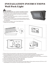
Wood
Staircase
18-2 Pigtail
Main Supply
Cable
Adjustable Nylon Mount
Can Slide Up and Down to
Compensate Tilting of Housing
Cover
Screws
Reflector
Retaining Screw
Bracket
Screw
Washer
Slide to Adjust
Cover Alignment
Flexible or PVC
Conduit (by others)
Frame
Mounting
Bracket
Reflector
Fixture Cover
Mounting
Wood Screw
LUMINAIRE MOUNTING FOR EXISTING WALLS/WOOD DECKS:
1. To prevent electrical shock, disconnect transformer from electrical
supply before installation or service.
2. Remove reector assembly from luminaire.
3. Using luminaire housing as a template, mark location of housing on
wall or deck.
4. Cut hole in wall or deck to accept housing and insert housing.
NOTE: Remove insulation within 6” of where luminaire will be mounted.
5. Using frame mounting brackets, bracket screws and mounting wood
screws (provided), secure housing tightly against wall or deck.
6. Using two blue wire nut connectors (provided), connect wire leads
from behind reector to 18-2 cable pigtail (provided) exiting luminaire.
7. Install reector and lamp.
8. Prior to installing cover plate, make necessary adjustments to nylon
mounts to correct any tilt of housing.
9. Install cover plate to luminaire and tighten screws evenly.
10. Strip two leads from luminaire wire. Using silicone lled safety
connectors (provided), connect leads from luminaire to main supply
cable leads.
11. Provide power to luminaire and check for proper operation.
LUMINAIRE MOUNTING FOR MASONRY/CONCRETE WALLS:
1. Remove reector assembly from luminaire.
2. Using standard masonry procedures, build wood support frame and
secure luminaire to support frame.
NOTE: Optional mounting brackets for some models are available to
facilitate installation in concrete walls.
NOTE: UL listed exible conduit is recommended for connections to ease
luminaire position and adjustment during installation.
3. Remove ½” knockout from side or bottom of luminaire.
4. Connect conduit (by others), pull supply wires through into housing.
5. Cover opening of luminaire with cardboard, be sure unused electrical
plugs (knockouts) are closed before concrete pour.
6. Pour concrete using standard masonry procedures.
7. Using UL listed wire nut connectors (provided), connect wire leads from
behind reector to 18-2 cable pigtail (provided) exiting luminaire.
8. Install reector and lamp.
9. Prior to installing cover plate, make necessary adjustments to nylon
mounts to correct any tilt of housing.
10. Install cover plate to luminaire and tighten screws evenly.
11. Using two blue wire nut connectors (provided), connect wire leads
from behind reector to 18-2 cable pigtail (provided) exiting luminaire.
12. Provide power to luminaire and check for proper operation.

1625 Surveyor Avenue • Simi Valley, CA 93063 • (805) 527-0987 • (800) 766-VISTA (8478)
FAX: (888) 670-VISTA (8478) • [email protected] • www.vistapro.com
Vista Professional Outdoor Lighting reserves the right to modify the design and/or construction of the xture shown without further notication.
4246 (06/10)
The operating voltage range for this LED luminaire is 6 - 15 volt AC. The Vista electronic driver ensures the LED operates at the intended lumen output
while receiving voltage as low as 6 volts, and as high as 15 VAC, resulting in a balanced lumen output from the rst xture to the last. Eliminating the
dimness issues often attributed to voltage drop.
Note: Operating voltage range for LED luminaries will vary depending on model, style and total number of LEDs. To help determine the operating
voltage range for each Vista luminaire, always consult factory’s specication sheet and/or installation instructions before installation.
COVER
SCREWS
LED ENGINE
ASSEMBLY
ADUSTABLE
NYLON MOUNT
SLIDE TO ADJUST
COVER ALIGNMENT
FRAME
MOUNTING
BRACKET
WASHER
BRACKET SCREW
FIELD REPLACEABLE
DRIVER ASSEMBLY
FIELD REPLACEABLE
LED BOARD
FIXTURE COVER
OPTICAL FILTER
FEMALE CONNECTOR
MALE CONNECTOR
FLEXIBLE OR PVC
CONDUIT (BY OTHERS)
Wood
Staircase
18-2 Pigtail
Main Supply
Cable
LED ENGINE INSTALLATION/REPLACEMENT:
1. To prevent electrical shock, disconnect transformer from electrical supply before service.
2. Remove stainless steel screws holding xture cover and lens to xture and remove cover.
3. Remove eld replaceable LED engine from LED bracket.
4. Disconnect connector assembly.
5. Connect new eld replaceable LED engine to connector assembly.
6. Reinstall LED engine assembly into LED bracket.
7. Reinstall lens and cover, fastening with stainless steel screws.
WARNING: TO REDUCE THE RISK OF FIRE, OR INJURY TO PERSONS:
1. Turn off/unplug and allow to cool before replacing lamp.
2. Lamps get hot quickly! Contact only switch/plug when turning on.
3. Do not touch hot lens, guard or enclosure.
4. Keep lamp away from material that may burn.
5. Do not touch the lamp at any time. Use a soft cloth. Oil from the skin
may damage lamp.
6. Do not operate luminaire tting with a missing or damaged cover.
IMPORTANT SAFETY INSTRUCTIONS - THE LIGHTED LAMP IS HOT!
SAVE THESE INSTRUCTIONS
(Leave with property owner/manager)
LAMP INSTALLATION/REPLACEMENT:
CAUTION: Do not exceed maximum wattage marked on luminaire label.
1. To prevent electrical shock, disconnect transformer from electrical supply before service.
2. Loosen cover screws and remove cover.
3. Replace lamp with correct wattage and type marked on xture label.
NOTE: DO NOT touch Halogen lamp with bare hands. Always use soft cloth or the plastic wrapping (if available) from the lamp to handle the lamp.
4. Reinstall cover and tighten the cover screws evenly.
LED:
/