
1
LCD Projector Commercial Use
Operating Instructions
PT-L6510E
PT-L6600E
Model No.
Read these instructions completely before operating this unit.
TQBJ 0119
ENGLISH
ITALIANO ESPAÑOL FRANÇAIS DEUTSCH

2
WARNING:
1) Remove the plug from the wall outlet when this unitis not in use for a prolonged period of
time.
2) To prevent electric shock, do not remove cover. No user serviceable parts inside. Refer
servicing to qualified service personnel.
3) Do not remove the earthing pin on the power plug. This apparatus is equipped with a three
prong earthing-type power plug. This plug will only fit an earthing-type power outlet. This is
a safety feature. If you are unable to insert the plug into the outlet, contact an electrician.
Do not defeat the purpose of the eanhing plug.
Dear Panasonic Customer:
This instruction booklet provides all the necessary operating information that you might require.
We hope it will help you to get the most performance out of your new product, and that you will
be pleased with your Panasonic LCD projector.
The serial number of your product may be found on its back. You should note it in the space
provided below and retain this booklet in case service is required.
Model number: PT-L6510E / PT-L6600E
Serial number:
IMPORTANT SAFETY NOTICE
WARNING: THIS APPARATUS MUST BE EARTHED.
Machine Noise lnformation Ordinance 3. GSGV, January 18 1991: The sound pressure level
at the operator position is equal or less than 70 dB (A) according to ISO 7779.
WARNING: To prevent damage which may result in fire or shock hazard, do not expose
this appliance to rain or moisture.

3
ENGLISH
lMPORTANT: THE MOULDED PLUG (U.K. only)
FOR YOUR SAFETY, PLEASE READ THE FOLLOWING TEXT CAREFULLY.
This appliance is supplied with a moutded three pin mains plug for your safety and convenience.
A 13 amp fuse is fitted in this plug. Should the fuse need to be replaced, please ensure that the
replacement fuse has a rating of 13 amps and that it is approved by ASTA or BSl to BS1362.
Cheque for the ASTA mark or the BSl mark on the body of the fuse.
lf the plug contains a removable fuse cover, you must ensure that it is refitted when the fuse is
replaced. lf you lose the fuse cover, the plug must not be used until a replacement cover is
obtained. A replacement fuse cover can be purchased from an Authorized Service Centre.
If the fitted moulded plug is unsuitable for the socket outlet in your home, then the fuse
should be removed and the plug cut off and disposed of safely. There is a danger of severe
electrical shock if the cut off plug is inserted into any 13 amp socket.
If a new plug is to be fitted, please observe the wiring code as shown below.
If in any doubt, please consult a qualified electrician.
WARNING: –THIS APPLIANCE MUST BE EARTHED.
IMPORTANT: –The wires in this mains lead are coloured in accordance
with the following code: –
Green-and-Yellow: Earth
Blue: Neutral
Brown: Live
As the colours of the wire in the mains lead of this appliance may not correspond with the
coloured markings identifying the terminals in your plug, proceed as follows.
The wire which is coloured GREEN-AND-YELLOW must be connected to the terminal in
the plug which is marked with the letter E or by the Earth symbol or coloured GREEN or
GREEN-AND-YELLOW.
The wire which is coloured BLUE must be connected to the terminal in the plug which is
marked with the letter N or coloured BLACK.
The wire which is coloured BROWN must be connected to the terminal in the plug which is
marked with the letter L or coloured RED.
How to replace the fuse. Open the fuse compartment with
a screwdriver and replace the fuse.
FUSE

4
IMPORTANT SAFETY NOTICE ......................... 2
Precautions with regard to safety ................... 5
WARNING .......................................................................5
Caution ............................................................................6
Accessories ....................................................... 7
Precautions on handling .................................. 8
Example of System up...................................... 9
Location and function of each part ............... 10
Remote control ..............................................................10
Projector <Top·Front and Side> ....................................11
Projector <Top·Rear and Side> .....................................12
Projector <Rear control panel> .....................................12
Projector <Interface panel> ...........................................13
Using the Remote control unit....................... 14
Loading batteries...........................................................14
Effective control range...................................................14
Using laser pointer ........................................................15
Setting projector IDs for remote control.........................15
Using the remote control as a PC mouse......................16
Using the remote control in wired mode........................17
Setting-up ........................................................ 18
Projection Schemes ......................................................18
Installation Geometry ....................................................18
Projection Distances......................................................18
Setup precautions .........................................................19
Example of connecting with AV products ......................20
Example of connecting with PCs...................................21
Example of connecting with system switcher ................22
Starting to use ................................................. 23
Powering Up the Projector ............................................23
Making Initial Adjustment / Settings input port...............23
Powering Off the Projector ............................................23
Leveling the Projector....................................................24
Adjusting the Vertical Position of the Picture.................24
Advice on the installation of exhaust guides .................25
Using the Freeze function .............................. 25
Using the Shutter function ............................. 25
Using the Digital Zoom function.................... 26
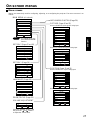
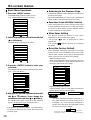
On-screen menus............................................ 27
Menu screens................................................................27
Basic Menu Operations .................................................28
Returning to the Previous Page ....................................28
Menu Items Shown with White Characters ...................28
Menu Items Setting .......................................................28
Reset the Factory Default..............................................28
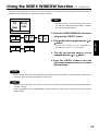
Using the INDEX WINDOW function.............. 29
Adjusting the picture ...................................... 30
PICTURE MODE...........................................................30
COLOUR .......................................................................30
TINT ..............................................................................30
BRIGHT.........................................................................30
CONTRAST...................................................................30
SHARPNESS ................................................................30
TV-SYSTEM ..................................................................31
Contents
W·BAL R/G/B.................................................................31
SIGNAL MODE..............................................................31
STANDARD...................................................................31
Adjusting the position .................................... 32
HORIZONTAL POSITION .............................................32
VERTICAL POSITION...................................................32
VIDEO SIZE ..................................................................32
DOT CLK .......................................................................32
CLK PHASE ..................................................................32
KEYSTONE...................................................................32
V. LINEARITY................................................................32
ASPECT ........................................................................33
STANDARD...................................................................33
Adjusting the Zoom/Focus............................. 33
ZOOM............................................................................33
FOCUS..........................................................................33
Changing the display language ..................... 33
OPTION 1 settings........................................... 34
OSD (On-Screen Display) .............................................34
RGB FORMAT...............................................................34
LENS SHIFT..................................................................34
BACK COLOUR ............................................................34
PROJECTION SCHEME 1............................................34
PROJECTION SCHEME 2............................................34
OPTION 2 settings........................................... 35
LAMP POWER ..............................................................35
LAMP SELECT..............................................................35
LAMP RUNTIME ...........................................................35
SETTING FUNCTION 1 [FUNC 1] ................................35
SETTING UNIT ID .........................................................36
Registering / Deleting / Displaying User Mode..............36
Using the SERIAL............................................ 37
Connection ....................................................................37
Pin assignments and signal names...............................37
Communication requirements .......................................37
Basic format ..................................................................37
Control command ..........................................................38
Cable specifications ......................................................38
USB control ...................................................................38
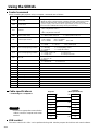
Using the remote terminal.............................. 39
Indication of lamp monitor ............................. 40
Cleaning and replacing the air filter .............. 41
Cleaning method ...........................................................41
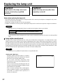
Replacing the lamp unit.................................. 42
Lamp replacement period..............................................42
Lamp unit replacement steps ........................................43
Before asking for service ............................... 45
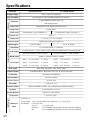
Specifications.................................................. 46
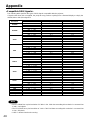
Appendix.......................................................... 48
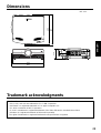
Dimensions...................................................... 49
Trademark acknowledgments........................ 49

5
ENGLISH
Precautions with regard to safety
WARNING
If a problem occurs (such as no image or no sound) or if you notice smoke or a strange
smell coming from the projector, turn off the power and disconnect the power cord from the
wall outlet.
• Do not continue to use the projector in such cases, otherwise fire or electric shocks could result.
• Cheque that no more smoke is coming out, and then contact an Authorized Service Centre for repairs.
• Do not attempt to repair the projector yourself, as this can be dangerous.
Do not install this projector in a place which is not strong enough to take the full weight of
the projector.
• If the installation location is not strong enough, it may fall down or tip over, and severe injury or damage could result.
• Installation work (such as ceiling suspension) should only be carried out by a qualified technician.
• If installation is not carried out correctly, there is the danger that injury or electric shocks may occur.
If foreign objects or water get inside the projector, or if the projector is dropped or the
cabinet is broken, turn off the power and disconnect the power cord from the wall outlet.
• Continued use of the projector in this condition may result in fire or electric shocks.
• Contact an Authorized Service Centre for repairs.
Do not cover the air filter, the air inlet and exhust vents.
• Doing so may cause the projector to overheat, which can cause fire or damage to the projector.
Do not overload the wall outlet.
• If the power supply is overloaded (for example, by using too many adapters), overheating may occur and fire may
result.
Do not remove the cover or modify it in any way.
• High voltages which can cause fire or electric shocks are present inside the projector.
• For any inspection, adjustment and repair work, please contact an Authorized Service Centre.
Clean the power cord plug regularly to prevent it from becoming covered in dust.
• If dust builds up on the power cord plug, the resulting humidity can damage the insulation, which could result in fire.
Pull the power cord out from the wall outlet and wipe it with a dry cloth.
• If not using the projector for an extended period of time, pull the power cord plug out from the wall outlet.
Do not do anything that might damage the power cord or the power cord plug.
• Do not damage the power cord, make any modifications to it, place it near any hot objects, bend it excessively, twist
it, pull it, place heavy objects on top of it or wrap it into a bundle.
• If the power cord is used while damaged, electric Shocks, short-circuits or fire may result.
• Ask an Authorized Service Centre to carry out any repairs to the power cord that might be necessary.
Do not handle the power cord plug with wet hands.
• Failure to observe this may result in electric shocks.
Insert the power cord plug securely into the wall outlet.
• If the plug is not inserted correctly, electric shocks or overheating could result.
• Do not use plugs which are damaged or wall outlets which are coming loose from the wall.
Do not place the projector on top of surfaces which are unstable.
• If the projector is placed on top of a surface which is sloped or unstable, it may fall down or tip over, and injury or
damage could result.
Do not place the projector into water or let it become wet.
• Failure to observe this may result in fire or electric shocks.

6
Do not place liquid containers on top of the projector.
• If water spills onto the projector or gets inside it, fire or electric shocks could result.
• If any water gets inside the projector, contact an Authorized Service Centre.
Do not insert any foreign objects into the projector.
• Do not insert any metal objects or flammable objects into the projector or drop them onto the projector, as doing so
can result in fire or electric shocks.
After removing the battery from remote control unit, keep it away from the reach of children.
• The battery can cause death by suffocation if swallowed.
• If the battery is swallowed, seek medical advice immediately.
Do not allow the + and - terminals of the battery to come into contact with metallic objects
such as necklaces or hairpins.
• Failure to observe this may cause the battery to leak, overheat, explode or catch fire.
• Store the battery in a plastic bag and keep it away from metallic objects.
Insulate the battery using tape or similar before disposal.
• If the battery comes into contact with metallic objects or other batteries, it may catch fire or explode.
A child in not made to use remote control and do not look into the laser beam emitted from
the remote control.
• Although laser emission from the remote control is not harmful to human health, do not look directly into the laser
beam or aim it at another person.
• Laser radiation can cause injury to the human eye.
Caution
Do not set up the projector in humid or dusty places or in places where the projector may
come into contact with smoke or steam.
• Using the projector under such conditions may result in fire or electric shocks.
When disconnecting the power cord, hold the plug, not the cord.
• If the power cord itself is pulled, the cord will become damaged, and fire, short-circuits or serious electric shocks
may result.
Always disconnect all cables before moving the projector.
• Moving the projector with cables still attached can damage the cables, which could cause fire or electric shocks to
occur.
Do not place any heavy objects on top of the projector.
• Failure to observe this may cause the projector to become unbalanced and fall, which could result in damage or
injury.
Do not short-circuit, heat or disassemble the battery or place it into water or fire.
• Failure to observe this may cause the battery to overheat, leak, explode or catch fire, and burns or other injury may
result.
When inserting the battery, make sure the polarities (+ and -) are correct.
• If the battery is inserted incorrectly, it may explode or leak, and fire, injury or contamination of the battery compartment
and surrounding area may result.
Use only the Specified battery.
• If an incorrect battery is used, it may explode or leak, and fire, injury or contamination of the battery compartment
and surrounding area may result close to this port, otherwise burns or damage could result.
Precautions with regard to safety

7
ENGLISH
Do not look into the lens while the projector is being used.
• Strong light is emitted from the projector’s lens. If you look directly into this light, it can hurt and damage your eyes.
Do not bring your hands or other objects close to the air outlet port.
• Heated air comes out of the air outlet port. Do not bring your hands or face, or objects which cannot withstand heat.
Replacement of the lamp unit should only be carried out by a qualified technician.
• The lamp unit has high internal pressure. It can easily become damaged if struck against hard objects or dropped,
and injury or malfunctions may result.
Replacement of the lamp unit should only be carried out after it has completely cooled off,
otherwise burns may result.
Disconnect the power cord plug from the wall outlet as a safety precaution before carrying
out any cleaning.
• Electric shocks can result if this is not done.
Ask an Authorized Service Centre to clean inside the projector at least once a year.
• If dust is left to build up inside the projector without being cleaned out, it can result in fire or problems with operation.
• It is a good idea to clean the inside of the projector before the season for humid weather arrives. Ask your nearest
Authorized Service Centre to clean the projector when required. Please discuss with the Authorized Service Centre
regarding cleaning costs.
Do not reach for the openings beside the optical lens, during horizontal or vertical movements
of the lens there is a injury hazard.
An effort to keep our environment clean, Please bring the non repairable unit your Dealer or
a Recycling Company.
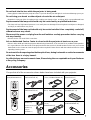
Accessories
Cheque that all of the accessories shown below have been included with your projector.
Remote control unit
[N2QAEA000003 x1]
Battery for remote control unit
[R03NPE/2ST x1]
Lens cover
[TKKL5103 x1]
RGB signal cable (for VGA)
[3.0 m,
K1HB15FA0001 x1
]
Wired cable for remote control
[15 m, K1EA03NA0001 x1]
USB cable
[3.0 m, K1HB04FD0002 x1]
Conversion plug
[K2RB031D0001 x1]
Power cord for U. K.
[TXFSX02VTHZ x1]
Power cord for Continental
[TXFSX02VTFZ x1]
Right-side exhaust guide
[TPAKK21 x1]
Left-side exhaust guide
[TPAKK22 x1]
Fixing pin
[TPAMM33 x1]

8
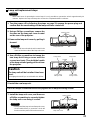
Cautions regarding transportation
Be sure to attach the lens cover before transporting the
projector.
The projection lens is extremely susceptible to vibration
and shocks. When carrying the projector, be careful not to
subject to excessive vibration or shock while under
transport.
Cautions regarding setting-up
Observe the following at all times when setting up the
projector.
Avoid setting up in places which are subject to
vibration or shocks.
If the projector is set up in locations with strong vibration,
such as near a motor, or if it is installed inside a vehicle or
on board a ship, the projector may be subjected to vibration
or shocks which can damage the internal parts and cause
malfunctions or accidents. Accordingly, set up the projector
in a place which is free from such vibrations and shocks.
Do not set up the projector near high-voltage power
lines or near motors.
The projector may be subject to electromagnetic
interference if it is set up near high-voltage power lines or
motors.
If installing the projector to the ceiling, ask a qualified
technician to carry out all installation work.
If the projector is to be suspended from the ceiling, you
will need to purchase the separate installation kit (Model
No.: ET-PKL6500/S). Furthermore, all installation work
should only be carried out by a qualified technician.
This product cannot be used at altitudes of 1,400 m or
more above sea level. If it is used as is, there may be an
adverse effect on component service life and so on.
Notes on use
If using this projector more than 8hours/day (continuous
operation), special measures will be necessary to use
this projector. Please consult your dealer or Authorized
Service Centre about preparations.
In order to get the best picture quality
If outside light or light from indoor lamps is shining onto
the screen, the images projected will not have good
contrast. Draw curtains or blinds over any windows and
turn off any fluorescent lights near the screen to prevent
reflection.
Depending on the environment where used, hot air from
the cooling fan vent may in rare cases cause disturbances
on the screen.
Do not touch the surfaces of the lens with your bare
hands.
If the surface of the lens becomes dirty from fingerprints
or anything else, this will be magnified and projected onto
Before carrying out cleaning and
maintenance, be sure to disconnect the
power cord plug from the wall outlet.
Wipe the cabinet with a soft, dry cloth.
If the cabinet is particularly dirty, soak the cloth in water
with a small amount of neutral detergent in it, squeeze
the cloth very well, and then wipe the cabinet. After
cleaning, wipe the cabinet dry with a dry cloth.
If using a chemically-treated cloth, read the
instructions supplied with the cloth before use.
Do not wipe the lens with a cloth that is dusty or which
produces lint.
If any dust or lint gets onto the lens, such dust or lint
will be magnified and projected onto the screen. Use
a blower to clean any dust and lint from the lens
surface, or use a soft cloth to wipe off any dust or lint.
Precautions on handling
the screen. Moreover, when not using the projector, cover
it with the accessory lens cover.
About the screen
If the screen you are using is dirty, damaged or discolored,
attractive projections cannot be obtained. Do not apply
any volatile substances to the screen, and do not let it
become dirty or damaged.
Lamp
A mercury lamp with high internal pressure is used as the
light source for this equipment. High-pressure mercury
lamps have the following characteristics.
• If the lamp deteriorates due to shock, scratching or the
passage of time during use, it may rupture with a loud
noise, or enter the unlit state and end its service life.
• Service life varies significantly due to individual lamp
differences and use conditions.
• Exceeding the replacement period will increase the
probability of rupture.
About the liquid crystal panel
The liquid crystal panel of the projector is built with very
high precision technology giving you fine picture details.
Occasionally, a few non-active pixels may appear on the
screen as a fixed point of blue, green or red.
Please note that this dose not affect the performance of
your LCD.
About optical parts
If the projector is subjected to a continuous use for more
than 6 hours every day, you may have to replace optical
parts, such as LCD panels or polarizers within less than
one year. When you use the projector in such a case, ask
your dealer or an Authorized Service Center for details.

9
ENGLISH
REMOTERGB OUT
OUT
WIRED
IN
IN
OUTIN
R/R-Y/P
R
G/Y SYNC/HD VDB/B-Y/P
B
IN OUT
OUTIN RL
USB SERIALS-VIDEO IN AUDIO IN
RGB
AUDIO
AUDIO
VIDEO
RGB 2 IN
OUTIN
DVI-D
RGB 1 IN
> PC < TBMU152
REMOTERGB OUT
OUT
WIRED
IN
IN
OUTIN
R/R-Y/P
R
G/Y SYNC/HD VDB/B-Y/P
B
IN OUT
OUTIN RL
USB SERIALS-VIDEO IN AUDIO IN
RGB
AUDIO
AUDIO
VIDEO
RGB 2 IN
OUTIN
DVI-D
RGB 1 IN
> PC < TBMU152
Example of System up
System 1
Picture brightness can be doubled by stacking
two projectors with the stacking brackets.
System 2
The projector features a wealth of interface ports and optional parts that can be used to set up the projection
system in diverse ways. The following presents some of those setup examples:
The optional high- or low-ceiling mount bracket
flexibly fits the projector in individual site
conditions.
System 3
PCs equipped with a DVI-D port can be attached
to the projector for computer image viewing.
(Realization of high clear picture.)
System 4
A variety of video sources can be fed to the
projector through a system switcher.
O
F
F
O
F
F
P
O
W
E
R
O
N
I
N
P
U
T
S
E
L
E
C
T
1
2
3
4
5
6
V
P
O
N
/
O
F
F
S
i
g
n
a
l
S
e
l
e
c
t
o
r
T
W
-
S
W
S
J
Laser disc player
Digital STB or
DVD player
Control PC
System Switcher
(Option)
Video deck
(It is an image figure using the simple mount
bracket)
(It is an image figure using the Ceiling mount
bracket)

10
ENTER button (page 16 and 28)
Press this button to enter your menu selection or to run
functions. The button acts as the right mouse button if the
Mode switch is set to the Computer position.
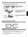
FREEZE button (page 25)
Press this button to temporarily freeze the image
presently on the screen.
SHUTTER button (page 25)
Press this button to temporarily mute/black out both
audio and video.
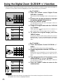
D.ZOOM (+/-) buttons (page 26)
Any portion of the picture can be enlarged.
VOLUME (+/-) buttons (page 23)
Use these buttons to adjust the volume level from the
internal speakers or line levels on the AUDIO OUT lines.
FUNC1 button (page 35)
Use to select from the functions listed on the “OPTION
2” screen that can be chosen from the MAIN MENU.
ID SET button (page 15)
Use to set the projector ID when multiple PT-L6510E/
L6600E projectors are used in the system.
Mode switch (Computer/Projector) (page 16)
When controlling the projector, set this switch to the
Projector (right) side. When controlling your PC, set
it to the Computer (left) side.
Wired Remote Control port (page 17)
When using wired remote control, connect the remote
control to the projector with the accessory wired
remote control cable.
Remote Control Transmitter Window
Whenever operating the Remote Control, aim this window
to the projector's remote control receiver window.
Laser Transmitter Window
Click button (page 16)
The button acts as the left mouse button if the Mode
switch is set to the Computer position.
Remote control operating indicator lamp
The light flashes when any remote control button other
than the “LASER” button is pressed.
POWER button (page 23)
Turns the projector ON/OFF when the MAIN POWER
switch on the projector is set to “ I ”.
AUTO SETUP button (page 23)
Pressing this button automatically corrects picture
positioning on the screen. While the auto setup
feature is active, the message “AUTO SETUP”
appears on the screen.
RGB button (page 23)
Use to toggle through the RGB1, RGB2, and DVI-D
input ports.
LASER button (page 15)
While this button is pressed and held, the remote
control activates its laser transmitter to display a laser
pointer on the screen.
VIDEO button (page 16 and 23)
Use to toggle between the Composite Video and S-
Video ports. The button acts as the Page Down button
if the Mode switch is set to the Computer position.
MENU button (pages 16, 27 and 28)
Main Menu display is switched on and off alternately
each time this button is pressed. If the menu has
multiple pages, this button may be used to view the
next or previous menu page. The button acts as the
Page Up button if the Mode switch is set to the
Computer position.
Arrow ( ) buttons (page 16 and 28)
Use to choose menu items, change settings, or adjust
control parameters. The button acts as a mouse, so
can move the cursor if the Mode switch is set to
the Computer position.
Remote Control
Location and function of each part

11
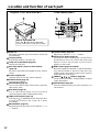
ENGLISH
Status LED lights
(Viewed from the rear side)
Remote control receiver window (page 14)
Receives IR commands transmitted from the remote
control.
Focus ring (page 23)
For focus adjustment.
Powered focus adjustment is also available.
Projection lens
Images are projected onto the screen through this
lens.
Lens cap
Cap the lens whenever the projector is left unused.
Power status light (page 23)
Lit in red when the projector is in standby mode with
MAIN POWER switch set to “ I ”. Lit in green when
the unit is turned ON.
Lamp 1 monitor (page 40)
Lights when lamp unit 1 requires replacement.
Flashes if the lamp 1 drive circuit is malfunctioning.
Lamp 2 monitor (page 40)
Lights when lamp unit 2 requires replacement.
Flashes if the lamp 2 drive circuit is malfunctioning.
Temperature (TEMP) monitor light (page 40)
Warns of unacceptable internal temperatures. May
be either continuously lit or flashing.
Speakers
Speakers deliver a total audio output power of 6 watts
(3 + 3 watts each).
Line input (AC IN) socket (page 23)
Connect the accessory line power cord into this
receptacle. Do not connect any other cord to this
socket.
MAIN POWER switch (page 23)
Use this switch to turn “ I ” “O” the commercial line
power applied to the projector.
Burglar lock
Attach a commercial burglar prevention cable (e.g.
from Kensington) to this lock port. It is compatible
with the Micro Saver Security System from
Kensington. This security lock is compatible with the
Microsaver Security System from Kensington.
Contact details for this company are given below.
Kensington Technology Group ACCO Brands Inc.
2885 Campus Drive San Mateo, CA 94403
Tel (650)572-2700
Fax (650)572-9675
http://www.kensington.com/
http://www.gravis.com/
Air filter (page 41)
Leveling button (page 24)
Use these buttons (one on each side) to level the
projector when resting on its feet.
Leveling foot (page 24)
Use in conjunction with for the projector's tilt
adjustment.
(A leveling foot is provided on each side of the unit.)
R
E
M
O
T
E
R
G
B
O
U
T
O
U
T
W
I
R
E
D
IN
IN
O
U
T
I
N
R
/
R
-Y
/P
R
G
/Y
S
Y
N
C
/H
D
V
D
B
/
B
-Y
/
P
B
IN
O
U
T
O
U
T
IN
R
L
U
S
B
S
E
R
I
A
L
S
-
V
I
D
E
O
I
N
A
U
D
I
O
I
N
R
G
B
A
U
D
I
O
A
U
D
I
O
V
I
D
E
O
R
G
B
2
I
N
O
U
T
IN
D
V
I
-
D
R
G
B
1
I
N
>
P
C
<
T
B
M
U
1
5
2
Exhaust vents
Exhaust vents
Status LED lights
Side interface panel
(see page 13)
STAND BY (R) LAMP1 LAMP2 TEMP
ON (G)
Projector < Top · Front and Side >

12
Stack Lid
When two projectors are to be stacked, use this lid
for positioning.
Carrying handle
Pull out this handle to carry the unit.
Lamp unit compartment (page 43)
Houses the lamp unit.
Rear side remote control receiver window
(page 14)
Receives commands transmitted from the remote
control.
Control subpanel lid
Open this lid to access the control subpanel.
POWER switch (page 23)
Turns the unit ON/OFF.
VIDEO button (page 23)
Use to select video signal format from composite
video and S-video.
RGB button (page 23)
Use to select RGB signal source from those
connected to the RGB1, RGB2 and DVI ports.
LENS SHIFT buttons (page 24)
Pressing the or button tilts the projection lens
to move the picture on the screen up or down
accordingly.
ZOOM buttons (page 23)
Adjust the picture size on the screen with the “ + ” or
“ – ” buttons.
FOCUS buttons (page 23)
Adjust focus with the “ + ” or “ – ” buttons.
AUTO SETUP button (page 23)
Pressing this button automatically corrects picture
positioning on the screen. While the Auto setup
feature is active, the message “AUTO SETUP”
appears on the screen.
MENU button (pages 27 and 28)
Main Menu display is switched on and off alternately
each time this button is pressed. If the menu has
multiple pages, this button can be used to view the
next or previous menu page.
ARROW ( ) buttons (page 28)
Use to choose menu items, change settings, or adjust
control parameters.
ENTER button (page 28)
Press this button to enter your menu selection or to
run functions.
How to open panel lid
Press the mark on the upper right
corner of the panel lid until it clicks open.
Projector < Top · Rear and Side >
Location and function of each part
< Rear control panel >

13
ENGLISH
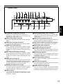
< Interface panel >
SERIAL IN port (pages 20, 21, 22 and 37)
Use the RS-232C serial port as an alternative
interface for controlling the projector from your PC.
(D-SUB 9 pin)
SERIAL OUT port (pages 21 and 22)
The signal applied to the serial input port appears at
this port (9-pin D-sub female connector).
RGB1 (YPBPR) input ports (pages 20, 21 and 22)
Apply RGB or YPBPR video to these ports. (BNC)
RGB2 (YPBPR) IN port (page 21)
RGB video input port. (D-SUB 15 pin)
RGB OUT port (pages 21 and 22)
The signals applied to RGB1 or RGB2 input ports
appear at this port (15-pin D-sub female connector).
REMOTE port (page 39)
This port may be used to control the projector from
the Remote Control set up in Wired mode. (9-pin D-
sub female connector)
DVI-D IN port (pages 19 and 21)
DVI-D signals are applied to this port. (24-pin DVI
connector)
DVI-D OUT port (page 21)
The signal applied to the DVI-D input port appears at
this port (24-pin DVI connector).
WIRED IN/OUT ports (page 17)
Use to connect multiple PT-L6510E/L6600E
projectors in a daisy chain to simultaneously control
them from a single wired remote control. (M3 jack)
S-VIDEO IN port (pages 19, 20 and 33)
Connect an S-video signal source to this port.
Depend on input signal, screen aspect will
automatically change 16:9 or 4:3.
VIDEO IN port (pages 20 and 22)
Connect a composite video signal source to this port.
(BNC)
VIDEO OUT port (pages 20 and 22)
Composite video signal appears at this port. (BNC)
AUDIO IN L-R jacks (page 20)
Only a single pair of audio inputs is available. Change
connections to these jacks according to your choice
of video source from composite and S-video (RCA
jacks).
RGB AUDIO IN jack (pages 20 and 21)
Only a single pair of audio inputs is available. Change
connections to these jacks according to your choice
of video source from RGB1, RGB2 and DVI-D (M3
jacks).
AUDIO OUT jack (page 20)
The audio signals applied to the AUDIO IN or RGB
AUDIO IN jacks of this unit appear at this jack. Once
a cable is plugged into this jack, the signal lines to
the internal speakers are cut off. (M3 jack)
USB IN ports (pages 16, 21 and 38)
The remote control can be used as your PC mouse
by connecting the projector to your PC with the
supplied USB cable. (4-pin square connector)
USB OUT ports
The control ports on two or more projectors can be
connected to each other for interlocked control
operations. (Type B)
REMOTERGB OUT
OUT
WIRED
IN
IN
OUTIN
R/R-Y/P
R G/Y SYNC/HD VDB/B-Y/PB
IN OUT
OUT
OUT
IN RL
USB SERIALS-VIDEO IN AUDIO IN
RGB
AUDIO
AUDIO
VIDEO
RGB 2 IN
OUTIN
DVI-D
RGB 1 IN
> PC < TBMU152

14
projector
Screen
Remote control
receiver window
(Front)
Remote control
receiver window
(Rear)
Remote
control
REMOTERGB OUT
OUT
WIRED
IN
IN
OUTIN
R/R-Y/P
R
G/Y SYNC/HD VDB/B-Y/P
B
IN OUT
OUTIN RL
USB SERIALS-VIDEO IN AUDIO IN
RGB
AUDIO
AUDIO
VIDEO
RGB 2 IN
OUTIN
DVI-D
RGB 1 IN
> PC < TBMU152
OUT
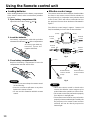
Using the Remote control unit
Loading batteries
When loading batteries into the battery compartment
of the remote control, make sure that their polarities
are correct.
1. Open battery compartment lid.
Open lid in the order of steps and .
2. Insert the batteries
Into battery compartment, with their polarities
orientated as indicated ( / ) in the compartment.
3. Close battery compartment lid.
Replace the battery compartment lid over the
compartment and slide until it clicks.
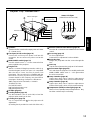
Effective control range
The remote control should normally be aimed at either
the front or rear remote control receiver window on
the projector (fig. 1). Otherwise it may also be aimed
at the screen, which will reflect commands back to
the projector's front receiver window as illustrated in
figure 2.
The effective control range is approx. 7 metres (23
feet) immediately in front of the receiver windows.
fig. 1
Accessory type-AAA dry
batteries (insert the
negative side first).
REMOTERGB OUT
OUT
WIRED
IN
IN
OUTIN
R/R-Y/P
R
G/Y SYNC/HD VDB/B-Y/P
B
IN OUT
OUTIN RL
USB SERIALS-VIDEO IN AUDIO IN
RGB
AUDIO
AUDIO
VIDEO
RGB 2 IN
OUTIN
DVI-D
RGB 1 IN
> PC < TBMU152
OUT
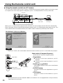
(Front)
15°
15°
15°
15°
30°
30°
30°
30°
(Rear)
[Top view]
[Side view]
Remote
control
Remote
control
Remote
control
Remote
control
Caution
• Exercise care not to drop the remote control
on hard flooring.
• Exercise care not to spill water or any other
liquid on the remote control.
• Do not use Ni-Cd batteries with this remote
control.
Note
• When the remote control is aimed at the
screen, the effective control range may be
reduced due to the optical loss of the screen.
• The remote control may not function properly
if an object is in the light path.
• The remote control receiver may not function
properly in intense ambient light. Carefully site
the projector so its remote control receiver
windows will not be directly exposed to
intense light.
fig. 2

15
ENGLISH
PUSH
LASER RADIATION
DO NOT STARE INTO BEAM
WAVE LENGHT: 640-660nm
MAXIMUM OUTPUT: 1mW
CLASS II LASER PRODUCT
PRODUCT COMPLIES WITH DHHS RULES 21 CFR SUBCHAPTER J
IN EFFECT AS OF DATE OF MANUFACTURE.
MANUFACTURER: MANUFACTURED:
LASER RADIATION
DO NOT STARE INTO BEAM
CLASS 2 LASER PRODUCT
IEC60825–1:1993+A1:1997
EN60825–1:1994+A11:1996
WAVE LENGTH :640–660nm
MAX OUTPUT:1mW
RAYONNEMENT LASER
NE PAS REGARDER DANS LE FAISCEAU
APPAREIL A LASER DE CLASSE2
LASER–STRAHLUNG
NICHT IN DEN STRAHL BL ICKEN
LASER KLSSE 2
RADIZIONI LASER
NON GUARDARE NEL RAGGIO LUCE
APPARECCHIO LASER DI CLASSE2
MATSUSHITA ELECTRIC INDUSTRIAL CO.,LTD.
1-1 Matsushita-cho,Ibaraki,Osaka,567-0026,Japan
MODEL NO.:N2QAEA000003
REMOTE CONTROL
MADE IN CHINA
For LCD Projector
B
CAUTION
AVOID EXPOSURE-LASER
RADIATION IS EMITTED
FROM THIS APERTURE.
LASER RADIATION
DO NOT STARE INTO BEAM
WAVE LENGHT: 640-660nm
MAXIMUM OUTPUT: 1mW
CLASS II LASER PRODUCT
PRODUCT COMPLIES WITH DHHS RULES 21 CFR SUBCHAPTER J
IN EFFECT AS OF DATE OF MANUFACTURE.
MANUFACTURER: MANUFACTURED:
LASER RADIATION
DO NOT STARE INTO BEAM
CLASS 2 LASER PRODUCT
IEC60825–1:1993+A1:1997
EN60825–1:1994+A11:1996
WAVE LENGTH :640–660nm
MAX OUTPUT:1mW
RAYONNEMENT LASER
NE PAS REGARDER DANS LE FAISCEAU
APPAREIL A LASER DE CLASSE2
LASER–STRAHLUNG
NICHT IN DEN STRAHL BL ICKEN
LASER KLSSE 2
RADIZIONI LASER
NON GUARDARE NEL RAGGIO LUCE
APPARECCHIO LASER DI CLASSE2
MATSUSHITA ELECTRIC INDUSTRIAL CO.,LTD.
1-1 Matsushita-cho,Ibaraki,Osaka,567-0026,Japan
MODEL NO.:N2QAEA000003
REMOTE CONTROL
MADE IN CHINA
For LCD Projector
B
CAUTION
AVOID EXPOSURE-LASER
RADIATION IS EMITTED
FROM THIS APERTURE.
1.Do not use old battery with new one.
2.Do not use batteries other then the type specified.
3.Be sure the batteries are inserted property.
TQFB385
CAUTION
Operation
indication lamp
Using laser pointer
The remote control contains a laser source that can appear as a coloured spot on the screen which you can use as
a pointer. The laser beam is activated while the “LASER” button is pressed and held.
Laser Specifications:
Wavelength: 640 to 660 nm
Output power: 1 mW (Class 2)
Setting projector IDs for remote control
When controlling multiple projectors individually or simultaneously with a single remote control, projector IDs must
be set into the remote control as described in the following steps:
1. Press the “ID SET” button on remote control.
ID number “ALL” will be displayed on the OSD.
2. Press and hold the “ID SET” button for more than 2 seconds.
The ID number will change into “1”. The “ID SET” button will now toggle through ID numbers “2”, “3”, “ALL”, “1”,
and so on each time it is subsequently pressed.
3. Select the ID number you wish and then press the “ENTER” button.
Laser Transmitter Window
Warning
DO NOT STARE INTO THE LASER BEAM OR AIM IT AT ANY
PERSON'S EYE. LASER RADIATION CAN CAUSE SERIOUS
INJURY TO THE HUMAN EYE.
Note
• The projector ID number in the remote control is set to “ALL” by default. It is therefore not necessary to set a
projector ID number when only one projector is used.
• The projector can be turned ON/OFF from the remote control only if the projector ID is set in the remote
control. For more details on projector ID setting, see page 36.
Caution
• Use of controls or adjustments or performance of
procedures other than those specified herein may
result in hazardous radiation exposure.
• This remote control unit cannot be repaired.

16
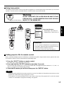
• When your PC is attached to the projector for the first time, the “new hardware wizard” will launch automatically.
When USB cable connects for the first time between projector and PC, the following massage appear from PC. The
reason that the driver not installed, therfore press “NEXT” button continuously and finally. Press “Finish”.
The following is in the case of Windows
Using the remote control as a PC mouse
You can use the remote control as your PC mouse. Set the Mode (Projector/Computer) switch on the remote control
to Computer and connect the projector's USB port to your PC counterpart with the accessory USB cable.
Mode switch (Computer/Projector)
Mode switch is set to the Computer position.
• Page button
: Functions as the Page Up button on your PC
keyboard.
: Functions as the Page Down button on your PC
keyboard.
• Arrow ( ) button
These buttons functions as the cursor control buttons
on your PC.
• R-CLICK button
This button functions as the right button on your PC
mouse.
• Click button
This button functions as the left button on your PC
mouse.
REMOTERGB OUT
OUT
WIRED
IN
IN
OUT
OUT
IN
OUT
USB SERIAL
UDIO
RGB 2 IN
> PC < TBMU152
Accessory
USB cable
PC equipped with
a USB port
Projector
Click button
Page button
R-CLICK button
Mode switch
(Computer/Projector)
button
Note
• The optional wireless receiver (Model ET-RMRC1) is needed for a PC not equipped with a USB port. However,
Page buttons do not function.
Using the Remote control unit
• If you click “Cancel”, the “new hardware wizard” launches each time your PC is connected to the projector.
Note

17
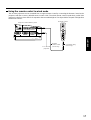
ENGLISH
Projector's side interface panel
To a second
projector
Remote control
Remote
control cable
(accessory)
Conversion plug
(accessory)
REMOTERGB OUT
OUT
WIRED
IN
IN
OUT
OUT
IN
T
USB SERIAL
IO
RGB 2 IN
> PC < TBMU152
Using the remote control in wired mode
Two or more projectors can be controlled from a single Remote Control by connecting the Remote Control to the
projectors with the accessory Wired Remote Control Cable. The wired remote control is particularly useful if the
projector is sited in a place where it is exposed to intense ambient light or if an object blocks the path of IR light from
the Remote Control.

18
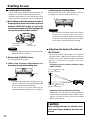
Projection Distances
Installation Geometry
After the projector is roughly positioned, picture size
and vertical picture positioning can be finely adjusted
with the powered zoom lens and lens tilt mechanism.
Setting-up
Projection Schemes
Any of the following four projection schemes can be
used with the PT-L6510E/L6600E projector
depending on user's needs or viewing conditions.
Use “OPTION 1” menu (chosen from the MAIN
MENU) to choose the appropriate projection scheme
(see page 34).
[unit : mm]
L: Projection distance
SH: Image height
SW: Image width
H: Distance from centre of lens to bottom
edge of projected image.
276
H
H
SH
L
L
REMOTERGB OUT
OUT
WIRED
IN
IN
OUTIN
R/R-Y/P
R
G/Y SYNC/HD VDB/B-Y/P
B
IN OUT
OUTIN RL
USB SERIALS-VIDEO IN AUDIO IN
RGB
AUDIO
AUDIO
VIDEO
RGB 2 IN
OUTIN
DVI-D
RGB 1 IN
> PC < TBMU152
346
438
Side view
With optional ceiling mount
bracket (ET-PKL6500)
Screen
Top view
Screen
314
157
175
87.5
L
SW
0.46
0.61
0.76
0.91
1.22
1.52
1.83
2.13
2.44
2.75
3.05
3.35
3.66
3.96
4.27
4.57
0.61
0.81
1.02
1.22
1.63
2.03
2.44
2.84
3.25
3.66
4.06
4.47
4.88
5.28
5.69
6.10
—
1.4
1.8
2.1
2.9
3.6
4.3
5.1
5.8
6.6
7.3
8.1
8.8
9.5
10.3
11.0
0.76
1.02
1.27
1.52
2.03
2.54
3.05
3.56
4.06
4.57
5.08
5.51
6.10
6.60
7.11
7.62
1.4
1.9
2.4
2.9
3.9
4.9
5.9
6.9
7.9
8.9
9.9
10.9
11.9
12.9
13.9
14.9
0.02 to 0.22
0.03 to 0.30
0.04 to 0.38
0.05 to 0.45
0.06 to 0.60
0.08 to 0.76
0.09 to 0.91
0.11 to 1.06
0.12 to 1.21
0.14 to 1.37
0.15 to 1.52
0.17 to 1.67
0.18 to 1.82
0.20 to 1.98
0.21 to 2.13
0.23 to 2.28
Projection distance: L
Unit : m
Height
position: H
Diagonal length
Height (SH) Width (SW) Wide (LW)
Telephoto (LT)
Screen Size (4 : 3)
Table standing
Projection Scheme 2
Ceiling mount
Projection Scheme 1
Front projection
Rear projection
(Default position)
Note
• The dimensions in the table above and the values
obtained from the above formulas may contain
slight errors.
• It is recommended that you use the projection
distance for the wide lens position (except in cases
where the diagonal picture size is 0.762 m).
• The above dimensions are the case when the
aspect ratio is 4:3. When an SXGA signal is input
and projected, the right and left ends of the picture
will be blanked the aspect ratio will be 5:4.
Setting-up dimensions which are not given in the above
table can be calculated using the formulas below.
If the screen size (diagonal) is SD, then the following
formulas is first used to obtain the screen width (SW).
SW = (SD x 0.0254) x 4 ÷ 5 (SD unit is inches)
The value for SW obtained above can then be used
with the following function to calculate the projection
distance for the wide lens position (LW) and the
projection distance for the telephoto lens position (LT).
LW = 1.831 x SW - 0.071
LT = 2.449 x SW - 0.066
For 16 : 9 aspect rations, the following formal can be
used to calculate the screen width (SW).
SW = (SD x 0.0254) x 16 ÷ 327

19
ENGLISH
Setup precautions
• Before connecting any of your video/audio equipment to the projector, carefully read the owners manual supplied
with the equipment once again.
• All cable connections should be made with the entire system devices, including the projector, first turned off.
• Obtain commercial interconnecting cables for devices supplied with no accessory or optional interconnect cables.
• Video signals containing too much jitter may cause the images on the screen to randomly wobble or shake. Inserting
a time base corrector (TBC) in the projector's video line will relieve this problem.
• The projector only accepts composite-video, S-video, analogue-RGB (with TTL sync. level), and digital signal from
PC.
• The projector contains built-in speakers. When greater sound output is required, use an audio amplifier connected
to the projector's AUDIO OUT jack. Once the cable is plugged into the AUDIO OUT jack, the audio signal lines to the
internal speakers are automatically cut off.
• Some PC models are not compatible with the PT-L6510E/L6600E projector.
• The pin assignments on the S-VIDEO IN port are as
follows:
• The pin assignments on the DVI-D input port are as
follows (interface with TMDS port on PC):
• The pin assignments on the RGB2 input port are as
follows:
Pin : Not used.
Pins - , , and : Ground.
Pins and : Valid if the PC has the corresponding function.
Viewed from mating side
Viewed from mating side
Viewed from mating side
Pin No.
Signal
Ground (luminance)
Ground (colour)
Luminance signal
Colour signal
Signal
R/P
R
G/G · SYNC/Y
P
B
SDA
HD/SYNC
VD
SCL
Pin No.
Pin No
.
Signal
T. M. D. S data 2-
T. M. D. S data 2+
T. M. D. S data 2/4
shield
T. M. D. S data 4-
T. M. D. S data 4+
DDC clock
DDC data
T. M. D. S data 1-
T. M. D. S data 1+
T. M. D. S data 1/3
shield
T. M. D. S data 3-
Signal
T. M. D. S data 3+
+5 V
Ground
Hot plug sense
T. M. D. S data 0-
T. M. D. S data 0+
T. M. D. S data 0/5
shield
T. M. D. S data 5-
T. M. D. S data 5+
T. M. D. S clock
shield
T. M. D. S clock+
T. M. D. S clock-
Pin No.

20
REMOTERGB OUT
OUT
WIRED
IN
IN
OUTIN
R/R-Y/P
R
G/Y SYNC/HD VDB/B-Y/P
B
IN OUT
OUTIN RL
USB SERIALS-VIDEO IN AUDIO IN
RGB
AUDIO
AUDIO
VIDEO
RGB 2 IN
OUTIN
DVI-D
RGB 1 IN
> PC < TBMU152
OUT
Laser disc player
Video deck
Di
g
ital Hi-vision video deck
Audio equipment
Control PC
Colour monitor
Red (Conect P
R
)
Blue (Conect P
B
)
Green(Conect Y)
Example of connecting with AV products
Note
• Only a single pair of audio inputs (AUDIO IN L-R) is available for the composite and S video, also only a signal
RGB audio input is available for the RGB1, RGB2 and DVI-D. You will need to change audio input connections
depending on your signal selection.
• If your audio equipment is connected to the projector's AUDIO OUT jack, the remote control supplied with the
projector can be used to control volume, balance, and mute on the audio output line.
Setting-up
Page is loading ...
Page is loading ...
Page is loading ...
Page is loading ...
Page is loading ...
Page is loading ...
Page is loading ...
Page is loading ...
Page is loading ...
Page is loading ...
Page is loading ...
Page is loading ...
Page is loading ...
Page is loading ...
Page is loading ...
Page is loading ...
Page is loading ...
Page is loading ...
Page is loading ...
Page is loading ...
Page is loading ...
Page is loading ...
Page is loading ...
Page is loading ...
Page is loading ...
Page is loading ...
Page is loading ...
Page is loading ...
Page is loading ...
Page is loading ...
-
 1
1
-
 2
2
-
 3
3
-
 4
4
-
 5
5
-
 6
6
-
 7
7
-
 8
8
-
 9
9
-
 10
10
-
 11
11
-
 12
12
-
 13
13
-
 14
14
-
 15
15
-
 16
16
-
 17
17
-
 18
18
-
 19
19
-
 20
20
-
 21
21
-
 22
22
-
 23
23
-
 24
24
-
 25
25
-
 26
26
-
 27
27
-
 28
28
-
 29
29
-
 30
30
-
 31
31
-
 32
32
-
 33
33
-
 34
34
-
 35
35
-
 36
36
-
 37
37
-
 38
38
-
 39
39
-
 40
40
-
 41
41
-
 42
42
-
 43
43
-
 44
44
-
 45
45
-
 46
46
-
 47
47
-
 48
48
-
 49
49
-
 50
50


Panasonic PTL6510E User manual
- Category
- Data projectors
- Type
- User manual
Ask a question and I''ll find the answer in the document
Finding information in a document is now easier with AI
Related papers
-
Panasonic PT-RZ14KU User manual
-
Panasonic PT-D10000U User manual
-
Panasonic PTDW5100EL User manual
-
-
-
-
-
Panasonic PT-AE2000U User manual
-
-
Other documents
-
Polaroid PV 360 User manual
-
Sanyo PLC-XF60A User manual
-
 BOXLIGHT CPX960WA User manual
-
Mitsubishi XL2U User manual
-
 Mitsubishi Electronics S290U User manual
-
Hitachi CPX960WA User manual
-
-
Liesegang dv475 User manual
-
Hitachi CPX935 User manual
-

