Eaton Powerware SPD120i/A Installation guide
- Category
- Surge protectors
- Type
- Installation guide

Specification are subject to change without notice. Copyright 2005 Eaton Power Quality Pty Ltd
Technical Specification –SPD120i/A
Tvss Doc# 510077
Page 1 of 2
Web: http://www.powerware.com.au
Phone: 1300 UPS UPS
SPD120i/A SURGE DIVERTER
(Single mode, 220-277V (380-480V), 100kA)
INSTALLATION INSTRUCTIONS
FEATURES
• 1 mode protection (L-N or L-E)
• Compact solution for primary protection
• DIN43880 case, 35 mm DIN-rail mountable
• All MOVs thermally protected
• Includes dry-contact alarm
Applications
• Mains point-of-entry /Main SWB
• Telecommunication Systems / Rectifiers
• Process and Control Systems / Factories & Units
• Computer Systems / Medical Systems
• All sensitive Electronic Equipment
FUNCTIONAL DESCRIPTION
The SPD120i is designed to protect single and 3-
phase power systems against damage from surges
and spikes caused by lightning and other electrical
sources. The unit is intended for point-of-entry or
main-board protection and is connected in parallel
with the power system via HRC fuses. This unit is
available in various models for different voltages and
applications. Check that the model you have
purchased is rated correctly for your power system.
.
This model (SPD120i/A) is designed for single
and 3-phase power systems, with a grounded
neutral, in the range of 220-277V(380-480V). If
your power system is “delta” (i.e. ungrounded),
or of a different voltage, this model is NOT
suitable.
Please contact your supplier for a suitable model to
suit your application.
OPERATION
Two lamps on the front panel indicate the operation
status of the unit. The ‘OK’ lamp indicates that power
is applied to the unit and the ‘FAULT’ lamp indicates
reduced protection. If the ‘FAULT’ lamp is lit it is likely
that the unit is damaged and must be replaced. If the
breaker/fuse is intact and power is definitely being
supplied through the unit (check with meter) but the
‘OK’ lamp doesn’t light then the unit is faulty and
must be replaced.
WARRANTY
Eaton Power Quality warrants this unit against faulty
parts and workmanship for a period of 12 months
from the date of purchase. If this product fails to
operate correctly, please contact your Eaton
representative. This warranty doesn’t cover neglect
or intentional misuse. As this product is intended for
use in electrically harsh environments no claim is
made of suitability for purpose. This unit is designed
to reduce the likelihood of damage, not prevent it.
Please also note that an excessive surge, such as
from a direct lightning strike to the site or a power
system fault, may cause damage to the unit and
render it inoperable. A unit that has been damaged in
this way is not warrantable.
For installation details,
see over page.
SPECIFICATIONS
Manufacturers name and model Eaton Powerware
SPD120i/A
Method of mounting Fixed. DIN Rail mount
Input voltage 220-277VAC (380-480V)
40-70Hz
Maximum continuous operating
voltage - MCOV
320VAC
Temporary over-voltage – TOV 350VAC, 15 mins
Service type TN-C and TN C-S (3-phase
with grounded neutral)
Test classification Class II
Supply current 50mA
Initial clamp voltage 560V
Maximum rated surge current -
Ismax 8/20us
100kA
Nominal surge current - In
8/20us
50kA
Residual voltage (Vpl) @
3kA, 8/20uS
1.0kV
Residual voltage (Vpl) @
40kA, 8/20uS
1.65kV
Residual voltage (Vpl) @ Ismax
100kA, 8/20uS
2.5KV
Energy absorbtion (2ms) 2130j
Nominal surge lifetime (In) 50kA (8/20uS), 20 times
Internal protection (fusing)
MOV thermal fuses 135°C
External disconnector
requirements
Gg/Gl HRC fuses, 1 per
phase, 125A maximum.
Terminations Power terminals 16mm
2
,
Alarm terminals 1.5mm
2
Alarms/indicators 5 indicators, dry contact
alarm relay –
250VAC/32VDC, 5A
Location Category Indoor
Enclosure rating IP20
Applicable standards. IEC61643-1, IEC610006,
ANSI/IEEE C62.41,
AS1768-2003, AS3100
Dimensions DIN43880, 4 units (70mm)
Weight 200g
Environment -10 to 60C, 0-90%RH
Warranty 12 months, workmanship
and materials

Specification are subject to change without notice. Copyright 2005 Eaton Power Quality Pty Ltd
Technical Specification –SPD120i/A
Tvss Doc# 510077
Page 2 of 2
Web: http://www.powerware.com.au
Phone: 1300 UPS UPS
INSTALLATION
Refer to the procedure and diagram shown to connect the
SPD120i/A.
PROCEDURE:
1. CHECK
• Always work safely – disconnect power before making
connections.
• All wiring must be carried out by suitably qualified
personnel according to the applicable standards.
• Check for correct operating voltage and power system.
This model (SPD120i/A) is designed for power systems
in the range of 220-277V(380-480V). If your power
system is “delta” (i.e. ungrounded), or of a different
voltage, this model is not suitable. Please contact
your supplier.
• ** For installation adjacent to an M.E.N. link, use the L-N
mode. Insert insulated link as shown.
• ** For installations remote from the M.E.N., use the L-E
mode. Remove link. A separate N-E protector is required
Contact your distributor for information.
• Always use the correct size HRC fuses.
• For services >125A, use 125A fuses. For services
<125A, use one step below service fuses (i.e. 80A
service =63A fuses). DO NOT USE AN MCB.
• Always use Gg or Gl-rated fuses. Do not use delay types
or ‘semiconductor’ fuses.
• Consider fitting a fuse-switch or a separate isolation
switch to facilitate safe maintenance in the future.
2. INSTALL
• Locate a fuse position as close as possible to the Main
Switch.
• Install fuseholders or fuse-switch.
• Locate a suitable position for the SPD, ensuring
adequate space for cables. Do not install above heat-
generating objects or in any position that is exposed to
weather.
• Install unit to DIN-rail in switchboard or cabinet.
3. CONNECT
• Connect wiring - refer to connection diagrams. If using
stranded cable, always use wire ferrules for lowest
resistance and to prevent damage to the wire.
• Use a suitably-rated cable for power connections. Cable
should be rated for operation at the system voltage and
should be 4mm
2
to 16mm
2
.
• Use short cables for phase, neutral and earth
connections or protection will be reduced.
•
Use a suitably-rated cable for alarm connections. Cable
should be rated for operation at the system voltage and
should be 0.5mm
2
to 1.5mm
2
.
4. NOTES:
• 125A fuses are rated such for maximum surge rating.
On services below125A, use the correspondingly lower
sized fuse (i.e.80A service = 63A fuse).
•
Wiring from fuse to SPD is carrying surge currents only,
not load current. This means that smaller cables may be
used than is normal for the current rating.
•
If using under-sized cables, some energy authorities
require double insulation (i.e. sleeving) of the cables.
•
Maximum alarm relay resistive load is 5A.
•
It is recommended not to connect the alarm contacts to
AC mains circuits if possible, to prevent flashover from
surges on the AC line. Connect to a PLC or BMS if
available.
•
Do not Megger test cabling with unit connected – unit
may be damaged.
EARTHING
For proper operation, all surge diverters rely upon a good earth
connection:
• The main earth wire (from earth link on switchboard to ground
rod or system) MUST be at least 6mm diameter (preferably
larger) and should be as short as possible.
• Earth connections from the unit to neutral or earth link MUST
be as short as possible.
Failure to consider the above points can result in improper
operation of the unit and possible damage to the installation.
L-E mode
connections:
L-N mode
connections:
-
 1
1
-
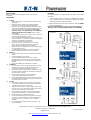 2
2


Eaton Powerware SPD120i/A Installation guide
- Category
- Surge protectors
- Type
- Installation guide
Ask a question and I''ll find the answer in the document
Finding information in a document is now easier with AI
Related papers
-
Eaton Powerware SPDT60-255 User manual
-
-
-
-
-
-
Sharp CVX100 User manual
-
-
-
Other documents
-
Philips SMARTSPOT User manual
-
-
-
-
 EATON BUSSMANN CC06FA500MA-TR Operating instructions
-
EFI Titan 100WF Instruction Bulletin
-
Hager JKD201SPD Surge Protection Kit User manual
-
Hager JKD202SPD User manual
-
 BG Electrical CUSPDT21-B Type 2 Single Phase Surge Arrester Main Switch User manual
-
Square D QO250PSPD Operating instructions

