Page is loading ...

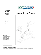
SB700 INDOOR CYCLE OWNER’S MANUAL
Model : 168683700
Model : 168683700Model : 168683700
Model : 168683700
OWNERÊS MANUAL
OWNERÊS MANUALOWNERÊS MANUAL
OWNERÊS MANUAL
PLEASE CAREFULLY READ THIS ENTIRE MANUAL BEFORE OPERATING
YOUR NEW INDOOR CYCLE

Dyaco Canada Inc 2013
2
TABLE OF CONTENTS
Product Registration 3
Important Safety Instructions 4
Important Operation Instructions 5
Assembly Instructions 6
Operation of Your New Indoor Cycle 12
Exploded View Diagram 18
Parts List 19
Manufacturer’s Limited Warranty 21
ATTENTION
THIS INDOOR CYCLE IS INTENDED FOR RESIDENTIAL USE ONLY AND IS
WARRANTED FOR THE APPLICATION. ANY OTHER APPLICATION VOIDS THIS
WARRANTY IN ITS ENTIRETY.

Dyaco Canada Inc 2013
3
CONGRATULATIONS ON YOUR NEW INDOOR CYCLE TRAINOR AND WELCOME TO
THE SOLE FAMILY!
Thank you for your purchase of this quality Sole indoor cycle from Dyaco Canada Inc. Your
new indoor cycle has been manufactured by one of the leading fitness manufacturers in the
world and is backed by one of the most comprehensive warranties available. Dyaco
Canada Inc. will do all we can to make your ownership experience as pleasant as possible
for many years to come.
If you have any questions about your new Sole product or questions about the warranty
contact Dyaco Canada Inc. at 1-888-707-1880.
Please take a moment at this time to record below the name of the dealer, their telephone
number, and the date of purchase for easy contact in the future. We appreciate your
confidence in SOLE and we will always remember that you are the reason that we are in
business. Please complete and mail your registration card today and enjoy your new indoor
cycle trainor.
Yours in Health,
Dyaco Canada Inc.
Name of Dealer
Telephone Number of Dealer
Purchase Date
PRODUCT REGISTRATION
RECORD YOUR SERIAL NUMBER
Please record the Serial Number of this fitness product in
the space provided below.
Serial Number

Dyaco Canada Inc 2013
4
IMPORTANT SAFETY INSTRUCTIONS
WARNING - Read all instructions before using this appliance.
1. Use this equipment only for its intended use as described in this manual. Do not
attempt to ride this bike at high pedal speeds until you have ridden the bike for some
time and are comfortable riding at slower pedal speeds.
2. The bike is NOT equipped with a freewheel system which means that when the
flywheel is in motion, the pedals will be in motion. Do not attempt to stop the unit by
applying backward pressure to pedals while they are turning as knee injury may
occur. Do not attempt to remove your feet from pedals while they are moving.
3. Wait for flywheel to coast to a stop before dismounting the bike. If you want to stop
the flywheel, push down on the brake knob.
4. Serious injury or death may occur from over-training. Consult a medical doctor or
qualified fitness instructor to determine an exercise program appropriate for your
level of fitness.
5. Do not attempt to turn the pedal cranks by hand. Do not touch any driving
mechanism while it is in motion as possible injury could occur.
6. In a home setting, keep children away from the bike when it is not in use. Keep
children and pets away from the unit while it is in use.
7. Do not attempt to perform dip movements on handlebars.
8. Never drop or insert any object into any opening of the bike.
9. Only use the bike on a stable, level floor.
10. Follow instructions for safe use of the equipment including proper seat position,
handlebar position, and use of foot positioning system of pedals. Do not attempt to
pull up handlebar post and seat post over the 'MAX.'graduation.
11. For safe operation, allow for at least 1foot (30cm) of free space to either side of the
unit and 2 feet (60cm) of free space to the rear of the unit.
Regularly examine the bike for damage and wear. Inoperable components should be
replaced immediately or the equipment should not be used until it is repaired.
Failure to follow all guidelines may compromise the effectiveness of the exercise
experience, expose yourself (and possibly others) to injury, and reduce the longevity of the
equipment.
SAVE THESE INSTRUCTIONS - THINK SAFETY!

Dyaco Canada Inc 2013
5
IMPORTANT OPERATION INSTRUCTIONS
WARNING - AS THE OWNER OF THIS EXERCISE EQUIPMENT, YOU SHOULD INSIST
THAT ALL USERS FOLLOW THE SAME GUIDELINES: YOU SHOULD MAKE THIS
MANUAL AVAILABLE TO ALL USERS.
1. Obtain a complete physical examination from your medical doctor and enlist a
health/ fitness professional’s aid in developing an exercise program suitable for your
current health status.
2. When working out for the first time, start out slowly for a minimum of five minutes.
After your muscles are warmed up, gradually increase the pedaling speed and/or
resistance.
3. The speed and duration of your exercise program should always be subject to how
you feel. Never permit peer pressure to exceed your personal judgment while
exercising.
4. Overweight or severely de-conditioned individuals should be particularly cautious
when using the equipment for the first time. Even though such individuals may not
have histories of serious physical problems, they may perceive the exercise to be far
less intense than it really is, resulting in the possibility of overexertion or injury.
5. Proper installation and regular maintenance are required to ensure user’s safety.
Maintenance is the sole responsibility of the owner.

Dyaco Canada Inc 2013
6
ASSEMBLY PACK CHECKLIST
1
HARDWARE STEP 1
2
HARDWARE STEP 2
4
HARDWARE STEP 4
ASSEMBLY TOOLS
#82
. 3/8”
Nut (4 pcs)
#81
. 3/8” x 3-1/2”
Button Head Socket Bolt
(4 pcs)
#83
. 3/8” x 23mm
Curved Washer (4 pcs)
#91
. M5 x 10mm
Screw (2 pcs)
#49
. 5/16”
Split Washer (4 pcs)
#48
. 5/16” x 16mm
Flat Washer (4 pcs)
#88
. 5/16” x 5/8”
Screw (4 pcs)
#85. Wrench
#86
. Combination M5 Allen Wrench &
Phillips Head Screw Driver

Dyaco Canada Inc 2013
7
ASSEMBLY INSTRUCTIONS
PRE-ASSEMBLY
1. Using a razor knife (Box Cutter) cut the outside, bottom, edge of box. Lift Box
over the unit and unpack.
2. Carefully remove all parts from carton and inspect for any damage or missing
parts. If damaged parts are found, or parts are missing, contact your dealer
immediately.
3. Locate the hardware package. Remove the tools first. Remove the hardware for
each step as needed to avoid confusion.
1
STABILIZER TUBES
HARDWARE STEP 1
1. Attach the Front ( the one with the wheels mounted in the
bottom of the tube) & Rear floor stabilizer tubes by inserting two
Carriage Bolt (81) through each tube. Fasten two Curved
Washers (83) and two Nuts (82) on each tube using the wrench
(85) provided.
#82
. 3/8” Nut (4 pcs)
#81. 3/8” x 3-1/2”
Carriage Bolt (4 pcs)
#83. 3/8” x 23mm
Curved Washer (4 pcs)

Dyaco Canada Inc 2013
8
2
REAR STABILIZER COVER
HARDWARE STEP 2
1. Attach the Rear Stabilizer cover with two Screws (91). Tighten
using the Combination M5 Allen Wrench & Phillips Head Screw
Driver (86).
3
CONSOLE
#91
. M5 x 10mm
Screw (2 pcs)

Dyaco Canada Inc 2013
9
Sole Indoor Cycling Console Battery Installation:
1. Remove the battery cover from the back of the computer.
2. Insert 2 AAA batteries into the battery compartment and reinstall the battery cover.
3. When Battery working voltage is too low, The “Low battery” indicator will show up on
the console display indicating it is time to change the batteries.
Speed Sensor Transmitter Battery Installation
1. Remove the battery cover from the transmitter.
2. Install 2 AAA batteries in the battery compartment and reinstall the battery cover.
3. When new batteries are installed in the transmitter or console you must perform the
synchronizing procedure below for the console to work properly
Synchronizing the transmitter to the console:
After installing the batteries, and before attaching the console and transmitter to the bike,
you must synchronize the two so they can ‘talk’ to each other.
1. Press and hold the two keys on the front of the console for about 3 seconds until the
display shows ID - -
2. Now press and hold the blue button on the transmitter for 3 seconds and release. The
console display should show ID 0. NOTE: You must press the blue button within 10
seconds after the console is showing ID - - otherwise the console will show: ID ER. If
the console shows this error then restart the procedure again.
3. It may be necessary to remove and re-install the batteries in both the console and
transmitter if you continue to receive an error.
Console Installation:
1. Install the mounting clamp (2) to the back of the console (1) with the clamp mounting
screw (3).
2. Install and slightly tighten the thumb screw (4) then adjust the console angle for
optimal visibility. Once the console is adjusted, continue to tighten the screw until it is
securely attached to the handle bar.
Transmitter Installation:
Make sure to route the speed sensor wire behind the frame member. Plug the sensor
wire into the transmitter as shown below
Install the transmitter, at the angle shown below, onto the pre-installed Velcro strip
located on the back of the chain cover. Make sure the sensor wire connection is at the
top left when mounting the transmitter.
Make sure the sensor wire is routed away from the spinning flywheel

Dyaco Canada Inc 2013
10
4
HANDLEBAR
HARDWARE STEP 4
1. Attach the handlebars (make sure they are oriented as in the
illustration) with four Screws (88), four Split Washers (49), and
four Flat Washers (48). Tighten firmly using the Combination
M5 Allen Wrench & Phillips Head Screw Driver (86).
#49
. 5/16” Split Washer
(4 pcs)
#48. 5/16” x 16mm Flat
Washer (4 pcs)
#88. 5/16” x 5/8” Screw
(4 pcs)

Dyaco Canada Inc 2013
11
5
LEFT/RIGHT PEDALS
1. Attach the Right and Left pedals to the appropriate crank. The
pedals have an “R” and an “L” stamped on the end of the threaded
area to distinguish them. Check the illustrations to make sure you
are attaching each to the correct side. Note: the left side has left
hand threads; therefore you will screw it on in a counterclockwise
direction. Tighten each pedal as firmly as possible with the Wrench
(85) provided. If you here a thumping sound when you are pedaling,
this usually means one or both pedals are loose. You may need to
retighten them after use.

Dyaco Canada Inc 2013
12
OPERATION OF YOUR INDOOR CYCLE
GETTING FAMILIAR WITH THE CONTROL PANEL
CONSOLE
PLEASE NOTE:
1. The Sole Indoor Cycling Console system is designed as a sealed unit and not
meant to be opened other than for the sole purpose of installing batteries. Any
opened units will void the warranty.
2. To clean the Sole Indoor Cycling Console use a clean damp cloth. Use of any
caustic cleaning solutions will void the warranty.
3. The Sole Indoor Cycling Console system is NOT waterproof, only water resistant.
Any excessive exposure to water will void the warranty.
The Sole Indoor Cycling Console carton consists of a computer console and a speed
sensor transmitter.
The transmitter counts the number of times the magnet, which is mounted on the crank
assembly, passes the sensor. The speed sensor transmitter will then send a coded signal
to the console which contains the measured value (Speed and Cadence ).

Dyaco Canada Inc 2013
13
CONSOLE OPERATION
TIME
Time is measured in min:sec. There is a time of day clock and a workout timer clock. The
workout time will count up or count down during pedaling. If pedaling stops, the time will
stop counting after 3sec.
RPM/CADENCE
Cadence is the measurement of how fast the cranks are rotating in RPM. The approximate
speed of the bike can also be displayed in MPH or KPH. In addition to MPH/KPH, the RPM
section of the display also has a bar graph that allows the rider to visually keep track of the
approximate RPM.
DISTANCE
Distance is the measurement of the virtual distance traveled on the bike. This distance is
based on the user riding a bike with tires that are the same size as the Sole group bike’s
flywheel.
KCAL
Kcal is the approximation of calories burned during your work out. The calories are an
estimate only.
HEART RATE
This is the approximation of heart rate detected from the chest strap (sold separately)
during your work out.
Changing from metric to standard data or vice versa
Note: you will have to press the buttons fairly quickly or the screen will return to the prior
setting.
1. Press the left key repeatedly until workout DISTANCE is displayed
2. Press and hold the right key down until workout TIME is displayed
3. Press the left key 4x
4. Press the right key one time
5. Press the left key one time
6. Press and hold the left key down until the switch is complete
QUICK START
When the console is in Power Saving Mode, hold down any key to wake up the console and
go to the start-up screen, also called “QUICK Start” active state.
POWER SAVING MODE QUICK START MODE

Dyaco Canada Inc 2013
14
MODE SELECT
Press the left hand key to select the SPEED, DIST, TIME or CLOCK at the bottom of the
display.
RESET/HEART RATE ALARM SELECT
1. Press the right hand key to activate the heart rate (this will only
register if you are wearing the chest strap which is sold
separately). If the alarm is on, the alarm icon will flash and a
beep will sound to indicate that your heart rate is either above
or below the selected target zone.
2. To clear exercise TIME, AVG SPEED, AVG PULSE,
DISTANCE, and KCAL, press the left key until TIME is
displayed, then press and hold the right key until data is reset.
HEART RATE TARGET ZONES
1. Press the left hand key until ‘SPEED’ is
displayed, then hold the right hand key for
3 seconds. The TIME will be flashing;
press the left hand key to select the heart
rate target zone settings.
2. Press the right hand key to increase
maximum heart rate limit. After setting the
maximum heart rate, press the left hand
key to adjust the minimum heart rate limit.
HEART RATE TARGET ZONES
1. GENDER: Press the left hand key until SPEED is displayed, then press the right hand
key for 3 seconds. The TIME will be flashing, press the left hand key until the gender
icon is blinking. Press the right hand key to select gender.
2. Press the left hand key to set the measuring value for weight (Lb or Kg); press the
right hand key to select.
3. BODYWEIGHT: Press the left hand key to set the bodyweight. Press the right hand
key to increase the weight. Press and hold the right hand key for rapid advance.

Dyaco Canada Inc 2013
15
FIRST TIME USER INSTRUCTIONS
ADJUSTING THE BIKE FOR A PROPER FIT
Take some time to learn how to properly adjust the bike to your body; it will make your
workouts more pleasant and a safer experience too. Riding the bike when it is incorrectly
adjusted can result in discomfort and increase your risk of injury.
ADJUSTMENT OF SEAT POSITION
Seat Height Adjustment
1. Standing next to the bike, adjust the seat until it is about hip height.
2. Rotate the crank arms until the pedals are in the vertical position: 12
and 6 o’clock.
3. Place your foot in the toe cage of the pedal closest to the floor and
mount the bike.
Ensure that the ball of your foot is over the center of the pedal. Your
leg should be slightly bent at the knee, about 5 degrees.
4. If your leg is too straight or your foot cannot touch the pedal you will
need to lower the seat height. If your leg is bent too much, you will need to raise the
seat height.
5. Dismount the bike. Then loosen the quick release lever on the seat post and adjust up
or down as necessary.
6. When the seat is in the desired position, tighten the quick release to secure the seat
post.
7. Note the final position mark on the seat post for future reference.
Seat Forward/Aft Adjustment
8. Sit on the bike with the crank arms in the 3 and 9 o’clock positions. A
proper forward/aft position (for road bike training) of the seat is
achieved when the small bump at the top of your shin is above the
pedal axle.
9. Dismount the bike. Loosen the quick release under the seat and slide
the seat forward or backward as desired; tighten the quick release
lever.
HANDLE BAR ADJUSTMENT
Handlebar Height Adjustment
1. The handlebar height is a matter of preference. Start with a handlebar
height that is the same as the seat’s height. Adjusting the handlebar
higher will give the rider a more upright position; lower will result in a
more crouched position.
2. Raise or lower the handlebar by loosening the quick release on the
handlebar post and adjust by sliding the handlebar mount up or down
as desired. Then tighten the quick release to secure the handlebar
post. Note the final position mark on the handlebar post for future
reference.
Adjustment of Handlebar’s Forward/Aft Position
3. Loosen the quick release under the handlebar and slide the
handlebar forward or backward as desired. A suitable forward/aft
position should allow the rider to comfortably grasp the handlebar with a
slight bend at the elbow.
4. Tighten the quick release to secure the handlebar assembly.

Dyaco Canada Inc 2013
16
DUAL FUNCTION PEDAL
ADJUSTING THE PEDAL STRAPS
Place your feet in between the aluminum surface of the pedal and the nylon foot strap that
wraps around it. If the opening is too narrow, depress the spring loaded clasp with one
hand and pull on the nylon strap with the other to increase the opening area. If it is too
loose or to tighten the strap, depress the spring loaded clasp, then pull on the open end of
the nylon strap until the strap is snug around each foot.
BASIC OPERATION
Now that you have established a proper riding position, take a few minutes to ride the bike
and determine that your position is comfortable. Start pedaling at a slow pace with your
toes and knees pointed directly forward. Hold the handlebar lightly and in a position that
allows your shoulders and upper body to relax. Pedal easily, at a low resistance until you
feel confident that you could ride in that position for the duration of your workout.
WARNING!
IF AT ANY TIME DURING YOUR WORKOUT, YOU FEEL CHEST PAIN, EXPERIENCE
SEVERE MUSCULAR DISCOMFORT, FEEL FAINT, OR ARE SHORT OF BREATH,
STOP EXERCISING AT ONCE. IF THE CONDITION PERSISTS, YOU SHOULD
CONSULT YOUR MEDICAL DOCTOR IMMEDIATELY.
1. Pedaling resistance is controlled by the tension knob. Resistance can be changed at
any time by turning tension knob: clock-wise for more resistance; counterclockwise for
less resistance.
2. To apply the brake, press down on the tension knob.
3. Before dismounting, apply the brake to stop flywheel, or increase resistance and let
flywheel come to a stop.

Dyaco Canada Inc 2013
17
TROUBLESHOOTING
No Display on Console
1. Hold down any key to bring the console to “Quick Start” mode.
2. Ensure that the batteries are installed properly in the console and transmitter. If they
are, install fresh batteries.
No Heart Rate signal displayed (chest strap transmitter sold separately)
1. Ensure that your chest strap is worn correctly and that there is moisture under the
electrodes.
2. Relocate the bike away from any equipment that could potentially interrupt the radio
frequency signal, such as a DVD player or television, etc.
Cadence number jumps high or low
1. Separate bikes that may be set to the same console code and are cross-talking, or
re-synchronize the transmitter and console (see page 9).
2. Relocate the bike to a different part of the room, away from any RF interference areas.
Heart Rate signal gets interrupted or drops out (chest strap transmitter sold
separately)
1. Ensure that there is a minimum distance of 36 inches between bikes.
2. Verify that your chest strap is secure and that the electrodes are making contact with
your chest at all times.
CAUTION!!
EXTERNAL INTERFERENCE MAY BE CAUSED BY OTHER ELECTRONIC DEVICES,
SUCH AS: NEARBY TELEVISIONS, STEREO EQUIPMENT, SPEAKERS, ELECTRICAL
WIRE CABLING, ETC. IF YOU EXPERIENCE DISTURBANCES IN THE CONSOLE
DISPLAY TRY MOVING YOUR BIKE(S) AWAY FROM POTENTIAL RF INTERFERENCE
AREAS.
MAINTENANCE GUIDELINES
MAINTENANCE SCHEDULE
PART RECOMMENDED ACTION FREQUENCY CLEANER
LUBRICANT
Pedals Ensure that pedals are tight in
crank arms; that all screws on
pedals are tight; and that the
pedal straps are not frayed
Before each use
N/A N/A
Frame Wipe down by using a soft
damp clean cloth
Daily Water N/A
Flywheel Wipe down by spraying on a
rag and applying a light coat
to sides of the flywheel
Weekly WD-40
spray.
N/A
Brake Pad
Inspect for excessive wear or
a dry leather brake pad
Weekly N/A 3-IN-ONE Oil or
10W oil. Do not
use
silicone-based
lubricants
1. Do not service internal parts of pedals. If they are found to be worn internally, we
recommend replacing the pedal.
2. Use of lubricants or cleaning solutions other than those so specified will result in
diminished performance and a shorter life span for that part.


Dyaco Canada Inc 2013
19
PARTS LIST
KEY NO.
PART NO.
Description
Q
’
TY
1
683700
01
Main Frame
1
2
683700
02
Front Stabilizer
1
3
683700
03
Rear Stabilizer
1
4
683700
04
Handlebar Post
1
5
683700
05
Seat Post
1
6
683700
06
Handlebar
1
7
683700
07
Sliding Seat Mount
1
8
683700
08
Sliding Handlebar Mount
1
9
683700
09
Brake Pad Bracket
1
10
683700
10
Brake Pad
-
Wool Felt
1
11
683700
11
Bushing
1
12
683700
12
N
ut
1
14
683700
14
Spring
2
15
683700
15
M10 × P1.25 × 3T_Luck Nut
2
16
683700
16
Brake Tension Knob
1
18
683700
18
M6 × 15mm_Phillips Head Screw
4
19
683700
19
8 × 40m/m_Quick Release lever
2
20
683700
20
8 × 25m/m_Quick Release Lever
2
21
683700
21
Alumi
num Locking V
-
Blocks
4
22
683700
22
5/16" × 35 × 3.0T_Flat Washer
1
25
683700
25
Pedal Set
(
25L.25R
)
1
26
683700
26
Anti
-
Rotation Washer
1
27
683700
27
Seat
1
29
683700
29
5 × 16m/m_Tapping Screw
2
30
683700
30
3.5 × 12m/m_Sheet Metal Screw
3
31
683700
31
Flywheel
1
32
683700
32
Bearing Housing
2
33
683700
33
Flywheel Axle
1
34
683700
34
Woodruff Key
1
35
683700
35
Flywheel Pulley
1
36
683700
36
5/16" × 3/4"_Button Head Socket Bolt
1
37
683700
37
5/16" × 20 × 3.0T_Flat Washer
1
38
683700
38
5/16" × 3/4"_
Button Head Socket Bolt
6
39
683700
39
M6 × 10L_Flat Phillips Head Screw
6
40
683700
40
Belt
1
41
683700
41
Drive Pulley
1
42
683700
42
Crank Arm
(
L
)
1
43
683700
43
Crank Arm
(
R
)
1
44
683700
44
Crank Arm Dust Cap
2
45
683700
45
Crank Axle
1
46
683700
46
5/16" × 1/2"_Button Head Socket Bolt
5
48
683700
48
5/16" × 16 × 1T_Flat Washer
4
49
683700
49
5/16" × 1.5T_Split Washer
4
50
683700
50
Transportatio
n Wheel
2
53
683700
53
Rubber Foot
4
54
683700
54
3/8"_Nut
4
55
683700
55
Stabilizer End Cap
4

Dyaco Canada Inc 2013
20
KEY NO.
PART NO.
Description
Q
’
TY
56
683700
56
End Cap, Eye Tube
2
57
683700
57
Plastic Slide Insert, Eye Tube
2
58
683700
58
Bottom End Cap, Eye Tube
2
59
6
83700
59
Rear Stabilizer Cover
1
60
683700
60
Chain Cover
(
Outer
)
1
61
683700
61
Chain Cover
(
Inner
)
1
62
683700
62
Flywheel Fender
1
63
683700
63
Pulley Cover
1
64
683700
64
6004_Bearing (NSK)
2
65
683700
65
6203_Bearing
2
66
683700
66
6004_Bearing (TMT)
2
67
683700
67
Ø17_C Ring
1
68
683700
68
Ø20_C Ring
3
69
6
83700
69
1/4" × 3"_Hex Head Bolt
1
70
683700
70
1/4"_Hex Head Bolt
1
71
683700
71
1/4" × 5.5T_Nyloc Nut
1
72
683700
72
3/8" × 2"_Flat Head Socket Bolt
2
73
683700
73
25.5 × Ø16_Star Washer
1
74
683700
74
Idler Axle
1
75
683700
75
Idler Adjustment Carriage B
olt
1
76
683700
76
Console Assembly
1
77
683700
77
Foam Stop, Handlebar Eye Tube
1
78
683700
78
Ø5/16" × 23 × 2.0T_Flat Washer
1
79
683700
79
3/8" × 19 × 1.5T_Flat Washer
2
80
683700
80
M10 × P1.25_Nut
2
81
683700
81
3/8" × 3
-
1/2"_Carriage Bolt
4
82
68
3700
82
3/8"_Cap Nut
4
83
683700
83
3/8" × 23 × 1.5T_Curved Washer
4
84
683700
84
M5 × 12m/m_Tapping Screw
2
85
683700
85
14/15m/m_Wrench
1
86
683700
86
M5_Combination M5 Allen Wrench & Phillips Head Screw
1
87
683700
87
Drink Bottle(Optional)
1
88
683700
88
5/16" × 5/8"_Button Head Socket Bolt
4
89
683700
89
M5 × 10m/m_Socket Head Cap Screw
2
90
683700
90
Ø5 × 10m/m_Tapping Screw
4
91
683700
91
M5 × 10m/m_Phillips Head Screw
2
92
683700
92
M5_Speed Nut Clip
2
93
683700
93
M5 × 10m/m_Tapping Screw
7
94
683700
94
Spring
1
96
683700
96
Safety Sleeve
1
97
683700
97
5/16" × 1"_Button Head Socket Bolt
1
98
683700
98
Sleeve Bushing
1
99
683700
99
3/8" × 3/4"_Button Head Socket Bolt
2
100
683700
100
3/8" × 21 × 2T_Flat Washer
2
/