

2
professional
the
the
the

3
--
5 (page12)
--
Quiet Design -- does
the sound of the compressor starting
R
many
minutes seconds minutes
seconds random
to help avoid power surges
R F P -- This protection feature will a ensure indoor
emperature does not fall below freezing When your PTAC (which is
can be switched off (please see page
9)
feature off (see section
U
room temperature rises
Fan C for ation of The u
application by
electric the
run after the to
Fan Motors-Permanently Lubricated -- The unit have two fan motors for quiet operation and
maximum operating efficiency. Motors are permanently lubricated to reduce maintenance and totally
enclosed to keep dirt and water out of the motor windings.
Outdoor Fan -- The unit automatically selects the most efficient speed for the outdoor fan. The
operating sound level is lower when the outdoor fan can operate in low speed yet there are situations
where it must operate in high speed. The unit changes the fan speed automatically.
Indoor Fan Speed Selections-HIGH/LOW -- The unit automatically selects the most efficient speed
for the outdoor fan. The operating sound level is lower when the outdoor fan can operate in low speed yet
there are situations where it must operate in high speed. The unit changes the fan speed automatically.
y
Total Corrosion© Protection -- All Frigidaire PTAC’s come standard with
anti-corrosion protection, to increase system and component durability in
standard applications and protect system and components in Coastal areas
where Air sea salt content is higher than standard applications. All coils are
treated with a dual hydrophilic coating, and an added hydrophilic coating for all
connecting plates. Standard materials have been replaced with stainless steel
for critical components such as hardware, condenser side panel, compressor
hardware and Condenser fan hardware. Special anti-corrosion paint is used on
the drain pan to ensure the integrity of unit mounts to the chassis.
Dry Mode -- For increased comfort and humidity management, an added “Dry Mode” is standard on all Frigidaire
PTAC’s. This mode feature will help manage and reduce the humidity content within the living space, making it more
comfortable. In DRY mode, the unit will modulate cooling mode at low fan speed until the room temperature is 4° F
below the room temperature setting regardless of fan mode selection. Dry mode should not be considered a
substitute for a standalone dehumidifier. In “dry mode” more condensation will be created and the use of a “drain kit”
(5304480570) is recommended.
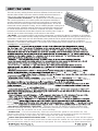
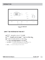
This unit has many exciting features which are different from those found on
standard PTAC models. The owner must be familiar with these features in
order to fully understand the operation and capability of the unit.

Your product
that
is
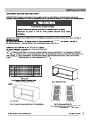
s ps the inside air from side
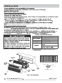
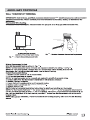
We recommend always to use a Frigidaire sleeve.
CONTROL
PAN
CONDENSATION DRAIN KIT
EL
When units are shipped with a sleeve:
When units are shipped without a sleeve:
CONDENSER
6
(A) GASKET
(B) MOUNTING PLATE
(C) 1/2"O.D.
DRAIN TUBE
ARCHITECTURAL ALUMINUM OUTDOOR GRILLE

Frigidaire
RIGIDAIRE
RIGIDAIRE GRILLE
ing
(see
Frigidaire GE’s
C , the actual baffle
kit m
look image n
5

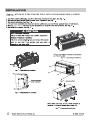
ATION OF A FRIGIDAIRE PTAC INTO A FRIGIDAIRE WALL SLEEVE
8
9
0
1
2
8
9
10
11
12
unit to sleeve
6

7
LCDI
Turn off electrical power before service or installation.
230V
20A
230V
15A
230V
30A
Table 1—LCDI DETECTION DEVICE
3
2
3
Refer to Table 1 for LCDI detection device images.

the
screw
13
(For Ducted Installations Only)
10
4
18
4
15
NOTE: Upward air direction should only be used on ducted installations.
8

the
10
4
16
17
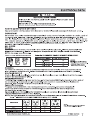
/Energy Saver: Cooling
/Energy Saver: Heating
4
1.
2.
The dip adjust accordingly in order to
allow the wall t control of the unit. When in wall mode, the control panel will be disabled.
3.Energy Saver ip Switches (Heating mode)
/Energy Saver
This is the most efficient mode for electrical usage.
5*6.
7.
the
4.Energy Saver ip Switches (Cooling mode)
9
cooling

SYSTEM CONFIGURATION
KEYPAD CONFIGURATION
Keypad Configuration
You can customize your unit additionally using the keypad configuration options.
To enter Keypad configuration
Connect the unit to power. Press and hold the "fan speed" and the "V
" for 5 continuous seconds, within
30 seconds of the unit being powered up.
If the unit has had power for more than 30
continuous seconds, keypad configuration cannot be made.
To scroll through the Keypad Configuration Options
Press and release the "fan speed" to select the keypad configurations.
The stored value will be displayed.
To modify configuration settings
Press and release the Setpoint " " or Setpoint " " buttons.
To exit Keypad Configuration
Keypad Configuration will end on its own 30 seconds after the last button press or when the "mode" on the
Keypad is pressed.
There are 4 configuration options
˖
1. Fahrenheit/Celsius Display Switch
:
Change between degrees Fahrenheit and Celsius on the display. An “F” indicates Fahrenheit display and
'C' indicates Celsius. Default is degrees “F”.
2. Indoor Air Temperature Sensor Biasing for Cooling mode
:
Sometimes known as an anticipator, the air temperature sensor bias is used to adjust the room air
temperature reading when in cooling mode. (Not normally required.)
3. Indoor Air Temperature Sensor Biasing for Heating mode
:
Sometimes known as an anticipator, the air temperature sensor bias is used to adjust the room air
temperature reading when in heating mode. (Not normally required.)
4. Indoor Temperature Display:
Change between showing the setpoint or desired temperature during heating and cooling modes (SP)
or displaying the actual room temperature during heating and cooling modes (AA). SP mode is the
default mode.
If SP is selected the desired setpoint temperature will be displayed during heating and
cooling modes, regardless of what the actual temperature is in the room.
If AA mode is selected, the room temperature will be displayed during heating,
cooling and fan only modes.
— If the mode button has been changed to either heating or cooling modes, setpoint will be displayed
for 10 seconds. After the 10 seconds, the room temperature will again be displayed.
— If the on/off button is depressed (when the unit is off ) and the last mode was either cooling or
heating mode, the setpoint will be displayed for 10 seconds before displaying room temperature.
— During heating and cooling modes, if either the up or down setpoint key is depressed, the display
will show the setpoint for 10 seconds. Then the room temperature will be displayed again.
Switchover between Emergency Auto Cooling Allowed and Emergency Auto Cooling
Rejected:
Press " " or " V " to switch between the display of Emergency Auto
Cooling
Allowed and Emergency Auto Cooling Rejected.
Emergency Auto Cooling Allowed: the diode displays CA.
Emergency Auto Cooling Rejected: the diode displays
CD.
10
2010 Electrolux Home Products, Inc. All rights reserved.
V
V
V
Auto cooling operation:
o
If this function is activated and room temperature reaches 85 F while the unit is in
the "STOP" setting, the unit will automatically start in air conditioning operation and will
shut off when the room temperature reach 80
o
F.

4.
.unit
5.
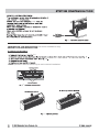
"fan speed"
It is used for setting high, low or auto fan speed. The
corresponding LED will be
lit when selected.
6. "timer"
It is used for setting the timer function.
"ON-OFF"
"mode"
"V"
"
V
"
11
fan
speed
on·off
on·off
mode
temp/timer
auto
low
hi
indoor
temp/timer
dry
cool
fan
heat
timer
setpoint
timer
Dry,

7. Timer function
(1) Timer ON: When the unit is off, timer ON can be set. Setting range is 0.5~24h. When timer ON
time is reached, the system will operate according to the set mode.
(2) Timer OFF: When the unit is off, timer OFF can be set. Setting range is 0.5~24h. When timer
OFF time is reached, the system will stop operation.
(3) Timer setting: Press "timer" to set timer function and "
timer
" icon will be on. The
time can be
adjusted by pressing " " or "V"
buttons.
The range of timer setting is from 0.5h to 24h.
5 seconds after timer setting, the
timer function will be activated and
"
timer
"
icon will be on.
(4) Timer preview: When timer function has been set, press "timer" to preview the remaining
time of timer.
(5) If timer function has been set, turning the unit or power on/off failure will cancel timer setting.
OPERATION
V
2

the
18
19
21
S 19
control panel guard
two Low fan Hi fan
L
H
on page 17

20
ncorrect
21
20
21
Frigidaire on-
they
error the can i
23
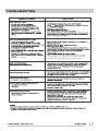
Table 5—STATUS LED Indicator
Definitions
1
Indoor air temp sensor open/short
8-segment display ‘F1’, with STATUS light flash 1 times and off 3 sec, repeat
2
Indoor coil sensor open or short
8-segment display ‘F2’, with STATUS light flash 2 times and off 3 sec, repeat
3
Outdoor coil sensor open/short
8-segment display ‘F4’, with STATUS light flash 3 times and off 3 sec, repeat
4
Freeze Guard protection
8-segment display ‘FP’
5
Indoor coil freeze protection
STATUS light flash 5 times and off 3 sec, repeat
6
Outdoor coil high temp protection STATUS light flash 6 times and off 3 sec, repeat
7
Defrost (heat pump type) STATUS light flash 7 times and off 3 sec, repeat
8
Indoor coil high temp protection STATUS light flash 8 times and off 3 sec, repeat
9
Thermostat wiring error
STATUS light flash 9 times and off 3 sec, repeat
NOTE: When status
light is flashing, it will
be ON for 1 seconds
and OFF for anothe
r
1 seconds.
4

23
o days (or sooner depending on application).
Product failure due to improper care or lack of maintenance is not covered by warranty
24
25
Product failure due to improper care or lack of
maintenance is not covered by warranty
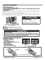
15
Coil on outdoor side of unit should be checked annually. Unit will need to be removed from its sleeve to inspect
dirt build-up that can occur inside of the coil. If clogged with dirt or soot, coil should be professionally cleaned.
Under extreme conditions, more frequent cleanings may be required.
Clean the coils and basepan with a soft brush and compressed air or vacuum. A pressure washer may also be
used, but be aware that the aluminium fins must not be bent. Use a gental up and down motion in the direction
of the vertical aluminium fins when pressure washing coils.

16
(Best to use compressed air.)

17
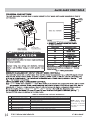
LCDI
LCDI
There is a protective time delay (approx.3 minutes) on starting the
compressor after a power outage (or restarting after it has been
turned off), to prevent tripping of the compressor overload.
Compressor is not running.

2010 Electrolux Home Products, Inc. All rights reserved.
18
SAFETY PRECAUTIONS
SAFETY PRECAUTIONS
DANGER! Avoid Serious Injury or Death
1. Do not attempt to install air conditioner by yourself.
2. This air conditioner contains no user-serviceable parts. Always call an authorized
Electrolux servicer for repairs.
3. When moving the air conditioner, always call an authorized Electrolux servicer for
disconnection and re-installation.
4. Do not insert or place fingers or objects into the air discharge area in the unit.
5. Do not start or stop the air conditioner by unplugging the power cord or turning
off the power at the electrical box.
6. Do not cut or damage the power cord.
7. If the power cord is damaged it should only be replaced by an authorized
Electrolux servicer.
8. In the event of a malfunction (sparks, burning smell, etc.) immediately stop the
operation, disconnect the power cord, and call an authorized Electrolux servicer.
9. Do not operate the air conditioners with wet hands.
10. Do not pull on the power cord.
11. Do not drink any water that is drained from the air conditioners.
CAUTION! Avoid Injury or damage to the unit or other property
1. Provide occasional ventilation during use. Do not direct airflow at fireplaces or
other heat related sources as this could cause flare ups or make units run
excessively.
2. Do not place containers containing water on unit.
3. Turn off the air conditioner at the power source when it will not be used for an
extended period of time.
4. Periodically check the condition of the unit’s installation base for any damage.
5. Do not apply heavy pressure to the radiator fins of the units.
6. Operate the unit with air filters in place.
7. Do not block or cover the intake grille, discharge area and outlet ports.
8. Ensure that any electrical/electronic equipment is one yard away from the unit.
9. Do not use or store flammable gases near the unit.
INSTALLATION WARNINGS
1. Carefully read the installation section of this manual before beginning.
2. Follow each step as shown.
3. Observe all local, state, and national electrical codes and by qualified, licensed,
authorized personnel only.
4. Pay attention to danger and safety notices.

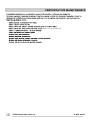
MAJOR APPLIANCE LIMITED WARRANTY
19
.devresersthgirllA.cnI,stcudorPemoHxulortcelE9002
Exclusions
1. Products with original serial numbers that have been removed, altered or cannot be readily determined.
This warranty does not cover the following:
2. Product that has been transferred from its original owner to another party or removed outside the USA or
Canada.
3. Rust on the interior or exterior of the unit.
4. Products purchased "as-is" are not covered by this warranty.
5. Service calls which do not involve malfunction or defects in materials or workmanship,
or used other than in accordance with the provided instructions.
6. Service calls to correct the installation of your appliance or to instruct you how to use your appliance.
7. Expenses for making the appliance accessible for servicing, such as removal of trim, cupboards, shelves,
etc., which are not a part of the appliance when it is shipped from the factory.
8. Service calls to repair or replace appliance light bulbs, air filters, water filters, other consumables, or knobs,
handles, or other cosmetic parts.
9. Surcharges including, but not limited to, any after hour, weekend, or holiday service calls, tolls, ferry trip
charges, or mileage expense for service calls to remote areas, including the state of Alaska.
10. Damages to the finish of appliance or facility incurred during installation, including but not limited to floors,
cabinets, walls, etc.
11. Damages caused by: services performed by unauthorized service companies; use of parts other than
genuine Electrolux parts or parts obtained from persons other than authorized service companies; or external
causes such as abuse, misuse, inadequate power supply, accidents, fires, or acts of God.
DISCLAIMER OF IMPLIED WARRANTIES; LIMITATION OF REMEDIES
CUSTOMER'S SOLE AND EXCLUSIVE REMEDY UNDER THIS LIMITED WARRANTY SHALL BE PRODUCT REPAIR OR
REPLACEMENT AS PROVIDED HEREIN. CLAIMS BASED ON IMPLIED WARRANTIES, INCLUDING WARRANTIES OF
MERCHANTABILITY OR FITNESS FOR A PARTICULAR PURPOSE, ARE LIMITED TO ONE YEAR OR THE SHORTEST
PERIOD ALLOWED BY LAW, BUT NOT LESS THAN ONE YEAR. ELECTROLUX SHALL NOT BE LIABLE FOR
CONSEQUENTIAL OR INCIDENTAL DAMAGES SUCH AS PROPERTY DAMAGE AND INCIDENTAL EXPENSES
RESULTING FROM ANY BREACH OF THIS WRITTEN LIMITED WARRANTY OR ANY IMPLIED WARRANTY. SOME
STATES AND PROVINCES DO NOT ALLOW THE EXCLUSION OR LIMITATION OF INCIDENTAL OR CONSE-
QUENTIAL DAMAGES, OR LIMITATIONS ON THE DURATION OF IMPLIED WARRANTIES, SO THESE LIMITATIONS
OR EXCLUSIONS MAY NOT APPLY TO YOU. THIS WRITTEN WARRANTY GIVES YOU SPECIFIC LEGAL RIGHTS.
YOU MAY ALSO HAVE OTHER RIGHTS THAT VARY FROM STATE TO STATE.
If You Need
Service
Keep your receipt, delivery slip, or some other appropriate payment record to establish the warranty period
should service be required. If service is performed, it is in your best interest to obtain and keep all receipts.
Service under this warranty must be obtained by contacting Electrolux at the addresses or phone
numbers below.
This warranty only applies in the USA and Canada.
In the USA, your appliance is warranted by Electrolux Major Appliances North
America, a division of Electrolux Home Products, Inc. In Canada, your appliance is warranted by Electrolux Canada Corp.
Electrolux authorizes no person to change or add to any obligations under this warranty. Obligations for service and parts under
this warranty must be performed by Electrolux or an authorized service company. Product features or specifications as described
or illustrated are subject to change without notice.
USA
1.866.942.1567
Canada
1.866.942.1567
Electrolux Canada Corp.
5855 Terry Fox Way
Mississauga, Ontario, Canada
L5V 3E4
Electrolux Major Appliances-North America
10200 David Taylor Drive
Charlotte NC 28262
Your appliance is covered by a limited two-year warranty and a limited 3-5 year warranty on the sealed system (the compressor,
condenser, evaporator and tubing). For two years from your original date of purchase, Electrolux will pay all costs for repairing or
replacing any parts of this appliance that prove to be defective in materials or workmanship when such appliance is installed,
used and maintained in accordance with the provided instructions. From the third to the fifth year from your original purchase
date, Electrolux will repair or replace any parts in the Sealed Refrigeration System (compressor, condenser, evaporator and
tubing) that prove to be defective in materials or workmanship. In years 3-5, the consumer will be responsible for diagnostic,
labor and parts costs as well as any removal, transportation and reinstallation expenses which are incurred during service on
components other than those covered under the Sealed Refrigeration System 5-year warranty.

-
 1
1
-
 2
2
-
 3
3
-
 4
4
-
 5
5
-
 6
6
-
 7
7
-
 8
8
-
 9
9
-
 10
10
-
 11
11
-
 12
12
-
 13
13
-
 14
14
-
 15
15
-
 16
16
-
 17
17
-
 18
18
-
 19
19
-
 20
20


Ask a question and I''ll find the answer in the document
Finding information in a document is now easier with AI
Related papers
-
Frigidaire ELECTRONIC CONTROL AIR CONDITIONER User manual
-
Frigidaire FRP12ETT2A Owner's manual
-
-
Frigidaire FGRQ0833U1 User guide
-
-
-
Frigidaire FFMS221SQ2 English
-
-
-
Frigidaire FFHP094WS1 User manual
Other documents
-
Kenmore 22-73039 Warranty
-
Durastar DRAC14A24WJ1NA User guide
-
-
Kenmore 4.2 cu. ft. Freestanding Gas Range w/ Broil & Serve Drawer - Black Manufacturer's Warranty
-
Amana PBH073G35CC User manual
-
Emerson Quiet Kool EATC12RSE1T Installation guide
-
 Friedrich Air Conditioning PDE07K3SG Owner's manual
-
SoleusAir HCC-C15HP-A User manual
-
Friedrich Heat Pump 920-087-09 User manual
-
