Page is loading ...

OPERATION MANUAL
MP-D SERIES
STEREO POWERED MIXER

PAGE 13
Specifications
Block diagram

PAGE 1
PAGE 12
Introduction
Precautions
Control panel
Channel control section
mono input section
stereo input section
Master control section
Rear panel
Application Example
Specification
General Specifications
Input Specifications
Output Specifications
Dimensions/weight
Diagram of dimension
Block system diagram
Contents
Introduction
For the variety level signal input
and the convenience of usage, the
MONO input channel has a MIC input
socket, a LINE input socket and a input
level attenuation switch. Every channel
has HI, MID, LOW equalization circuit,
AUX output and EFF send. There is a
7-band graphic equalizer for the LEFT
& RIGHT outputs to embellish the
timbre. And the b
. The
unit also has a stereo playback input
channel.
Besides stereo PA output , this
series mixer also has, mixing output,
AUX outputs and record outputs.
Furthermore, you can use headphone
to monitor, headphone volume can be
adjusted separately.
The built-in power amplifier has
manifold protectors and uses air cooling
for heat emission.
This series mixer has consummate
functions and perfect shape.
Thank you for purchasing the MP-D
series powered mixer, it have two
varieties in this series, they are MP-8D
and MP-12D. MP-8D has 4 mono input
channels and 2 stereo input channels, it
can provide output power 2X175 watts
for 8 ohms load or 2X300 watts for 4
ohms load; MP-12D has 8 mono input
channels and 2 stereo input channels, It
can provide output power 2X300 watts
for 8 ohms load or 2X500 watts for 4
ohms load. They are excellent power
mixer suitable for a wide variety of input
sources.
uilt in DSP effect
processor with 16 kinds of effects
W1
W
D:422
54
H:160
8
135
45 45
MODEL
MP-8D
MP-12D
W1
W
362 396
482 516
Unit: mm
Specifications
Dimensions
2 3 4 5 6 7 8
BAL BAL

PAGE 11
PAGE 2
Precautions
Location
Keep the unit away from locations where it
is likely to be exposed to high
temperatures or humidity - such as near
radiators, stoves, etc. Also avoid locations
are subject to excessive dust accumulation
or vibration which could cause mechanical
damage and locations subject to strong
electromagnetic fields, such as close to
broadcast equipment.
1.
Ventilation
The unit has ventilation slots on the side
panel and bottom panel.
Do not block these vents.
2.
Avoid physical shocks
Strong physical shocks to the unit can
cause damage.
Handle it with care.
3.
Do not open the case or attempt repairs
or modifications yourself
This product contains no user - serviceable
parts. Refer all repair or maintenance to
qualified engineer.
4.
Always power off before making
connections
Always turn the power off before
connecting or disconnecting cables.
This is important to prevent damage to
the unit itself as well as other connected
equipment.
5.
Handle cables carefully
Always plug and unplug cables -
including the AC power cord - by
gripping the connector, not the cord.
6.
Clean with a soft dry cloth
Never use solvents such as benzine or
thinner to clean the unit. Wipe clean
with a soft, dry cloth.
7.
Always use the correct power supply
Make sure that the power supply
voltage specified on the rear panel
matches your local AC mains supply.
Also make sure that the AC mains
supply can deliver more than enough
current to handle all equipment used in
your system.
8.
SAFETY INSTRUCTIONS!
WARNING - TO REDUCE THE RISK OF FIRE OR ELECTRIC SHOCK, DO NOT
EXPOSE THIS
UNIT TO
RAIN
OR
MOISTURE.
CAUTION:
TO REDUCE THE RISK OF ELECTRIC SHOCK, DO NOT REMOVE COVERS (OR
BACK). NO USER-SERVICEABLE PARTS
ARE INSIDE. REFER ALL SERVICING
TO A QUALIFIED SERVICE PERSONNEL.
Input Output Maximum voltage gain
L/R POWER OUT 94dB
L/R ST. OUT 72dB
MONO OUT 74dB
AUX SEND 74dB
EFF SEND 76dB
MIC IN
REC OUT 58dB
LINE IN (mono) 52dB
LINE IN (stereo) 26dB
AUX IN 26dB
Maximum voltage gain
2TR IN
L/R ST. OUT
26dB
Total Harmonic
Distortion
20Hz 20KHz 0.5%
Frequency Response
20HZ 20KHZ 1dB 2dB
Noise
122dB Equivalent Input Noise
Channel Equalization
HIGH 15KHZ 15dB
MID 0.1~8KHz or 2.5KHZ 15dB
LOW 80HZ 15dB
ST. OUT
Graphic Equalization
125HZ 250HZ 500HZ 1KHZ 2KHZ 4KHZ 8KHZ 12dB
Channel Peak
Indicator
The peak LED will illuminate approximately 3dB before clipping
Power Requirements
5%
AC115V/230V , 50Hz~60Hz
-10%
Power Consumption
1.5KVA(MP-8D) 2.5KVA(MP-12D)
Dimensions (WxHxD)
406 143 422 mm (MP-8D), 526 143 422 mm (MP-12D)
Weight
Specifications
General specification

PAGE 3
PAGE 10
Control panel
Channel control section (mono input section)
PEAK indicator
5
This red LED will warn you when an excessively high signal
level is present in the channel. It will be light when the signal
level is too strong to the unit will be overload.
GAIN control
4
Use this knob to adjust the level of the input signal to the
optimal level. For the best balance of S/N ratio and dynamic
range, adjust this knob so that the peak indicator lights
occasionally.
For Mic inputs connected to the XLR connector, the range is
+4dB~-60dB. For line inputs connected to the phone
connector, the range is +24dB~-40dB.
5
HIGH, MID, LOW 3-band equalizer
6
7
8
These knobs are used for adjusting (increase or decrease) the
signal level at the follow frequencies:
HIGH: 15KHz max control range +/-15dB
MID : MID FRQ control the center frequency
Control range 0.1~8KHZ.
MID control the signal lever
The max control range +/-15dB
LOW: 80Hz max control range +/-15dB
3
15
2
1
4
5
6
7
8
9
10
11
12
13
14
1
This is balanced microphone input XLR.
The rated input level: -60dB
This socket can offer +48V phantom power for
corresponding microphone when the phantom power
switch is turned on.
2
This is a balanced line input 1/4 JACK.
The rated input level: -40dB
LINE
PAD switch
3
This pad switch provides 20dB of level reduction. If the input
signal level is too high and the GAIN control will not reduce
it sufficiently, use this Pad switch.
4
AUX controls
9
This knob is used to control the signal level feed to the AUX
bus, It is set at front of the channel fader, so it is independent of
the fader location
MIC microphone input
INPUT Number
Input
mode
Input
impedance
Rated input
level
Connector
MIC IN
6(MP-8D)
10(MP-12D)
2.5K 60dB
XLR
LINE IN
(mono)
4(MP-8D)
8(MP-12D)
Balanced
47K
-40dB
6.35phone jacks
stereo
LINE
(stereo)
2 Unbalanced
10K
-10dB 6.35phone jacks
AUX RETURN
(1L~2R)
2 Unbalanced
10K
-10dB 6.35phone jacks
2TR IN
(L/R)
1 Unbalanced
10K
-10dB RCA
OUTPUT
Output
Mode
Load
Impedance
Output power or output level Connectors
MP-8D MP-12D
L/R Power out Unbalanced
8
2 200W
2 300W
2 300W
2 525W
Speakon and
binding post
L/R ST. OUT Unbalanced
600 Rated 4dB
6.35phone
jacks
MONO OUT Unbalanced
600 Rated 4dB
6.35phone
jacks
AUX OUT Unbalanced
600 Rated 4dB
6.35phone
jacks
EFF SEND Unbalanced
600 Rated 4dB
6.35 phone
jacks
REC OUT Unbalanced 10k Rated 10dB RCA
HEAD PHONE Unbalanced
40
Rated 5mw
6.35 stereo
phone jacks
Specifications
Input specifications
Output specification

PAGE 9
PAGE 4
ST.L
ST.R
AUX
E
E
PF
F
F
F
F
L
PFL CTRL
BA
PANPAN
AUX1
ON
+V
PFL
PEAK
LOW
MID
HIGH
HA
GAIN
MID FRQ
LINE IN
2
3
1
MIC IN
-20dB
EQ
PAD
-20dB
+48V
Control panel
EFF control
10
This knob is used for control feed
to the EFF bus, it has been set after the channel
fader, so it is enslaved to the fader position.
Adjust this knob when you use effector on this
channel.
the signal level
PAN control
11
This konb is used for distributing the signal level
of the channel feed to L/R buses. They are equal
which are feed to bus when the knob locates in
the middle .
Channel "ON" switch
12
When turn the switch "ON" signal of the channel
will be sent to stereo L/R bus , AUX and EFF
buses.
When turn the switch "OFF" the output signal to
each bus will be muted completely. The switch
should be turned off for unused channels.
PFL switch(input channel)
13
This switch allows you to monitor the signal of the
input channel at the pre fader level. You can use
headphones to conveniently check the input signal
of a specific channel, or trouble-shoot a channel
that is having problems.
Channel fader
14
This fader is used for controlling the channel signal
level feed to the L/R buses, It can be adjusted for
level balance between channels. It should be pulled
down when the channel is not in use.
PHANTOM +48V
phantom power switch and indicator
This button switch is used for turning on or off the
+48V phantom power in the unit. The +48V phantom
power will exist on the input socket of four
corresponding microphone input channel when this
switch is pressed.
Notices: Slide down all channel fader before turning
on or off the switch;
Don't plug or unplug microphone after this
switch were turned on;
Don't turn on the phantom switch when a
dynamic microphone is in use.
15
Channel control section (mono input section)
RIGHT
LEFT
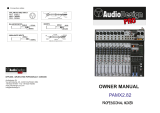
CD PLAYER
POWER AMP
EFFECT PROCESSOR
REC OUT L/R
TAPE IN L/R
LINE IN L/RLINE IN L/RMIC IN
STEREO POWER OUT
EFF SEND AUX RT L/RAUX SEND1
HEAD PHONES
Application example
2 3 4 5 6 7 8
BAL BAL

PAGE 5
PAGE 8
CH R CH L
OUTPUTS
MIN 4 ohm
OUT
1
1
STEREO
4 2
3
1
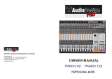
Rear panel
Rear panel
SPEAKON and BINDING POST
connectors for left&right power out
1
These connectors are all used for left&right
power out to speakers, they are wires in this way:
-PIN1+ connected in parallel to the red BINDING
POST;
-PIN1- connected in parallel to the black
BINDING POST.
Minimum impedance is 4 ohm.
It can output from the red BINDING POST, when
work on bridge mode. And the minimum
impedance is 8 ohm.
2
SOCKET for POWER CORD
AND FUSE-HOLDER
3
POWER SWITCH
4
1
3
2
4
6
7
8
9
10
11
13
12
14
5
Control panel
(Stereo input section)
MIC microphone input
1
This is an XLR type balanced connector for microphone, the
input level is -60dB. At this channel the signal will be feed to the L/R
main bus equally finally.
rated
These are two unbalanced phone jacks to which line level devices
can be connected, the rated input level is -10dB.
Only connect the source signal to L/MONO socket, when you use a
mono source, here, the right signal will be same as the left.
L/MONO R line inputs
2
-10dB LINE control
3
This switch is used for selecting the input sensitivity to get a right
level of the input signal. The gain of input channel will be reduced -
10dB when this switch is pressed.
Use this knob to adjust the level of the input signal to the optimal
level. For the best balance of S/N ratio and dynamic range, adjust
this knob so that the peak indicator lights occasionally.
5
GAIN microphones control
4
PEAK indicator
5
This indicator detects the signal level at a point after the EQ (pre
fader). It will be light at 3dB before clipping to remind that the signal
level is too strong to the unit will be overload.
These knobs control high mid and low equalization at the following
frequencies.
HIGH: 15KHz, maximum effect +/-15dB
MID: 2.5KHZ,maximum effect +/-15dB
LOW: 80Hz, maximum effect +/-15dB
HIGH, MID, LOW equalizer
6
7
8
AUX controls
9
This knob is used to control the signal level feed to the AUX bus, It is
set at front of the channel fader, so it is independent of the fader
location
EFF control
10
This knob is used for control feed to the EFF bus, it
has been set after the channel fader, so it is enslaved to the fader
position. Adjust this knob when you use effector on this channel.
the signal level
BAL
Balance control
11
This knob adjusts the left/right location of the stereo input signal.
Channel ON switch
12
Push down this switch, signal of the channel will be sent to the stereo
L/R bus.
23
AUX1 RET
This knob allows you adjusting the signal levels
send to the master channel, the signals are from
the AUX1 RET jack
24
AUX2 RET
This knob allows you adjusting the signal levels
send to the master channel, the signals are from
the AUX2 RET jack
25
2TR IN
This knob allows you adjusting the signal levels
send to the master channel, the signals are from
the 2TR IN jack
26
PHONES
This knob allows you adjusting the output signal
of the PHONES-socket
AUX RETURN
L/MONO
-10dB
R
HA
HA
AUX RETURN
20
EFF SELECT
This knob is used for selecting one from 16
kinds of effects. above (refer to the effects table
the selector).
21
EFF TO AUX
This knob is used for controlling the signal level
feed to AUX bus from the output of the internal
effector.
22
EFF TO MAIN
Main effect output level controller for
controlling the effect signal level of main
output.
20
19
22
21
23
24
25
26

PAGE 7
Control panel Control panel
PAGE 6
Master control section
Master control section
1
5
6
7
9
2
3
10
8
14
17 18 15 16
20
19
22
21
23
24
25
26
11
12
13
4
REC OUT
1
These two RCA connectors can output stereo
signals (left and right) for tape recorder.
The rated output level: -10dB
These two RCA connectors are used for receiving
stereo signals from stereo signal sources.
The rated output level: -10dB
2
2TR IN
AUX RET1 AUX RET2
3
4
These are two auxiliary input phone jacks.
The rated output level: -10dB
Only connect the source signal to L/MONO
socket, when you use a mono source, here, the
right signal will be same as the left.
This is a unbalanced phone jack for sending
auxiliary output signals. They can be linked to a
monitor outside or linked to a sub power
amplifier.
AUX SEND
5
This is jack for sending EFF output signals. It
also can be linked to a switch to control the
built-in effects processor.
EFF SEND/FT SW
6
PHONES
7
A set of stereo headphones can be connected
to this jack. Use this headphones you can
monitor the main out signals or group out
signals or the signals selected by channel PFL
switch, the signal you hear just like you see on
the LED meter.
STEREO OUT L/R
8
9
These are two unbalanced jacks for sending
stereo output signals of left or right channel.
The rated output level: 0dB
MONO OUT
10
This is a unbalanced jack for sending stereo
output signals of both left and right channels.
The rated output level: +4dB
11
POWER
This LED will be light, when power on.
12
This level meter indicates the signal level of
the stereo output. The built-in power
amplifier's output level is also synchronal
with this meter. The upper red LEDs
indicate the max output level of the built-in
amplifier. The monitor point is based upon
the POWER AMP SELECT switch.
LED LEVEL METER
13
POWER AMP SELECT
When the it is on the top, two power
amplifier's channels amplify mixer's
left&right channel signals separately. When
it’s on the middle ,one of the power
amplifier's channel amplify the mixing
signals of mixer's left&right channels.
Another power amplifier's channel amplify
the mixer's monitor signals When it’s on the
bottom, two power amplifier's channels
working at the bridge mode, amplify mixer's
mixing signals of left&right channels.
.
PFL switch (input channel)
13
This switch allows you to monitor the signal of the
input channel at the pre fader level. You can use
headphones to conveniently check the input signal
of a specific channel, or trouble - shoot a channel
that is having problems.
Channel fader
14
This fader controls the output level of the input
channel signal, adjusting the volume balance
between channels. Faders of channels not in use
should be pulled down.
EF F
MID
BA
BA
BALANCE
ON
LOW
EQ
HIGH
EQ
AUX
+V
PFL
HA
HA
L/MONO
LINE IN
R
-10dB
-20dB
AUX control
16
This slide fader adjust the final output level at
AUX output socket.
17
Stereo L master control
These slide fader are used for adjusting the final
output level at the LEFT stereo output socket.
Stereo R master control
18
These slide fader are used for adjusting the final
output level at the RIGHT stereo output socket.
19
EFF SEND
This knob is used for controlling the signal level
feed to the internal effector from all input
channels and also controlling the signal level
output from the EFF SEND sockets.
Graphic equalizer (7 band)
14
Since this equalizer is set before ST.OUT, it
allows you to make fine adjustments in
equalization to the overall output, for sound field
compensation or to prevent feedback.
MAIN (MONO)control
15
This slide fader adjust the final level which
merge L/R channel to MONO channel (output
from MONO OUT socket)
/