Page is loading ...

7160-1321 & 7160-1453
Zebra L10 Tablet Dock
A
INST-902
Printing Spec:
PS-001
© Copyright 2019 Gamber-Johnson, LLC
This instruction sheet is for the Zebra L10 Tablet Dock only. For instructions
on features, set-up, and operation of the computer, please refer to the manual
provided by Zebra with the tablet.
This dock is designed to be used with a variety of Gamber-Johnson mounting
systems. Installation instructions for other Gamber-Johnson products are
provided with each individual product.
This instruction sheet is for the following products:
Item No. 7160-1321-00
Item No. 7160-1321-01
Item No. 7160-1321-05
Item No. 7160-1453-00
Item No. 7160-1453-01
1/8
If you need assistance or have questions, call Gamber-Johnson at 1-800-456-6868
Form
Revision
Product
INSTALLATION INSTRUCTIONS
Product Mounting Disclaimer
Gamber-Johnson is not liable under any theory of contract or tort law for any loss, damage, personal injury, special, incidental or consequential damages for personal injury or other damage
of any nature arising directly or indirectly as a result of the improper installation or use of its products in vehicle or any other application. In order to safely install and use Gamber-Johnson
products full consideration of vehicle occupants, vehicle systems (i.e., the location of fuel lines, brake lines, electrical, drive train or other systems), air-bags and other safety equipment is
required. Gamber-Johnson specifically disclaims any responsibility for the improper use or installation of its products not consistent with original vehicle manufactures specifications
and recommendations, Gamber-Johnson product instruction sheets, or workmanship standards as endorsed through the Gamber-Johnson Certified Installer Program.

IMPORTANT SAFETY INFORMATION FOR INSTALLERS
Safety is dependent on the proper installation and servicing of this docking station. It is important
to read and follow all instructions before installing this product.
To properly install a Gamber-Johnson docking station you must have a good understanding of
automotive electrical procedures and systems, along with proficiency in the installation and service
of aftermarket vehicle equipment.
There are no adjustments required at any time of the electrical components within the docking
station.
Opening the docking station will void the product warranty.
During Installation:
DO NOT
connect this docking station to the vehicle battery until:
All other electrical connections are made
1.
Mounting of all components is complete
2.
Verification that no shorts exist in the entire system
3.
DO NOT
install equipment or route wiring or cords in the deployment path of any air bag.
When drilling into the vehicle, DO make sure that both sides of the surface are clear of anything
that could be damaged.
CAUTION:
If wiring is shorted to the frame, high current conductors can cause hazardous
sparks resulting in electrical fires or flying molten metal.
After installation:
Test the docking station to ensure that it is working properly.
File these instructions in a safe place and refer to them when performing maintenance or
re-installing.
WARNING
: Failure to follow all safety precautions and instructions may result in property
damage, serious injury, or death.
PRE-INSTALLATION RECOMMENDATOINS
Conduct a "Bench Test"
Gamber-Johnson strongly advises a "bench test" be conducted to verify all electronic and
software issues are resolved prior to installation:
Make sure the computer is operational by itself.
1.
Insert computer into the docking station and verify that the computer is
2.
operating in the dock.
Interconnect entire assembly and verify start-up of all components, including
3.
other equipment (printers, modems, scanners, etc.)
Gamber-Johnson recommends positioning of all mounts and equipment in the vehicle
prior to the actual install to verify that mounting locations are safe and practical.
2/8

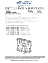
Docking Connector
Lock
Latch
Power Indicator Lights
USB Port and RS232 Switch
Access Cover
VESA 75mm
Mounting Pattern
100mm x 50mm
Mounting Pattern
Cable Tie Locations
ZEBRA L10 DOCKING STATION FEATURE IDENTIFICATON
3/8

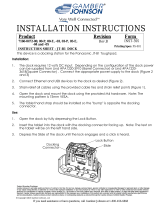
ZEBRA L10 DOCKING STATION PORT REPLICATION
4/8
All cables should be
secured to the dock
using cable ties as
illustrated at right
The orientation of the ethernet port makes the
cable release inaccessible by hand. Slide a
zip tie or small screwdriver under the cable to
release as shown at right.
(1x) Power Input - 19V DC
(1x) RS232 Serial - Power on Pin 9
See Page 5 for Details
(1x) Microphone
(1x) Headphones/Speaker
(2x) USB 2.0 - 4 Pin (500mA)
(2x) USB 3.0 - 9 Pin (900mA)
Function as USB 2.0 with Android
(1x) VGA - D-Sub 9 Pin
Not available on Android model
(1x) HDMI - 19 Pin
Not available on Android model
(1x) Ethernet RJ45
Not available on Android model

RS232 SWITCH ACCESS
Remove the screw that secures the back access panel
1.
in place (Figure 1)
Use needle nose pliers or tweezers to move the jumper
2.
to the desired position
The default jumper position is the left side to set Serial
3.
pin 9 to RI (Figure 2)
Alternatively, the bridge can be moved to the right side
4.
to set Serial pin 9 to 5V (Figure 3)
Close the access door and secure with the screw.
5.
5/8
CHANGING RS232 SETUP
Figure 1
Figure 2
Figure 3
USB ACCESS
Remove the screw that secures the back access panel
1.
in place (Figure 1)
Insert the desired USB module. The module must be
2.
sized appropriately to fit inside the closed unit. Do not
use this port for USB devices with a cable or devices
that prevent the access door from being closed.
Close the access door and secure with the screw.
3.
Do not use the dock with the rear access door open

TO DOCK THE TABLET
Insert the bottom of the tablet into
1.
the docking station (Figure 1)
Rotate the top of the tablet into the
2.
dock (Figure 2)
While holding the tablet in place,
3.
pull the latch down into the closed
position (Figure 3)
Use the key to lock and secure
4.
the latch when the dock is in use
DOCKING AND UNDOCKING THE TABLET
TO UNDOCK THE TABLET
Unlock the latch
1.
Flip the latch up to release the tablet
2.
Pull the tablet out of the dock from
3.
the top of the tablet
Figure 2
Figure 3
Figure 1
6/8

ASSEMBLY
Align the pogo connector with the cutout in the
1.
bottom of the cradle (see image at right).
Insert the front of the cradle first, then press the
2.
back of the cradle onto the docking module until
it clicks into place.
Use the parts from the hardware bag labeled
3.
7120-0941 to secure the module to the cradle.
The (4) #10 nuts fit into the locations marked in
4.
the image below with the letter A. Insert the #10
screws through the back of the docking module
and thread them into the nuts on the front of the
cradle.
The (4) #4 flat head screws thread into the
5.
module through the bottom of the cradle at the
locations marked in the image below with the
letter B.
Note: These images show a cradle with the RF
pass-through module. The same assembly
process should be used with cradles that do not
include the RF unit.
7/8
JOINING THE ZEBRA L10 MODULE TO A CRADLE

Gamber-Johnson LLC, 3001 Borham Ave., Stevens
Point, WI, 54481, USA, 715-344-3482
Regulatory Certification Information
Regulatory Model #: 7160-1321, 7160-1543
GJ Model #'s: 7160-1321-00, 7160-1321-01, 7160-1321-05
7160-1543-00, 7160-1543-01
Descriptions: Dock-Zebra L10 Tablet
Certifications:
EN 55032:2012/AC: 2013
•
FCC 47 CFR Part 15B Class B
•
AS/NZS CISPR 32: 2016
•
VCCI-CISPR 32: 2016
•
EN 50498:2010
•
ECE R10 Rev.5
•
IEC 62368-1(ed.2);am1;am2
•
E-Mark
•
This device complies with Part 15 of the FCC Rules. Operation is subject to the
following two conditions. (1) this device may not cause harmful interference, and
(2) this device must accept any interference received, including interfernece that
may cause undesired operation.
10R-04 7045
8/8
/