Porter-Cable PCB330BS User manual
- Category
- Power tools
- Type
- User manual

1
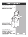
14 IN. (355 MM) BAND SAW
SCIE À RUBAN 355 MM (14 PO)
SIERRA DE CINTA PARA
BRANCO DE 355 MM (14 PULG.)
Instruction Manual
Manuel d’instructions
Manual de instrucciones
CATALOG NUMBER
PCB330BS
www.portercable.com
INSTRUCTIVO DE OPERACIÓN,
CENTROS DE SERVICIO Y
PÓLIZA DE GARANTÍA.
ADVERTENCIA: LÉASE ESTE
INSTRUCTIVO ANTES DE USAR
EL PRODUCTO.

2
TABLE OF CONTENTS
SECTION PAGE
PRODUCT SPECIFICATIONS ....................................................................................... 2
CALIFORNIA PROPOSITION 65 ................................................................................... 2
SAFETY GUIDELINES - DEFINITIONS ......................................................................... 3
POWER TOOL SAFETY ................................................................................................. 4
BAND SAW SAFETY ...................................................................................................... 5
ELECTRICAL REQUIREMENTS AND SAFETY ............................................................ 6
TOOLS NEEDED FOR ASSEMBLY ............................................................................... 7
CARTON CONTENTS .................................................................................................... 7
KNOW YOUR BAND SAW ............................................................................................. 9
GLOSSARY OF TERMS ................................................................................................. 10
ASSEMBLY AND ADJUSTMENTS ................................................................................. 11
OPERATION ................................................................................................................... 18
MAINTENANCE .............................................................................................................. 21
TROUBLESHOOTING GUIDE ....................................................................................... 22
ACCESSORIES AND ATTACHMENTS .......................................................................... 24
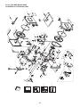
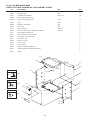
PARTS LIST .................................................................................................................... 25
WARRANTY ................................................................................................................... 28
MOTOR BLADE
Amps ............ 10 / 5 AMP Width ................. 1/8, 1/4, 3/8, 1/2 in.
Voltage ......... 120 / 240 V (3.2, 6.4, 9.5, 12.7 mm)
Hz ................. 60 Length ............... 93-1/2 in. (2374.9 mm)
Horsepower .. 1.5 HP (Max. Developed) CUTTING CAPACITY
Speed ........... 1630/2730 Feet per minute (No load) Throat ................ 13-5/8 in. (346 mm)
Type .............. Induction Height ................ 6 in. (152.4 mm)
DRIVE BELT A-26 SAWDUST PORT 2-1/2 in. O.D. (63.5 mm)
TABLE SIZE 16 x 16 in. (406.4 x 406.4 mm)
PRODUCT SPECIFICATIONS
To avoid electrical hazards, re hazards or damage to the tool, use proper circuit protection.
Use a separate electrical circuit for your tools. This band saw is wired at the factory for 110-
120/220-240 Volt operation. It must be connected to a 110-120 Volt / 10 Ampere or 220-240
Volt / 5 Ampere time delay fuse or circuit breaker. To avoid shock or re, replace power cord
immediately if it is worn, cut or damaged in any way.
Some dust created by power sanding, sawing, grinding, drilling and other construction
activities contains chemicals known to the state of California to cause cancer, birth
defects or other reproductive harm. Some examples of these chemicals are:
● Lead from lead-based paints,
● Crystalline silica from bricks and cement and other masonry products, and
● Arsenic and chromium from chemically-treated lumber.
Your risk from these exposures varies, depending on how often you do this type of work.
To reduce your exposure to these chemicals: work in a well ventilated area, and work
with approved safety equipment, such as those dust masks that are specially designed
to lter out microscopic particles.
Avoid prolonged contact with dust from power sanding, sawing, grinding, drilling and
other construction activities. Wear protective clothing and wash exposed areas with
soap and water. Allowing dust to get into your mouth, eyes, or lay on the skin may
promote absorption of harmful chemicals.
Use of this tool can generate and/or disperse dust, which may cause
serious and permanent respiratory or other injury. Always use NIOSH/
OSHA approved respiratory protection appropriate for the dust exposure. Direct particles
away from face and body.
2014/05 Printed in Taiwan
WARNING
!
CALIFORNIA PROPOSITION 65
WARNING
!
WARNING
!

3
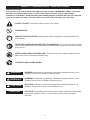
SAFETY GUIDELINES - DEFINITIONS
WARNING ICONS
Your power tool and its Instruction Manual may contain “WARNING ICONS” (a picture
symbol intended to alert you to, and/or instruct you how to avoid, a potentially
hazardous condition). Understanding and heeding these symbols will help you operate
your tool better and safer. Shown below are some of the symbols you may see.
SAFETY ALERT: Precautions that involve your safety.
PROHIBITION
WEAR EYE PROTECTION: Always wear safety goggles or safety glasses with
side shields.
READ AND UNDERSTAND INSTRUCTION MANUAL: To reduce the risk of injury,
user and all bystanders must read and understand instruction manual before using
this product.
SUPPORT AND CLAMP WORK
KEEP HANDS AWAY FROM BLADE: Failure to keep your hands away from the
blade will result in serious personal injury.
DANGER: Indicates an imminently hazardous situation which, if not
avoided, will result in death or serious injury.
WARNING: Indicates a potentially hazardous situation which, if not
avoided, could result in death or serious injury.
CAUTION: Indicates a potentially hazardous situation which, if not
avoided, may result in minor or moderate injury.
CAUTION: Used without the safety alert symbol indicates a potentially
hazardous situation which, if not avoided, may result in property
damage.
DANGER
!
WARNING
!
CAUTION
!
CAUTION

4
POWER TOOL SAFETY
GENERAL SAFETY INSTRUCTIONS
BEFORE USING THIS POWER TOOL
Safety is a combination of common sense,
staying alert and knowing how to use your
power tool.
To avoid mistakes that could cause serious
injury, do not plug the tool in until you have
read and understood the following.
1. READ and become familiar with the
entire Instruction Manual. LEARN
the tool’s application, limitations and
possible hazards.
2. KEEP GUARDS IN PLACE and in working
order.
3.
REMOVE ADJUSTING KEYS AND
WRENCHES. Form the habit of checking to
see that keys and adjusting wrenches are
removed from the tool before turning ON.
4. KEEP WORK AREA CLEAN. Cluttered
areas and benches invite accidents.
5. DO NOT USE IN DANGEROUS
ENVIRONMENTS. Do not use power tools
in damp locations, or expose them to rain or
snow. Keep work area well lit.
6. KEEP CHILDREN AWAY. All visitors and
bystanders should be kept a safe distance
from work area.
7. MAKE WORKSHOP CHILD PROOF with
padlocks, master switches or by removing
starter keys.
8. DO NOT FORCE THE TOOL. It will do the
job better and safer at the rate for which it
was designed.
9. USE THE RIGHT TOOL. Do not force the
tool or an attachment to do a job for which it
was not designed.
10. USE PROPER EXTENSION CORDS.
Make sure your extension cord is in good
condition. When using an extension cord,
be sure to use one heavy enough to carry
the current your product will draw. An
undersized cord will result in a drop in line
voltage and in loss of power which will cause
the tool to overheat. The table on page 6
shows the correct size to use depending on
cord length and nameplate ampere rating.
If in doubt, use the next heavier gauge. The
smaller the gauge number, the heavier
the cord.
11. WEAR PROPER APPAREL. Do not wear
loose clothing, gloves, neckties, rings,
bracelets or other jewelry which may get
caught in moving parts. Nonslip footwear
is recommended. Wear protective hair
covering to contain long hair.
12. ALWAYS WEAR EYE
PROTECTION. Any power tool can
throw foreign objects into the eyes
and could cause permanent eye
damage. ALWAYS wear Safety Goggles
(not glasses) that comply with ANSI Safety
standard Z87.1. Everyday eyeglasses
WARNING
!
have only impact–resistant lenses. They
ARE NOT safety glasses. NOTE: Glasses or
goggles not in compliance with ANSI Z87.1
could seriously injure you when they break.
13. WEAR A FACE MASK OR DUST
MASK. Sawing operation produces
dust.
14. SECURE WORK. Use clamps or
a vise to hold work when practical.
It is safer than using your hand
and it frees both hands to operate
the tool.
15. DISCONNECT TOOLS FROM POWER
SOURCE before servicing, and when
changing accessories such as blades, bits
and cutters.
16. REDUCE THE RISK OF UNINTENTIONAL
STARTING. Make sure switch is in the OFF
position before plugging the tool in.
17. USE RECOMMENDED ACCESSORIES.
Consult this Instruction Manual for
recommended accessories. The use of
improper accessories may cause risk of
injury to yourself or others.
18. NEVER STAND ON THE TOOL. Serious
injury could occur if the tool is tipped or if the
cutting tool is unintentionally contacted.
19. CHECK FOR DAMAGED PARTS. Before
further use of the tool, a guard or other part
that is damaged should be carefully checked
to determine that it will operate properly
and perform its intended function – check
for alignment of moving parts, binding of
moving parts, breakage of parts, mounting
and any other conditions that may affect
its operation. A guard or other part that is
damaged should be properly repaired
or replaced.
20. NEVER LEAVE THE TOOL RUNNING
UNATTENDED. TURN THE POWER
“OFF”. Do not walk away from a running
tool until the blade comes to a complete stop
and the tool is unplugged from the power
source.
21. DO NOT OVERREACH. Keep proper
footing and balance at all times.
22. MAINTAIN TOOLS WITH CARE. Keep
tools sharp and clean for best and safest
performance. Follow instructions for
lubricating and changing accessories.
23. DO NOT use power tool in presence of
ammable liquids or gases.
24. DO NOT operate the tool if you are under
the inuence of any drugs, alcohol or
medicationn that could affect your ability to
use the tool properly.
25. Dust generated from certain materials can
be hazardous to your health. Always operate
saw in well-ventilated area and provide for
proper dust removal.
26. WEAR HEARING PROTECTION to reduce
the risk of induced hearing loss.

5
BAND SAW SAFETY
1. TO AVOID INJURY from unexpected
movement, make sure the saw is on a
rm, level surface and properly secured
to prevent rocking. Make sure there is
adequate space for operating. Bolt
the saw to a support surface to
prevent slipping, walking or sliding
during operation.
2. UNPLUG AND TURN the saw off before
moving it.
3. USE THE CORRECT size and style
of blade.
4.
USE blades rated at 2700 FPM or greater.
5. MAKE SURE the blade teeth point down
and towards the table when installed
on unit.
6. BLADE GUIDES, SUPPORT BEARINGS
AND BLADE TENSION must be properly
adjusted to avoid accidental blade
contact and to minimize blade breakage.
To maximize blade support, always adjust
the upper blade guide and blade guard
so that it is 1/8 inch (3.2 mm) above
the workpiece.
7. TABLE LOCK HANDLE should be tight.
8. USE EXTRA CAUTION with large, very
small or awkward workpieces.
9. USE EXTRA SUPPORTS to prevent
workpieces from sliding off the table top.
Never use another person to support
the workpiece.
10. WORKPIECES must be secured so they
do not twist, rock or slip while being cut.
11. PLAN intricate and small work carefully to
avoid pinching the blade. Avoid awkward
operation and hand positions to prevent
accidental contact with
the blade.
12. SMALL PIECES should be secured with
jigs or xtures. Do not hold pieces that
are so small your ngers are under the
blade guard.
13. SUPPORT round work properly (with a
V-block or clamped to the miter gauge)
to prevent it from rolling and the blade
from biting.
14. CUT only one workpiece at a time. Make
sure the table is clear of everything
except the workpiece and guides before
turning the saw on.
15. ALWAYS WATCH the saw run before
each use. If there is excessive vibration
or unusual noise, stop immediately. Turn
the saw off. Unplug immediately. Do not
start the saw again until the problem has
been located and corrected.
16. TO FREE any jammed material, turn the
switch off. Remove the switch key and
unplug the saw. Wait for all moving parts
to stop before removing jammed material.
17. DO NOT LEAVE the work area until all
moving parts are stopped. To childproof
the workshop, shut off power to master
switches and remove the switch key from
the band saw. Store it in a safe place,
away from children.
For your own safety, read the entire
Instruction Manual before using the
band saw.
1. Wear eye protection.
2. Do not wear gloves, neckties or loose
clothing.
3. Make sure the saw is on a rm level
surface and properly secured.
4. Use only the recommended accessories.
5. Use extra caution with very large, very
small or awkward workpieces.
6. Keep hands away from the blade at all
times to prevent accidental injury.
7. Do not remove jammed or cutoff pieces
until the blade has stopped.
8. Maintain proper adjustment of blade
tension, blade guides and thrust bearings.
9. Hold the workpiece rmly against the
table.
10. Adjust the upper guide to clear the
workpiece.
WARNING
!

6
ELECTRICAL REQUIREMENTS AND SAFETY
POWER SUPPLY AND MOTOR SPECIFICATIONS
To avoid electrical hazards, re hazards,
or damage to the tool, use proper circuit
protection. Use a seperate electrical circuit for
your tool. Your saw is wired at the factory for
120 V operation. Connect to a 120 V, 10 Amp
circuit and use a 10 Amp time delay fuse or
circuit breaker. To avoid shock or re, if power
cord is worn, cut, or damaged in any way, have it
replaced immediately.
GROUNDING INSTRUCTIONS
This tool must be grounded while in use to
protect the operator from electrical shock.
IN THE EVENT OF A MALFUNCTION OR
BREAKDOWN, grounding provides a path of least
resistance for electric currents and reduces the
risk of electric shock. This tool is equipped with an
electrical cord that has an equipment-grounding
conductor and a grounding plug. The plug must be
plugged into a matching receptacle that is properly
installed and grounded in accordance with all local
codes and ordinances.
DO NOT MODIFY THE PLUG PROVIDED. If it will
not t the receptacle, have the proper receptacle
installed by a qualied electrician.
IMPROPER CONNECTION of the equipment
grounding conductor can result in risk of electric
shock. The conductor with the green insulation
(with or without yellow stripes) is the equipment
grounding conductor. If repair or replacement of
the electrical cord or plug is necessary, do not
connect the equipment grounding conductor to a
live terminal.
CHECK with a qualied electrician or service person
if you do not completely understand the grounding
instructions, or if you are not certain the tool is
properly grounded.
USE only 3-wire extension cords that have
three-pronged grounding plugs with three-pole
receptacles that accept the tool’s plug. Repair or
replace damaged or worn cords immediately.
Use a separate electrical circuit for your tool. This
circuit must not be less than #16 wire and should
be protected with a 10 Amp time lag fuse. Before
connecting the motor to the power line, make sure
the switch is in the off position and the electric
current is rated the same as the current stamped on
the motor nameplate. Running at a lower voltage will
damage the motor.
GUIDELINES FOR EXTENSION CORDS
USE THE PROPER EXTENSION CORD. Make
sure your extension cord is in good condition. Use
an extension cord heavy enough to carry the
WARNING
!
WARNING
!
current your product will draw. An undersized cord
will cause a drop in line voltage resulting in loss of
power, overheating and burning out of the motor.
The table below shows the correct size to use
depending on cord length and nameplate ampere
rating. If in doubt, use the next heavier gauge. The
smaller the gauge number, the heavier the cord.
Make sure your extension cord is properly wired
and in good condition. Always replace a damaged
extension cord or have it repaired by a qualied
technician before using it. Protect your extension
cords from sharp objects, excessive heat and damp
or wet areas.
This tool is for indoor use only. Do not expose to
rain or use in damp locations.
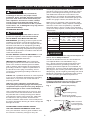
This tool is intended for use on a circuit that has
a receptacle like the one illustrated in Fig. 1.
Fig. 1 shows a three-pronged electrical plug and
receptacle that has a grounding conductor. If a
properly grounded receptacle is not available, an
adapter (Fig. 2) can be used to temporarily connect
this plug to a two-contact grounded receptacle. The
adapter (Fig. 2) has a rigid lug extending from it that
MUST be connected to a permanent earth ground,
such as a properly grounded receptacle box.
In all cases, make certain the receptacle is
properly grounded. If you are not sure, have a
qualied electrician check the receptacle.
MINIMUM GAUGE FOR EXTENSION CORDS (AWG)
Ampere Rating Total Length of Cord
More
Than
Not More
Than
120 V 25 50 100 150 ft.
(7.62 15.24 30.48 45.72 m)
240 V 50 100 200 300 ft.
(15.24 30.48 60.96 91.44 m)
AWG - American Wire Gauge
0 6 18 16 16 14
6 10 18 16 14 12
10 12 16 16 14 12
12 16 14 12 Not Recommended
WARNING
!
CAUTION
!
Fig. 1
Fig. 2
Three-Pronged Plug
Grounding Prong
Properly Grounded
Three-Pronged Receptacle
Grounding Lug Make sure this
is connected to
a known ground.
Two-Pronged
Receptacle
Adapter

7
240 VOLT SINGLE PHRASE OPERATION
To avoid injury, disconnect the motor from power
source outlet before reconnecting the wire.
The motor supplied with your machine is a dual
voltage, 120/240 volt motor. It is shipped ready-to-run
for 120 volt operation. However, it can be converted
for 240 volt operation, reconnect the motor wire as
the wiring diagram on page 20.
A qualied electrician should do the conversion, or
the machine can be taken to an Authorized Service
Center. When completed, the machine must conform
to the National Electric Code and all local codes
and ordinances.
The machine is converted by re-wiring the motor
for 240 volts, installing a 240 volt plug on the power
supply cord and replacing the switch with one that is
rated for 240 volt operation.
Be sure the 240 volt plug is only used in an outlet
having the same conguration as the plug illustrated
in Fig. 1.
No adapter should be used with the 240 volt plug.
In all cases, make certain that the receptacle in ques-
tion is properly grounded. If you are not sure, have a
qualied electrician check the receptacle.
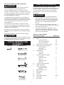
Combination square
Straight edge
Feeler gauge
(size 0.02 in.)
Phillips screwdriver
Adjustable wrench
Supplied Not Supplied
Hex key
12 mm wrench
WARNING
!
CAUTION
!
TOOLS NEEDED FOR
ASSEMBLY
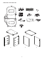
UNPACKING AND CHECKING CONTENTS
Carefully unpack the band saw and all its parts, and
compare against the list below and the illustration
on the next page. With the help of an assistant
place the saw on a secure surface and examine
it carefully.
● To avoid injury from unexpected starting or
electrical shock, do not plug the power cord
into a source of power during unpacking and
assembly. This cord must remain unplugged
whenever you are adjusting/assembling
the saw.
● The saw is heavy and should be lifted with
care. If needed, get the assistance of someone
to lift and move the saw.
● If any part is missing or damaged, do not
attempt to assemble the band saw, or plug in
the power cord until the missing or damaged
part is correctly replaced.
CARTON CONTENTS
WARNING
!
TABLE OF LOOSE PARTS
ITEM DESCRIPTION QUANTITY
A. Foot pads & hex nuts 4
B. Bag:
Carriage screws 16
Hex nuts w/ washers 16
Screw w/ washers 8
C. Door knob / hex screw / washer 1 each
D. Stand attachment hardware
Large washers 8
Hex nuts 4
Long hex bolts 4
E. Sawdust port 1
Hex bolts 2
Washers 2
F. Trunnion support hardware
Long bolt 1
Short hex bolts 2
Hex nut 1
Table lock knob 2
Washers 2
G. Trunnion support bracket 1
H. Table with insert 1
I. Power cord bracket 2
Cross head bolts 2
Hex key 1
J. Band saw with motor 1
K. Miter gauge 1
L. Top plate 1
M. Tool tray 1
N. Left / right side plate 1 each
O. Back plate 1
P. Door plate 1

8
UNPACKING YOUR BAND SAW
ABC
DE
HI
J
F
G
M
K
L
PN O

9
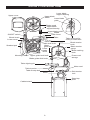
KNOW YOUR BAND SAW
Lower blade
support bearing
Lower blade
guide
Upper blade
wheel
Blade guard
Upper blade
support bearing
Upper blade guide
Blade
Table insert
Table Table removed for
clarity of illustration
Blade tension
knob
Blade tension
gauge
Blade tracking
knob
Power cord
storage
Motor cord
Stand top
plate
Cabinet stand
Table tilt stop bolt
Motor
Table trunnion
Table aligning pin
Upper
guide bar
Lower
blade
wheel
Table lock knob
Mounting holes
Sawdust port
Lower cover
Wheel brush
ON/OFF switch
Upper cover
Upper guide lock knob
Blade guide slide knob
Belt tension
bolt
Table tilt scale

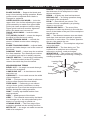
10
RESAW — A cutting operation to reduce
the thickness of the workpiece to make
thinner workpiece.
RESIN — A sticky sap that has hardened.
RIPPING CUT — A cutting operation along
the length of the workpiece.
R.P.M. — Revolutions per minute. The
number of turns completed by a spinning
object in one minute.
SAW BLADE PATH — The area of the
workpiece or table top directly in line with the
travel of the blade or the part of the workpiece
that will be cut.
SET — The distance between two saw blade
teeth tips, that are bent outward in opposite
directions to each other. The further apart the
tips are, the greater the set.
TRAILING EDGE — The workpiece edge last
cut by the blade.
WORKPIECE — The item being cut. The
surfaces of a workpiece are commonly
referred to as faces, ends and edges.
WORKTABLE — The surface on which the
workpiece rests while performing a cutting or
sanding operation.
GLOSSARY OF TERMS
BAND SAW TERMS
BLADE GUIDES — Support the blade and
keep it from twisting during operation. Blade
guides must be adjusted when blade is
changed or replaced.
UPPER GUIDE LOCK KNOB — locks the
upper slide. Use it after adjusting the upper
guide assembly to make sure upper blade
guide just clears workpiece before cutting.
Upper guide lock knob must be tightened
before the band saw is turned on.
TABLE LOCK KNOB — locks the table
in place.
TILT (BEVEL) SCALE — shows the degree
the table is tilted for bevel cutting.
BLADE TENSION KNOB — controls the
amount of blade tension when changing
blades.
BLADE TRACKING KNOB — adjusts blade
position so blade always runs in the center of
the wheel.
SAWDUST PORT — helps keep the machine
free from sawdust. The sawdust port makes
an excellent hook-up for a wet/dry vacuum.
ON/OFF SWITCH —
has a built-in child safety
lock. To lock the switch in the OFF position,
remove the switch key from the switch.
WOODWORKING TERMS
BEVEL CUT — An angle cut made through
the face of a workpiece.
COMPOUND CUT — A simultaneous bevel
and miter cut.
CROSSCUT — A cut made across the width
of the workpiece.
F.P.M. — Feet per minute. Used in reference
to the surface speed of the saw blade.
FREE HAND — Performing a cut without
using a fence (guide), hold-down or other
proper device to prevent the workpiece from
twisting during the cutting operation.
GUM — A sticky sap-based residue from
wood products.
HEEL — Misalignment of the blade.
KERF — The material removed by the blade
in a through cut, or the slot produced by the
blade in a non-through or partial cut.
LEADING EDGE — The front edge of the
workpiece pushed into the cutting tool rst.
MITER CUT — An angle cut made across the
width of a workpiece.
Kerf
Surface
Workpiece
Trailing
Edge
Saw Blade
Path
Leading Edge

11
ASSEMBLY AND ADJUSTMENTS
Estimated Assembly Time: 50 - 60 minutes.
For your safety, never connect plug to power
source receptacle until all assembly and
adjustment steps are complete, and you have
read and understood the safety instructions.
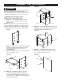
ASSEMBLING CABINET STAND
(FIG. A, A-1, A-2, A-3, A-4, A-5)
1. Bag “A” - Thread the feet (2) with the
hex nut (1) into each hole of two side
plates (3, 8).
NOTE: Adjust the level of stand. When the
feet are adjusted properly, turn the hex nuts
against the leg of side plate to secure them.
Loosen the hex nut before any adjustment.
2. Bag “B” - Attach R.H. side plate (3) (with
holes on side) to the tool tray (4) with
four carriage bolts (5) and hex nut
w/ washers (6).
3. Repeat above steps for the L.H. plate (8).
Securely tighten nuts.
4. Bag “B” - Attach top plate (7) to the
L.H. side plate (8) and R.H. plate (3)
with eight carriage bolts (5) and hex nut
w/ washers (6). NOTE: Top plate anges
t inside side plates.
1
2
3
WARNING
!
Fig. A
Fig. A-1
3
4
5
6
Magnet
Front
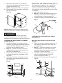
5. Bag “B” - Mount the back plate (9) to the
top plate (7) and tool tray (4), then fasten
with four screws w/ washers (10).
6. Bag “C” - Insert the door knob (11) to
the hole of door plate (12) with one hex
screw (13) and washer (14).
3
4
10
9
7
8
13
14
11
12
8
3
5
7
6
Magnet
Front
Fig. A-2
Fig. A-3
Fig. A-4

12
7. Mount the door plate (12) to the R.H.
side plate (3) hinges and fasten with four
screws w/ washers (10).
NOTE: Hinge goes behind side plate lip.
8. Place stand on level surface and adjust
the feet if needed.
NOTE: Make sure all screws and nuts are
tight and stand is on a stable surface before
mounting saw.
Although compact, this saw is heavy and
should be lifted with care. If needed, get the
assistance of someone to lift and move the saw.
ASSEMBLING BAND SAW TO CABINET
STAND (FIG. B)
1. Lift the saw body (1) and place on the
stand (2), aligning the mounting holes (3)
of the saw base with the four mounting
holes on the top plate of stand.
2. Bag “D” - Attach the band saw to the
stand with four long hex head bolts (4)
and four at washers (5).
3. Place a at washer (5) and hex nut (6)
on each bolt from the underside of the
top plate.
4. Hold bolt head with a separate wrench
and tighten all mounting bolts and nuts
with a wrench.
10
12 3
1
4
5
3
2
5
6
Front
Fig. A-5
WARNING
!
Fig. B
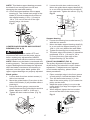
INSTALLING THE SAWDUST PORT (FIG. C)
The sawdust port has a 2-1/2 in. (63.5 mm,
O.D.) / 2-1/4 in. (57.2 mm, I.D.) diameter
opening, suitable for attaching to a wet/dry
vacuum hose to help keep the work area free
of sawdust.
1. Open the lower cover (1).
2. Bag “E” - Attach the sawdust port (2) to
the edge of the wheel cover, using the
hex head bolts (3) and washers (4).
3. Tighten the bolts (3) and close the cover.
ASSEMBLING THE BAND SAW TABLE
(FIG. D, E, F)
Mounting the trunnion support bracket
(Fig. D)
1. Place the trunnion support bracket (1) on
the saw body as shown, then align the
mounting holes.
2. Bag “F” - Place the washers (2) on the
hex head bolts (3), and insert into the
threaded holes, through the bracket and
saw body. Tighten the bolts.
3. Thread a nut (4) into the table stop
bolt (5) and the rear tab (6) on the
trunnion support bracket (1).
4.
Tighten the nut down onto the bracket tab.
3
2
6
1
5
4
Fig. C
2
3
4
1
Fig. D

13
Mounting the table (Fig. E, F)
5. Remove the table aligning pin (18) and
table insert (13) from the table.
6. Guide the table slot (14) over the saw
blade and rotate a 1/4 turn, so the slot is
perpendicular to the blade.
7. Bag “F” - Placing the lock knob bolts (10)
through the trunnion bracket holes (15)
as shown, lower the table onto the
trunnion bracket.
8. Place a lock knob (16) on each lock knob
bolt. Adjust the table by aligning the zero
scale mark to the scale pointer (17) and
tighten the knobs.
9. Replace the table insert (13), aligning
the indents.
10. Place the table aligning pin (18) in the
hole (19) at the front of the table, and
tighten it.
13 14
10
15
13 18
16
17
19
Fig. E
Fig. F
INSTALLING AND REMOVING BLADES
(FIG. G)
To avoid injury from accidental starting,
always turn the switch OFF and remove the
plug from the power source before moving,
replacing, or adjusting the blade.
Removing
1. Loosen the blade tension by turning the
blade tension knob (1) counterclockwise.
2. Remove the table insert (2) and remove
the table aligning pin (3) from the table.
3. Open the upper and lower wheel cover
doors (4).
4. Loosen the two Phillips screws (5) and
remove the upper blade guard (6).
5. Remove the blade (7) from the upper and
lower blade guides (8).
6. Carefully pull the blade from the side
slot (9) and from the wheels (10).
7. Swing the left side of the blade toward
you, turning the blade so it will t through
the slot (11) in the table, and remove.
NOTE: The available usage of blade
length is from 91-1/2 to 93-1/2 in.
(2324 to 2374.9 mm).
1
10
6
5
8
211
4
9
38
10
4
7
WARNING
!
Fig. G

14
Installing
1. Make sure the blade tension knob (1) is
turned counterclockwise enough to get
blade over pulleys.
2. Remove old blade as explained in
“Removing” section.
3. Guide the new blade (7) through the table
slot (11). Make sure the blade teeth are
pointing forward and down.
NOTE: To avoid lifting the workpiece, the
blade teeth must point downward toward
the table.
4. Swinging the left side of the blade away
and back, place the blade on the upper
and lower wheels (10).
5. Place the blade carefully between the
upper and lower blade guides (8).
6. Slide the blade into the slot (9) at the left
of the wheels, and make sure the blade is
positioned at the middle of the wheels.
7. Turning the blade tension knob (1)
clockwise, tighten the tension until the
blade is tight on the wheels.
8. Replace the upper blade guard (6) and
tighten the two Phillips screws (5).
9. Replace the table insert (2) and the table
aligning pin (3).
10. Adjust the blade tracking and tension
properly (See ADJUSTMENT
INSTRUCTIONS section) before
operating the band saw.
To avoid injury, the blade tension, tracking,
and upper and lower guides and bearings
must be properly adjusted before operating
the band saw. (See ADJUSTMENT
INSTRUCTIONS section)
Before operation always make sure the blade
is in center of table insert slot.
MITER GAUGE (FIG. H)
A miter gauge (1) is supplied with your band
saw to be used in the table slot (2) on the right
side of the blade. The miter gauge can be
adjusted from 0° to 60° right or left to maintain
an accurate angle for your workpiece.
WARNING
!
WARNING
!
Fig. H
1
2
INSTALLING POWER CORD STORAGE
(FIG. I)
1.
Bag “I” - Power cord brackets (1) are
provided for convenient cord storage. Attach
the power cord brackets to the back of the
saw body, as shown, with two Phillips head
screws (2). Tighten the screws.
2. Wrap the power cord onto the brackets
when the band saw is not in use. This can
prevent damage to the cord.
ADJUSTMENT INSTRUCTIONS
To avoid injury, turn the switch OFF and
unplug the band saw from the power source
before making any adjustments.
TABLE ADJUSTMENTS (FIG. J, K)
Tilting the table (Fig. J)
The band saw table (1) can be tilted from 0°
to 45° right.
1. Loosen both table lock knobs (2)
underneath the table.
2. Tilt the table to the desired angle on the
scale (3) underneath the table.
3. Tighten the two table lock knobs.
WARNING
!
Fig. I
2
1
Fig. J
0
10
10
20
20
30
30
2
2
1
3

15
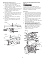
ADJUSTING THE 90° TABLE STOP (FIG. K)
1. Loosen the table lock knobs (1) and tilt
the table to the right.
2.
Loosen the nut (2) on the table stop bolt (3)
and lower the stop bolt as far as possible.
3. Tilt the table until it rests on the stop bolt.
4. Place a combination square (4) on the
table with the heel of the square against
the saw blade (5).
5. Adjust the tilt of the table left or right until
it is 90° to the blade. Make sure there is
no space between the square and the
blade. Tighten the table lock knobs.
6. Adjust the table stop bolt up until it
touches the table. Tighten the jam nut
down to the support bracket.
7. Loosen the lock knobs and see that the
table is resting on the stop bolt.
8. Check the square to make sure the table
is still square to the blade. If not, re-adjust
the stop bolt.
9. When the adjustment is accurate at 90°,
align the pointer (6) to 0° on the scale (7).
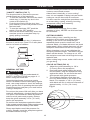
BLADE TENSION (FIG. L)
To avoid injury, turn the switch OFF and
disconnect the saw from the power source
before making any adjustments. NEVER make
tension adjustments with the machine running.
Blade tension was set at the factory. When
adjustment is needed please follow the
procedure below. The gauge (1) on the
bracket (2) at the rear of the upper
wheel indicates the proper tension for the
various blade widths.
1.
Set the blade tension gauge (1) to
correspond with the blade width, as shown.
2. Turn the blade tension knob (3) clockwise
to tighten the blade, counterclockwise
to loosen.
3. As you become familiar with the saw, you
may try to change the tension settings.
Fig. K
0
10
10
20
20
30
30
3
7
6
12
4
5
WARNING
!
NOTE: Changes in blade width and type of
material being cut will have an effect on the
blade tension. Too much or too little tension
could break the blade.
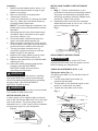
BLADE TRACKING (FIG. M)
To avoid injury, turn the switch OFF and
disconnect the saw from the power source
before making any adjustments. NEVER
make tracking adjustments with the
machine running.
Blade tracking was set at the factory. When
adjustment is needed please follow the
procedure below.
1. The blade (1) must be tensioned properly
before adjusting the tracking. (See
BLADE TENSION)
2. Open the upper cover.
3. Move the blade guides (2) and support
bearings (3) away from the blade,
if necessary.
4. Rotate the wheel (4) slowly forward by
hand, and check the position of the blade
on the wheel. The blade should remain
centered on the wheel as it turns.
5. If the blade moves toward the front of the
wheel, turn the tracking knob (5) on the
rear of the band saw clockwise. This tilts
the top of the wheel and moves the blade
toward the center.
6. If the blade moves toward the back edge,
turn the tracking knob counterclockwise,
moving the blade toward the center.
NOTE: Turn the tracking knob SLIGHTLY to
make blade tracking adjustments.
WARNING
!
Fig. L
12
14
18
2
1
3

16
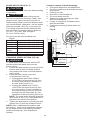
UPPER BLADE GUIDE ASSEMBLY (FIG. N)
To avoid injury, turn the switch OFF and
disconnect the saw from the power source
before making any adjmstments. NEVER
make adjustments with the machine running.
1. Loosen the wing nut (1) and the lock
knob (2), and hold the knob (3) to move
the blade guide assembly (4) to 1/8 in.
(3.2 mm) above the workpiece.
2. If necessary, rotate the assembly until the
guide blocks (5) are at (parallel) to the
blade (6). Tighten the lock knob.
UPPER BLADE GUIDES AND BLADE
SUPPORT BEARING (FIG. O, P)
The blade guard has been removed for clarity
of illustration. To avoid injury, never operate
the band saw without all guards in place and
in working order.
Fig. M
5
4
3
2
1
WARNING
!
Fig. N
5
6
4
2
1
3
To avoid injury, turn the switch OFF and
disconnect the saw from the power source
before making any adjustments. NEVER
make adjustments with the machine running.
NOTE: Make sure the blade is tensioned and
tracking properly. Adjust the blade guides and
support bearing after each blade tension and
tracking adjustment. When the upper blade
guides and support bearings are adjusted,
the lower guides and bearings should also
be adjusted.
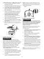
Blade guides (Fig. O)
Blade guides have been set at the factory but
should be checked.
1. Make sure the blade is tensioned and
tracking properly.
2. Loosen the front hex socket screws (1)
with a hex wrench supplied.
3. Move the guide blocks (2) as close to the
blade (3) as possible without pinching it.
4. Using a feeler gauge, make sure the
space between guide block and the blade
measured is 0.002 in. (0.05 mm, the
thickness of a dollar bill).
5. Tighten the hex socket screws.
6. Loosen the side thumb screw (4) by
turning counterclockwise.
7. Turn the rear knob (5) to move the blade
guide brackets in or out until the guide
blocks (2) are just behind the blade teeth.
8. Tighten the thumb screw.
Support bearing (Fig. P)
Support bearing has been set at the factory
but should be checked.
9. Loosen the knob (6).
10. Turning the rear knob (7), move the support
bearing (8) in or out until the bearing is
1/64 in. (0.4 mm) behind the blade.
11. Tighten the knob (6).
WARNING
!
WARNING
!
Fig. O
2
1
2
5
3
4

17
5. Loosen the side hex socket screw (4).
Move the guide block support bracket (6)
in or out until the blocks are just behind
the saw teeth. Tighten the screw. (Fig. R)
Support bearing
6. Loosen the bearing hex socket screw (7)
with the hex wrench.
7. Move the blade support bearing shaft (8)
in or out until the support bearing (9) is
1/64 in. (0.4 mm) behind the saw blade.
8. Tighten the bearing hex socket screw.
9. The back edge of the blade (3) should be
positioned 1/16 in. (1.6 mm) to 1/8 in.
(3.2 mm) from the right edge of the
support bearing (9), as shown.
PULLEY ALIGNMENT (FIG. S)
The pulley alignment has been adjusted
at the factory and shouldn’t require further
adjustment. If adjustments are required
or belt needs replacing, please follow
these procedures:
1. Place a straight edge in the front groove
of both pulleys, behind the blade wheel.
2. Turn the hex socket screw (1) in the
side of the motor pulley (2) to loosen the
pulley on the shaft.
3. Adjust the motor pulley in or out on the
motor shaft (3) to align the edges of the
two pulleys.
4. When aligned, tighten the hex socket
screw on the side of the motor pulley.
NOTE: This blade support bearing prevents
the blade from moving back too far and
damaging the saw teeth setting.
12. Check the lateral position of the support
bearing (8). The vertical back edge of the
blade (3) should overlap the front face of
the support bearing 1/16 in. (1.6 mm) to
1/8 in. (3.2 mm) to the left of the right
bearing edge, as shown.
LOWER BLADE GUIDES AND SUPPORT
BEARING (FIG. Q, R)
To avoid injury, turn the switch OFF and
disconnect the saw from the power source
before making any adjustments. NEVER
make adjustments with the machine running.
NOTE: Make sure the blade is tensioned and
tracking properly. The lower blade guides and
support bearings should always be adjusted
after the blade is tensioned, the tracking is
adjusted, and the upper blade guides and
upper support bearings are properly adjusted.
Blade guides
1. Loosen both front hex socket screws (1)
with a hex wrench.
2. Move the guide blocks (2) as close to the
sides of the blade (3) as possible without
pinching it.
3. Using the feeler gauge, measure the
spaces between the guide blocks and the
blade. Adjust to 0.002 in. (0.05 mm).
4. Tighten the hex socket screws. (Fig. Q)
Fig. P
8
6
7
8
3
WARNING
!
1
2
3
Fig. Q
Fig. R
3
9
2
78
4
6
Fig. S
13
2
3
2

18
OPERATION
BASIC SAW OPERATIONS
“ON/OFF” SWITCH (FIG. T)
The keyed switch is intended to prevent
unauthorized use of the band saw.
1. To turn the band saw ON insert the black
switch key (1) into the key slot in the
center of the switch (2).
2. Push the key rmly into the slot, then
push switch (2) to the ON position to start
the band saw.
3. To turn the band saw OFF push the
switch (2) to the OFF position.
4. Remove the black switch key, when the
saw has come to a complete stop, by
gently pulling it outward.
Remove the black switch key (1) whenever
the saw is not in use. Place it in a safe place
and out of reach of children.
GENERAL CUTTING
For your safety, read and understand all
SAFETY INSTRUCTIONS on pages 4 - 6
before using the band saw.
Operating band saws involves a certain
amount of hazard. Before attempting regular
work, use scrap lumber to check the settings,
and to get the feel of operating the band saw.
Read instructions and plan your work before
cutting a workpiece.
Do not turn the power ON until after you have
made all adjustments, checked that the guard
is in place, and turned the wheel by hand to
make sure all parts work properly. Always
keep the guide assembly 1/8 in. (3.2 mm)
above the workpiece.
Do not force the workpiece against the blade.
Light contact permits easier cutting and prevents
unwanted friction and heating of the blade.
Sharp saw blades need little pressure for
cutting. Steadily move the workpiece against
the blade without forcing it.
WARNING
!
Fig. T
2
1
WARNING
!
To avoid twisting the blade do not turn sharp
corners; saw around corners.
A band saw is basically a “curve-cutting”
saw. It is not capable of doing intricate inside
cutting as can be done with a scroll saw.
It is also used for straight line operations such
as crosscutting, ripping, mitering, beveling,
compound cutting, and resawing.
To avoid blade breakage, re or other
damage or injury, NEVER use this band saw
to cut metals.
CUTTING CURVES
When cutting curves, carefully turn the
workpiece so the blade may follow without
twisting. If the curve is so sharp that you
repeatedly back up and cut new kerf, use a
narrower blade, or a blade with more set (teeth
further apart). When a blade has more set, the
workpiece turns easier but the cut is rougher.
When changing a cut, do not withdraw the
workpiece from the blade. The blade may get
drawn off the wheels. To change a cut, turn
the workpiece and saw out through the scrap
material area.
When cutting long curves, make relief cuts as
you go along.
ClRCLE CUTTING (FIG. U)
1. Adjust the guide assembly to 1/8 in.
(3.2 mm) above the workpiece.
2. Use both hands while feeding the work
into the blade. Hold the workpiece rmly
against the table. Do not force the work
and operate with gentle pressure.
3. The smallest diameter circle that can
be cut is determined by the width of the
blade. For example, a 1/4 in. (6.4 mm)
wide blade will cut a minimum diameter of
approximately 1-1/2 in. (38.1 mm).
WARNING
!
Fig. U
1/2 in. D
1/8 in.
1 in. D 1-1/2 in. D 2 in. D 2-1/2 in. D
3/16 in. 1/4 in. 3/8 in. 1/2 in.
Minimum
Circle Diameter
Blade Width
(3.2 mm) (4.8 mm) (6.4 mm) (9.5 mm) (12.7 mm)
(12.7 mm) (25.4 mm) (38.1 mm) (50.8 mm) (63.5 mm)

19
Common causes of blade breakage:
● Poor guide alignment and adjustment.
● Forcing or twisting a wide blade around a
short radius.
● Feeding too fast.
● Dull teeth or not enough set.
● Too much blade tension.
● Setting top guide assembly too high
above the workpiece.
● Lumpy or improperly nished braze or
weld on the blade.
● Continuous running of blade when not
cutting.
BLADE SELECTION (FIG. V)
Blade teeth are sharp. Use care when handling
a saw blade.
For longest wear and best cutting results,
use the correct blade thickness, width, and
temper for the type of material you will cut.
When sawing small curves and delicate work,
use narrow blades. Otherwise, use the widest
blade as possible. (See Fig. U on page 18)
For cutting wood and similar materials with
this band saw, purchase blades in width up
to 1/2 in. (12.7 mm), and a length of
93-1/2 in. (2374.9 mm).
Do not cut metals with this band saw.
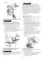
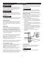
CHANGING SPEED SETTING (FIG. W)
To avoid injury, turn the power switch OFF
and disconnect the band saw from the
power source.
1. Loosen the belt tension by turning the belt
tension bolt (6) with a suitable wrench
and rotating the motor counterclockwise
until it stops.
2. Open the lower wheel cover and
re-position the V-belt (3).
● Changing the speed from 1630 to
2730 FPM: rst remove belt (3) from
the band saw pulley(4); reposition in
the saw pulley groove (1).
● Change the speed from 2730 to
1630 FPM: rst remove belt (3) from
the motor pulley (5) and reposition in
the motor pulley groove (2). Remove
the belt from the saw pulley (4) and
reposition in the saw pulley groove (2).
NOTE: The pulley belt is properly tensioned
when there is 1/2 in. (12.7 mm) deection if
pressed in the center of the pulleys.
3.
Tighten the belt tension by turning the belt
tension bolt (6) with the suitable wrench.
NOTE: After re-adjusting belt position and
belt tension, verify and re-adjust the settings
for the blade tension and tracking position,
guides and bearings. (See Adjustment
section)
CAUTION
!
CAUTION
!
Fig. V
Operation
Recommended Blade Width (Inches)
Cross Cutting
1/4, 3/8, 1/2 in. (6.4 ,9.5, 12.7 mm)
Mitering
1/4, 3/8, 1/2 in. (6.4 ,9.5, 12.7 mm)
Beveling
1/4, 3/8, 1/2 in. (6.4 ,9.5, 12.7 mm)
Compound
Cutting
1/4, 3/8, 1/2 in. (6.4 ,9.5, 12.7 mm)
Circle Cutting
See chart on page 18
Curve Cutting
1/8, 1/4 in. (3.2, 6.4 mm)
WARNING
!
4
53
2
1
4
5
1
2
MOTOR
6
Fig. W

20
INSTALLING A NEW BELT (FIG. X)
1. Open the lower wheel door.
2. Loosen the blade tension by turning the
blade tension lock knob (1).
3. Remove the blade from the lower blade
wheel.
4. Loosen and remove the hex head
bolt (2) and ange (3) on the lower
blade wheel.
5. Remove the lower blade wheel.
6. Turn the belt tension bolt (4) on the rear
of the saw housing with a suitable wrench
to loosen the v-belt tension.
7. Remove the v-belt (5).
8. Check the alignment of the two pulleys.
9. If the edges of the two pulleys are not
aligned, see “PULLEY ALINGMENT” in
ADJUSTMENT section.
10. Place the new v-belt on the saw pulley
and the motor pulley. See OPERATION
section “CHANGING SPEED SETTINGS”
on page 19 for proper belt placement.
11. When the pulley belt is positioned
properly, tighten the v-belt tension by
turning the belt tension handle.
NOTE: The pulley belt is properly tensioned
when there is a 1/2 in. (12.7 mm) deection
if pressed in the center of the pulleys.
12. Replace the blade wheel. Push the wheel
in rmly until it is touching the saw pulley.
Replace and tighten the ange and nut.
13. Reinstall the blade. (See “INSTALLING
BLADES” section on page 13)
14. Adjust the blade tension, tracking, the
upper and lower blade guides and
bearings before operating the band saw.
To avoid injury, the blade tension, tracking,
and upper and lower guides and bearings
must be properly adjusted before operating
the band saw. (See “ADJUSTMENT
INSTRUCTIONS” section)
WARNING
!
Fig. X 1
4
3
2
5
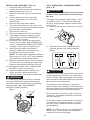
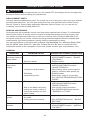
240 V OPERATION - CHANGING WIRES
(FIG. Y, Z)
To avoid injury, disconnect the motor from
power source outlet before reconnecting
the wire.
The band saw provided a dual voltage, 120 V
and 240 V, motor. To operate the band saw
at 240 V, single phase, please reconnect the
motor wires.
1. Remove the screw (1) and wire cover (2).
2. Reconnect the motor wires and power
wires as shown in the wiring diagram.
A qualied electrician should do the conversion,
or the machine can be taken to an Authorized
Service Center. When completed, the machine
must conform to the National Electric Code and
all local codes and ordinances.
The machine is converted by re-wiring the
motor for 240 volts, installing a 240 volt plug on
the power supply cord and replacing the switch
with one that is rated for 240 volt operation.
Be sure the 240 volt plug is only used in an
outlet plug. No adapter should be used with
the 240 volt plug.
In all cases, make certain that the receptacle
in question is properly grounded. If you are
not sure, have a qualied electrician check
the receptacle.
NOTE: The 240 volt plug is not supplied with
this product. Please check with a qualied
electrician for the correct plug.
WARNING
!
CAUTION
!
Fig. Y
Fig. Z
2
1
WIRING DIAGRAM
120 V
MOTOR
WHITE
YELLOW
GRAY
RED
BLACK
GREEN
BLACK
WHITE
YELLOW
GRAY
RED
BLACK
GREEN
BLACK
240 V
MOTOR
Page is loading ...
Page is loading ...
Page is loading ...
Page is loading ...
Page is loading ...
Page is loading ...
Page is loading ...
Page is loading ...
-
 1
1
-
 2
2
-
 3
3
-
 4
4
-
 5
5
-
 6
6
-
 7
7
-
 8
8
-
 9
9
-
 10
10
-
 11
11
-
 12
12
-
 13
13
-
 14
14
-
 15
15
-
 16
16
-
 17
17
-
 18
18
-
 19
19
-
 20
20
-
 21
21
-
 22
22
-
 23
23
-
 24
24
-
 25
25
-
 26
26
-
 27
27
-
 28
28


Porter-Cable PCB330BS User manual
- Category
- Power tools
- Type
- User manual
Ask a question and I''ll find the answer in the document
Finding information in a document is now easier with AI
Related papers
Other documents
-
Craftsman 137284630 Owner's manual
-
Wen 3959T User manual
-
King Canada KC-1401HD User manual
-
-
-
-
-
Hitachi CB 13F User manual
-
RIDGID BS14002 User manual
-