Page is loading ...

READ AND SAVE THESE INSTRUCTIONS
Address: 46101 Fremont Boulevard, Fremont, CA 94538
US Toll Free Number: 1-888-979-9889
www.deltabreez.com
TABLE OF CONTENTS
Package Contents 2
General Safety Information 3
Preparation 4
Assembly Instructions 5
New Construction 5
Existing Construction 6
Grille Installation 8
Operation 8
Care and Maintenance 9
Troubleshooting 10
Dimensions 11
11
Warranty 12
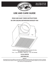
VENTILATION
FAN / LED LIGHT
MODEL 50F-LED/80F-LED
MFG MODEL
VFB050B4LED1 / VFB080B4LED1

2
1
2
3
PART DESCRIPTION QTY
▢
Fan Body 1
▣
Grille 1
▤
Duct Connector 1
PACKAGE CONTENTS

3
READ AND SAVE THESE INSTRUCTIONS
GENERAL SAFETY INFORMATION
CA si egatlov ylppus ecivres cirtcele eht taht erus ekaM .1
120V, 60Hz.
sa llew sa ,sedoc ytefas dna lacirtcele lacol lla wolloF .2
the National Electrical Code (NEC) and the Occupational
Safety and Health Act (OSH Act).
ro no gnikrow erofeb ecruos rewop eht tcennocsid syawlA .3
near the ventilating fan, motor or junction box.
toh ,esaerg ,lio ,segde prahs morf droc rewop eht tcetorP .4
surfaces, chemicals or other objects.
5. Do not kink the power cord.
6.
shown in Fig.A.
7. Provide suction parts with proper ventilation.
rewohs ro buthtab a revo esu rof detsiL LU si tinu sihT .8
when installed in a GFCI protected branch circuit.
WARNING
TO REDUCE THE RISK OF FIRE, ELECTRIC SHOCK, OR
INJURY TO PERSONS, OBSERVE THE FOLLOWING:
eht yb dednetni rennam eht ni ylno tinu siht esU .1
manufacturer. If you have questions, contact the
manufacturer.
ffo rewop eht hctiws ,tinu eht gninaelc ro gnicivres erofeB .2
at the service panel and lock the service disconnecting
means to prevent the power from being switched on
accidentally. When the service disconnecting means
cannot be locked, securely fasten a prominent warning
device, such as a tag, to the service panel.
yb enod eb tsum gniriw lacirtcele dna krow noitallatsnI .3
4.
burning equipment to prevent backdrafting. Follow the
heating equipment manufacturer’s guideline and safety
standards such as those published by the National Fire
Protection Association (NFPA), and the American Society
for Heating Refrigeration and Air Conditioning Engineers
(ASHRAE) and local code authorities.
ton od ,gniliec ro llaw eht otni gnillird ro gnittuc nehW .5
damage electrical wiring and other hidden utilities.
.sroodtuo eht ot detnev eb syawla tsum snaf detcuD .6
GENERAL SAFETY INFORMATION
tsum ti ,rewohs ro but a revo dellatsni eb ot si tinu siht fI .7
be marked as appropriate for the application and be
connected to a GFCI (Ground Fault Circuit lnterrupter) –
protected branch circuit.
lortnoc etats-dilos rehto yna htiw tinu siht esu ton oD .8
device. Solid-state controls may cause harmonic
distortion, which can cause a motor humming noise.
a morf dehcaer eb nac ti erehw hctiws a ecalp REVEN .9
tub or shower.
a ot detalusni yllamreht gniliec a ni dellatsni eb ot toN .01
value greater than R40. (This is required for installation
in Canada only).
CAUTION
tsuahxe ot esu ton oD .ylno esu gnitalitnev lareneg roF .1
hazardous or explosive materials and vapors.
)B.giF( .saera gnikooc ni esu rof toN .2
gnidnuorg eht ot tcennoc ylreporp tsum tcudorp sihT .3
conductor of the supply circuit.
ta naf eht llatsni ,snosrep ot yrujni fo ksir eht ecuder oT .4
4
5
°
Cooking area
4
5°
Do not install above or
inside this area
Cooking
Equipment
floor
Fig. B
Turning angle too large Duct shrink
ydob eht raen woblEswoble ynam ooT
Body
Fig. A

4
PREPARATION
Tools Required for Assembly (not included): Hammer,
Flathead Screwdriver, Wire Nuts, Nails, Duct Tape,
Phillips Head Screwdriver, Utility Knife
Helpful Tools (not included): Electric Drill, Drill Bits
WARNING: Turn off electricity at breaker box
before beginning installation.
Carefully remove unit from carton.
Check area above installation location to be sure that
wiring can run to the planned location and that duct
proper ventilation.
Inspect duct work and wiring before proceeding with
installation.
Before installation, provide inspection and future
maintenance access at a location that will not
interfere with installation work.
You may need the help of a second person to install
this fan: one person on the attic side and one on the
room side.
Note: Installations may vary depending on how the
previous bath fan was installed. Supplies necessary
for the installation of your bath fan are not all included.
However, most are available at your local home
improvement or hardware store.
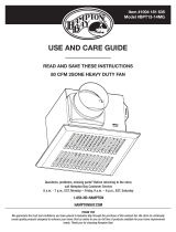
WIRING DIAGRAM
DIMENSION REQUIREMENTS
LIGHT SWITCH
FAN SWITCH
OFF
ON
ON
OFF
ON/OFF SWITCH
(purchase separately)
SWITCH BOX
120 VAC
LINE IN
WIRING
PLATE
BLACK
WHITE
GROUND
RED
LIGHT
SWITCH
FAN
SWITCH
WIRE NUT
(NOT INCLUDED)
WIRE NUT
(NOT INCLUDED)
Ceiling
Opening (L)
Ceiling
Opening (W)
Ceiling
Opening (H)
7 1/2 in. 7 1/4 in. 5 3/4 in.
Proper insulation around the fan to minimize building
heat loss and gain. 4” circular duct is recommended
for installation. The ducting from this fan to the
outside of the duilding has a strong effect on the
air flow, noise and energy use of the fan. Use the
shortest, straightest duct routing possible for best
performance, and avoid installing the fan with
smaller ducts than recommended. Insulation around
the ducts can reduce energy loss and inhibit mold
growth. Fans installed with existing ducts may not
The fan will operate most efficiently when located
where the shortest possible duct run and minimum
of elbows will be needed.
Use a roof cap or wall cap that has a built-in damper
to reduce backdrafts.
External timer/dimmer switch can be used please
contact Delta Breez customer service and consult
with a licensed electrician for compatibility.
Roof cap
(with built-in
damper)
Seal gap
around
housing
Caulk termination
to duct
Fan housing
Short piece of flexible
duct helps alignment
and absorbs sound
or
Wall cap
(with built-in
damper)
Wall cap
(with built-in
damper)
2~3 ft straight run
before elbow

5
ASSEMBLY INSTRUCTIONS
NEW CONSTRUCTION
Turn off power source. Review all safety precautions.
1. Attach the Duct Connector
▤
to the Fan Body
▢
2. Remove the wiring box cover from the Fan Body
▢
.
Remove the wiring knockout from the wiring box
3. Place the Fan Body
▢
next to a ceiling joist
or wall stud. The fan body should be level and
perpendicular to the joist or stud.
4. Mount the Fan Body
▢
to the joist or stud using
nails (not included) where indicated.
5. Pull the wire through the hole and into the junction
box(not included), secure 120VAC house wiring
from the wall diagram on page4. 14AWG is the
smallest conductor that shall be used for branch-
circuit wiring.
Push the wires back through the hole. Reattach the
wiring box cover.
1
2
3
1
1
Joist or
1
3
Joist or
wall stud
1
4
5

6
ASSEMBLY INSTRUCTIONS
6. Install a circular 4 in. duct (not included) and secure
it with duct tape or clamps (neither included). Finish
ceiling work. The ceiling hole should be aligned with
the edge of the Fan Body
▢
.
Turn off power source. Review all safety precautions.
1. Remove existing fan.
2. Measure the opening to ensure it is large enough to
accommodate the new Fan Body(7 1/2in. x 7 1/4in.).
the joist.
3. If this fan is not replacing an old fan, be sure to cut
a 7 1/2in. x 7 1/4in. opening for the Fan Body
▢
.
with the joist for installation from below.
4. Attach the Duct Connector
▤
to the Fan Body
▢
.
Ceiling
4 in. Duct
Duct tape
or clamp
1
6
1
2
9.4"
9.4"
7 1/ 2 in.
7 1/4 in.
3
1
3
4
EXISTING CONSTRUCTION

7
ASSEMBLY INSTRUCTIONS
5. Remove the wiring box cover from the Fan Body
▢
.
Remove the wiring knockout from the wiring box
6. Remove the three screws that hold the fan motor
assembly in place. Remove the fan motor assembly
from the Fan Body
▢
. Unplug fan connector.
7. Pull the wire through the hole and into the junction
box(not included), secure 120VAC house wiring
from the wall diagram on page4. 14AWG is the
smallest conductor that shall be used for branch-
circuit wiring.
Push the wires back through the hole. Reattach the
wiring box cover.
8. Install a circular 4 in. duct (not included) and secure
it with duct tape or clamps (neither included).
Mount the Fan Body
▢
to the joist or stud using
nails (not included) were indicated.
9. Plug the fan assembly back into the Fan Body
▢
.
Reattach the fan assembly using the three screws.
Plug fan connector.
1
1
1
1
5
6
7
8
9

8
GRILLE INSTALLATION
FAN / LED LIGHT OPERATION
Insert the LED light connector into the fan body.
Pinch the mounting springs on the Grille
▣
, and insert
them into the narrow rectangular slots inside the fan.
Push the Grille
▣
up toward the ceiling.
installation.
Operation
Fan mode: Turn the Fan switch to operate ON/OFF of
Fan function.
Light mode: Turn the Light switch to operate ON/OFF
of LED lighting function.
2

9
See safety information before proceeding. Routine maintenance should be done at least once a year.
• Never use solvents, thinner or harsh chemicals when cleaning the fan.
• Do not allow water to enter the motor.
• Do not immerse metal parts in water.
• Do not immerse resin parts in water over 140º Fahrenheit.
• Do not immerse LED module in water.
Turn off power source. Review all safety precautions.
CARE AND MAINTENANCE
1. To remove grille
▣
, squeeze springs and pull down.
2. Wash and clean the grille
▣
in a sink and dry with a
cloth.
3. Remove dust and dirt from the fan body
▢
with a vacuum
cleaner.
4. Dampen cloth with dust detergent and wipe the fan body
▢
. Then wipe dry with a clean cloth.
5. Replace grille
▣
back onto fan body
▢
6. Turn on power source to operate fan again.
2
1
2
2
1
Vacuum
cleaner
1
2
3
4
5

10
TROUBLESHOOTING
PROBLEM POSSIBLE CAUSE CORRECTIVE ACTION
The fan is not turning on 1. Power off
2. Faulty switch
3. Faulty wire connection
1. Make sure power supply is on.
2. Test or replace switch.
3. Check wire in switch box.
The fan seems louder
than it should
1. CFM too great
2. Damper not working
properly or damaged
3. Bend in duct too close
to fan discharge
4. Fan discharge
duct
5. Fan body not securely
attached
1. Be sure the CFM rating on the fan matches the
size of your room.
2. Check damper to ensure it is opening and closing
properly. If the damper has become damaged,
please call Customer Service.
3. Be sure you do not have any sharp bends in duct
closer than 18 in. to the fan discharge.
4. Use recommended size ducting to reduce fan
noise.
5. Be sure the fan is securely attached to your ceiling
joists.
The fan is not clearing
the room
1.
airfow within room
2.
1. Be sure a door or window is slightly ajar or opened
2. Be sure the CFM rating on the fan matches the
requirements for your room size.
The light is not turning
on
1. Power off
2. Faulty switvh
3. Faulty wire connection
1. Male sure power supply is on.
2. Test or replace switch.
3. Check wire in switch box.

11
DIMENSIONS
PRODUCT SPECIFICATIONS
UNIT: INCH
SPECIFICATIONS
Model No.
Frequency
(Hz)
Fan Power
@0.1”SP(W)
Air Flow
@0.1”(CFM)
Weight
(lb.)
LED light
spec.
50F-LED /
VFB050B4LED1
4.8
,stta 0.31 W
850Lumens,
2700K
80F-LED /
VFB080B4LED1
4.8
Note
Single
Speed
Single
Speed
Max Current
(Amps)
0.22
0.28
,stta 0.31 W
850Lumens,
2700K
120
120
Voltage
(V)
60
60
50
80
5.0
11.3

12
WARRANTY
DELTA ELECTRONICS THREE YEAR LIMITED WARRANTY
Delta Electronics Inc. (“Delta Electronics”) warrants to the original consumer purchaser in the USA that the Breez
ventilation fan products will be free from defects in material or workmanship. This warranty is limited to three (3)
years from the original date of purchase.
Limitations and Exclusions
1. During the warranty period, a replacement for any defective product will be supplied free of charge for installation
by the consumer. The warranty provided herein does not cover charges for labor or other costs incurred in the
troubleshooting, repair, removal, and installation service.
2. All returns of defective parts or products must include the product model number, and must be made through an
authorized Delta Electronics distributor. Authorized returns must be shipped prepaid. Repaired or replacement
products will be shipped by Delta Electronics F.O.B. shipping point.
3. Delta Electronics shall not be liable for any indirect, incidental, consequential, punitive, or special damages
arising out of or in connection with products use or performance, regardless of the form of action whether in
contract, tort (including negligence), strict product liability or otherwise.
4.
5. The warranty does not cover if user does not comply with manufacturer’s installation manual.
6. To qualify for warranty service, you must notify Delta Electronics at the address or telephone number below.
7. Delta Electronics shall have no liability to the original owner-user with respect to any defect caused by abuse,
misuse, neglect, improper transportation or storage, improper testing, improper installation, improper operation,
accident of products or parts thereof, or unusual deterioration or degradation of products or parts thereof due to
Address: 46101 Fremont Boulevard, Fremont, CA 94538
US Toll Free Number: 1-888-979-9889
www.deltabreez.com
/