Cooper Tools Quackenbush 158QGDA User manual
- Category
- Power drills
- Type
- User manual

1
Operation & Service Manual
823159 2/01
15QGDA, 15QGDAB, 158QGDA,
158QGDAB, 158QGDAV & 158QGDABV
S150B & S275B POSITIVE FEED DRILLS
NORTH AMERICA EUROPE
CooperTools
P.O. Box 1410
Lexington, SC 29071
Cooper Power Tools GmbH & Co.
Postfach 30
D-73461 Westhausen

2
Safety Recommendations
For your safety and the safety of others, read and understand
the safety recommendations and operating instructions before
operating any drill motor.
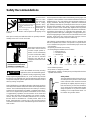
Always wear protective equipment:
For additional information on eye and face protection, refer to
Federal OSHA Regulations, 29 Code of Federal Regulations, Sec-
tion 1910.133., Eye and Face Protection, and American National
Standards Institute, ANSI Z87.1, Occupational and Educational Eye
and Face Protection. Z87.1 is available from the American National
Standards Institute, Inc. 11 West 42nd Street, New York, NY 10036.
Hearing protectors are required in high noise areas, 85 dBA or
greater. The operation of other tools and equipment in the area,
reflective surfaces, process noises and resonant structures can
substantially contribute to, and increase the noise level in the area.
For additional information on hearing protection, refer to Federal
OSHA Regulations, 29 Code of Federal Regulations, Section 1910.95,
Occupational Noise Exposure, and American National Standards
Institute, ANSI S12.6, Hearing Protectors.
Follow good machine shop prac-
tices. Rotating shafts and moving
components entangle and entrap,
and may result in serious injuries.
Never wear long hair, loose-
fitting clothes, gloves, ties, or jew-
elry when working with or near a
drill of any type.
Quackenbush drills are designed
to operate on 90psig (6.2 bar)
maximum air pressure using the
proper hose. Excessive air pres-
sure increases the loads and
stresses on tool parts and drills,
and may result in breakage. The installation of a filter-regulator-
lubricator in the air supply line ahead of the tool is highly recom-
mended.
CAUTION!
Personal hearing protection is
recommended when operating
or working near this tool.
WARNING!
Impact resistant eye protection
must be worn while operating
or working near this tool.
!
Do not wear loose fitting clothes,
long hair, gloves, ties or jewelry.
WARNING
WARNING
!
Wear respirator where
necessary.
• Before the tool is connected to the air supply, the throttle should
be checked for proper operation (i.e., throttle valve moves freely
and returns to closed position).
• Before removing a tool from service or changing drill bits, make
sure the air line is shut off and drained of air. This will prevent the
tool from operating if the throttle is accidently engaged.
• Cutting tools used with these drill motors are sharp. Handle them
carefully to avoid injury.
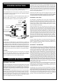
Before mounting any positive feed drill, check
the lock screws in the tooling fixture and drill
bushing. Make sure both are in good condi-
tion and securely tightened.
Positive feed drills can exert high torques and high thrust loads. If
failure of the lock screws or drill bushing occurs, the drill may
suddenly spin and back away from the drill fixture.
Always remove chuck key or drill drift before operating tool.
Drilling or other use of this tool may produce hazardous fumes and/
or dust. To avoid adverse health effects utilize adequate ventilation
and/or a respirator. Read the material safety data sheet of any
cutting fluids or materials involved in the drilling process.
Some non-ferrus metal chips (or dusts) are
combustible. Examples: Aluminum, magne-
sium, Titanium, and Zirconium. See the
material safety data sheets for combustibility of materials drilled.
Never collect spark generating material with combustible material.
Examples: Collecting both steel and aluminum or steel and titanium.
Tool Nose
Standard Threaded
Drill Bushing
Lock Screws
Tooling Fixture
CAUTION
!
CAUTION!
CAUTION
!

3
Safety Recommendations
CAUTION!
Slip and fall hazard.
Lubricant and coolant systems must
be properly maintained to avoid
leakage.
Hoses must be organized and care
taken to avoid tripping.
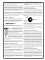
Extension Neutral Flexion Radial Deviation Neutral Ulnar Deviation
Avoid Avoid Avoid
OK Avoid OK
CAUTION!
Quackenbush
drills are often
used with lubri-
cant or cooling
systems which
must be properly
maintained to
avoid leakage.
Failure to do so can result in serious injuries from slipping on oily
surfaces.
Nose pieces usually used with these drills are generally slotted for
visibility and access to chuck and cutter.
Keep fingers and hands away
from slots in the tool nose at
all times. Rapid spindle re-
traction occurs automatically
on most models after drilling
cycle and can be activated
manually even with the air
supply disconnected on some
models.
Due to the multitude and variety of tooling
applications, the User's Methods Engineer-
ing, Standard Tooling Engineering, and/or
Safety Engineering Departments, etc., must consider any hazards
that may be associated with each specific application of this product
and provide adequate operator protection from inadvertent contact
with any moving components.
Some individuals are susceptible to disorders of the hands and arms
when exposed to vibration and/or tasks which involve repetitive work
motions. Those individuals predisposed to vasculatory or circulatory
problems may be particularly susceptible. Cumulative trauma disor-
ders such as carpal tunnel syndrome and tendinitis can be caused
or aggravated by repetitious, forceful exertions of the hands and
arms. These disorders develop gradually over periods of weeks,
months, and years. Tasks should be performed in such a manner
that the wrists are maintained in a neutral position, which is not
flexed, hyperextended, or turned side to side. Stressful postures
should be avoided and can be controlled through tool selection and
work location.
Any tool operator should be aware of the following warning signs and
symptoms so that a problem can be addressed before it becomes a
debilitating injury. Any user suffering from prolonged symptoms of
tingling, numbness, blanching of fingers, clumsiness or weakened
grip, inability to hold objects, nocturnal pain in the hand, or any other
disorder of the shoulders, arms, wrists, or fingers should notify their
employer so that a review of what steps might be taken to prevent
further occurances. These steps might include but are not limited to,
repositioning the workpiece or redesigning the workstation, reas-
signing tool users to other jobs, rotating jobs, changing worker pace,
and/or changing the type of tool used so as to minimize stress on the
operator. Some tasks may require more than one type of tool to
obtain the optimum operator/ tool/ task relationship.
The following recommendations will help reduce or moderate the
effects of repetitive work motions. The operator of any drill should:
• Use a minimum hand grip force consistent with proper control and
safe operation
• Keep body and hands warm and dry
• Avoid anything that inhibits blood circulation
— Smoking Tobacco
— Cold Temperatures
— Certain Drugs
• Avoid awkward postures
• Keep wrists as straight as possible
• Interrupt work, activities, or rotate jobs to provide periods free from
repetitive work motions.
Safety Labels
The safety labels found on these tools are an
essential part of this product. Labels should
not be removed. Labels should be checked
periodically for legibility. Replace safety la-
bels when missing or when the information
can no longer be read. Safety labels should
always be placed on any tool nose before
installing on tool. Replacement labels can
be ordered using number below.
Keep hands and fingers away
from slot in tool nose when
handling or operating tool.
WARNING
!
202657-3

4
OPERATING INSTRUCTIONS
The 15 & 158-150 & 275 are designed to operate on 90 psig air pressure
using a 3/8" I.D. hose up to 8' in length. If additional length is required, a
1/2" I.D. or larger hose should be connected to the 3/8" hose.
When the B throttle valve is turned to the on position, the drill and feed
cycle will begin. At the end of the feed stroke, the spindle will automati-
cally return to its starting position.
The tool's starting position is set by the adjustment plug located in the
spindle. The A "T" wrench 614190, is used to make this adjustment.
The tool's forward stroke is set by the C stop adjustment collar.
LUBRICATION
An automatic in-line filter-lubricator is recommended as it increases tool
life and keeps the tool in sustained operation. The in-line lubricator should
be regularly checked and filled with a good grade of 10W machine oil.
Proper adjustment of the in-line lubricator is performed by placing a sheet
of paper next to the exhaust ports and holding the throttle open approxi-
mately 30 seconds. The lubricator is properly set when a very light stain
of oil collects on the paper. Excessive amounts of oil should be avoided .
STORAGE
In the event that it becomes necessary to store the tool for an extended
period of time (overnight, weekend, etc.), it should receive a generous
amount of lubrication at that time and again when returned to service.
The tool should be stored in a clean and dry environment.
SERVICE INSTRUCTIONS
DISASSEMBLY—DRILL HEAD
To remove the drill head, remove the air line and clamp the cross shaft
housing in a soft-jawed vise. Unscrew (the #15 power unit has left-hand
threads) and remove the power unit. On piggyback units, the gear hous-
ing should be unscrewed from the drill head at this time. Disassembly
instructions for the gear housing are shown on the pages for the respec-
tive gear housing.
Unscrew the tool nose (left-hand threads), the chuck, and chuck adaptor,
621992, being careful not to damage the extension spindle. This will al-
low the bearing retainer 619692, to be removed (left-hand threads). NOTE:
As there is spring pressure against this part, care should betaken to avoid
losing associated parts. The cylinder 619691, and the piston 617034,
may now be slipped off the front of the shaft housing.
Removing the three screws 617331, and keys 863365, will allow the stop
adjustment collar to be unscrewed (left-hand threads). The return stop
617327, and pawls 619684, will allow the stop collar to be slipped off the
shaft housing. This allows the half-nuts to be removed. Unscrewing the
shaft housing will allow the lead screw with attached components to be
removed. Remove the retainer ring 843791, and press the lead screw
driver out of the gearbody 619117.
Remove the two retainer rings, and the two plugs from the cross shaft
housing. Press the cross shaft out of the side with the larger opening.
Using good standard disassembly procedures, the various assemblies
can be broken down for inspection and replacement of worn parts.
REASSEMBLY—DRILL HEAD
The drill head is reassembled in the reverse order of disassembly. All
parts should be thoroughly cleaned and inspected for damage or wear.
Damaged or worn parts should be replaced. Bearings which feel rough or
have excessive endplay should be replaced. As the drill head is reas-
sembled, apply a generous amount of "Lubriplate 907" grease, or equiva-
lent, to all the gears and bearings.
During reassembly of the cross shaft, place the worm wheel over the
long end of the cross shaft with the hub covering the hexagon portion of
the shaft. Place the worm wheel spacer over the shaft with the slot aligned
with the pin hole and insert the pin. Apply grease to the holes in the cross
shaft and install the steel balls. Holding the cross shaft with the worm
wheel to the right of the clutch, press the clutch spring over the hub of the
worm wheel, engaging the steel balls with the holes in the clutch spring.
NOTE: The clutch spring must wrap on the hub away from you with re-
spect to the holes in the spring. NOTE: Wrapping the spring in the oppo-
site direction will decrease the holding power of the clutch. When install-
ing the pinion and shaft assembly, do not press on the pinion and shaft
619119.
Insert the retainer ring 844975, in the gear body with the open section
toward the pinion 619119, for clearance of the pinion. "Lubriplate 907"
grease, or equivalent, should be packed in and around the lead screw to
aid in cushioning the retract cycle.
DISASSEMBLY—#15 POWER UNIT
To disassemble the gear train on the 160 RPM and 250 RPM power
units, clamp the motor housing lightly in a soft-jawed vise. Using a wrench
on the flats of the rear gear case 613733, unscrew it from the motor
housing. The first reduction gear spider will remain with the motor and
can be slipped out at this time. Clamp the flats of the rear gear case
lightly in the vise, and with a suitable wrench, unscrew the front gear case
613361 (left-hand threads). The second reduction gear spider 613587,
may now be removed from the front of the rear gear case. Clamp the flats
of the front gear case 613361, lightly in the vise and with a strap wrench,
unscrew the adapter 613550 (left-hand threads). Rest the rear face of the
adapter on the vise jaws and tap the third reduction spider 613553, out of
the spider bearing 843615. The idler gears may be removed from the
three gear spiders by removing the spider bearing with a bearing puller
and driving the idler gear pins out the rear of the spiders. Pinion gear
864239, which is used in the 250 RPM gear train, can then be removed
from the first reduction spider.
To disassemble the gear train on the 400 RPM, 800 RPM, and the 1400
RPM power units, clamp the motor housing lightly in a soft-jawed vise
and unscrew the gear case 613733. The first reduction spider may now
be slipped off the front of the motor.
Clamp the gear case in the vise and using a strap wrench, unscrew the
adapter 613544 (left-hand threads). Rest the rear face of the adapter on
the vise jaws and tap the second reduction spider out of the bearing
843615. After removing the spider bearing with a suitable bearing puller,
the idler gears may be removed by driving the idler gear pins out the rear
of the two spiders. Pinion gear 864239, which is used in the 1400 RPM
gear train, can then be removed from the first reduction spider.
A
C
ARROW INDICATES
CLOCKWISE
ROTATION
B
A
C
B
Turn wrench
clockwise
to raise spindle
Turn wrench
clockwise
to raise spindle
Turn to on
position to start
drilling operation
Turn to on
position to start
drilling operation
Raise and turn sleeve
counterclockwise
to increase stroke
Raise and turn sleeve
counterclockwise
to increase stroke

5
.0015" (.038mm)
Clearance
The gear train on the 2000 RPM and 3000 RPM power units is disas-
sembled by unscrewing the gear case 611534, from the motor housing.
Press the spider out of the rear of the gear case.
To remove the motor unit from the motor housing, hold the rotor shaft in
a soft-jawed vise and slip the motor unit out of the motor housing. Using
a soft-faced mallet, tap the rotor out of the front rotor bearing 844772.
The front bearing plate 864235, cylinder 864236, and four rotor blades
864234, may now be removed. Remove the rotor bearing retainer 812231,
and the rotor spacers from the rear of the rotor. Rest the front face of the
rear bearing plate 864232, on top of the vise jaws and with a suitable
driver, tap the rotor out of the rear rotor bearing 847095.
To disassemble the motor housing, remove the throttle ring retainer
613059. This will allow the throttle ring 613263, to be removed. Unscrew
the throttle valve cap 613060, and remove the throttle valve spring 613058,
throttle valve ball 844077, and throttle pin 613062, will allow the air inlet
screen 613066, to be removed for inspection and cleaning.
REASSEMBLY—#15 POWER UNIT
The power unit is reassembled in the reverse order of disassembly. All
parts should be thoroughly cleaned and inspected for damage or wear.
Damaged or worn parts should be replaced. Bearings which feel rough or
have excessive endplay should be replaced. Rotor blades which mea-
sure less than 7/32" (5.6mm) at either end should be replaced.
When assembling the motor, a clearance of .0015" desired between the
front face of the rear bearing plate and the rear face of the rotor.
If the rotor rubs the face of the rear bearing
plate, it indicates that the rotor collar is too
short and must be replaced. If clearance is
more than .0015", sand the square face of
the rotor collar until the desired clearance is obtained. Af-
ter the rotor collar has been fitted, install rotor spacers
between the retainer ring and the rear rotor bearing to keep
the bearing tight against the rotor collar.
As the gear train is assembled, apply a generous amount
of NLGI 2-EP grease or equivalent to all of the gears, gear
case teeth, gear spider, and bearings. On the triple reduc-
tion gear train, be sure that the notch in the ring gear
864329, is aligned with the ring gear pin in the front gear
case. As the gear train is assembled to the motor and
motor housing, make sure that the teeth on the rotor mesh properly with
those in the gear spider.
After the power unit is assembled, place a few drops of 10W machine oil
in the air inlet bushing before attaching the air hose This will insure im-
mediate lubrication of all parts as soon as the air is applied.
DISASSEMBLY—#158 STRAIGHT POWER UNIT
Clamp the power unit in a vertical position in a soft-jawed vise on the flats
of the motor housing 613275. Unscrew and remove the drill head adapter
617113. This will allow the internal gear 613285, to be unscrewed. The
planet cage and attached components may now be removed from the
rear of the internal gear.
On power units equipped with a double reduction, the internal gear and
housing 617369, may now be unscrewed from the motor housing. The
planet cage and attached components may now be removed from the
rear of the internal gear and housing.
To remove the motor unit invert the tool and loosen the handle nut 613283,
and remove the handle assembly. The complete motor can now be gen-
tly slipped out of the rear of the motor housing. Clamp the rotor shaft
lightly in the vise and unscrew the governor assembly (left-hand threads).
This will allow the rear bearing plate 613241, cylinder 613225, rotor 613234,
and rotor blades to be removed.
On units equipped with the pinion gear 617609, it will have to be un-
screwed before the rotor shaft can be removed from the front rotor bear-
ing. When removing the bearing retainer nut 613294, remember that it
has left-hand threads.
To disassemble the handle, remove the retainer ring 812231, and gently
push the throttle valve out of the bushing.
REASSEMBLY—#158 STRAIGHT POWER UNIT
The power unit is reassembled in the reverse order of disassembly. Wash
all parts thoroughly in a solvent and inspect for wear or damage before
reassembly. Bearings which show excessive looseness or roughness
should be replaced. During reassembly, all parts should receive a gener-
ous coating of NLGI 2-EP grease or equivalent. If rotor blades are worn
as much as 1/16" below the rotor surface, they should be replaced. NOTE:
The beveled edge of the blade is the trailing edge. The rotor 613234, and
the cylinder 613225, should have the "R" to the rear to insure correct
rotation.
When installing the sleeve 613242, the exhaust holes should be to the
rear of the unit. As the internal gear and components are assembled, the
tang end of the planet pins must be toward the front of the planet cage so
the planet cage washer will lock then in place.
After the tool is assembled, place a few drops of 10W machine oil in the
air inlet before attaching the air hose. This will insure immediate lubrica-
tion of all parts as soon as the air is applied.
DISASSEMBLY—#158 PIGGYBACK POWER UNIT
To disassemble the motor unit, clamp it in a vertical position in a soft-
jawed vise on the flats of the motor housing 613275, and unscrew the
internal gear 613285, from the housing. The planet cage 613284, with
attached components can be removed through the rear of the internal
gear. Using a suitable bearing puller, the rear planet bearing 613281, can
be removed. Clamp the planet cage in a vise and unscrew the motor gear
(left-hand threads), and remove the front planet bearing 864471, and
planet cage washer 613278. This will allow the planet pins 613279, and
planet wheels 613280, to be removed for inspection. To remove the mo-
tor unit, invert the tool, loosen the handle nut 613283, and remove the
handle assembly 611233. The complete motor can now be gently slipped
out through the rear of the motor housing. Clamp the exposed end of the
rotor shaft lightly in a soft-jawed vise and unscrew the governor (left hand
threads). NOTE: The governor should not be disassembled as it may be
ordered as a subassembly only. The rear bearing plate 613241, cylinder
613225, rotor 613234, and rotor blades can now be removed. Remove
the rotor shaft 843274. When removing the rotor bearing retainer 613294,
from the front bearing plate, remember that it has LEFT-HAND THREADS.
To disassemble the handle, remove the snap ring 812231 and gently
push the throttle valve out of the bushing. Unscrew the swivel nut for
cleaning and inspection of the screen.
REASSEMBLY—#158 PIGGYBACK POWER UNIT
The power unit is reassembled in the reverse order of disassembly. Wash
all parts thoroughly in a solvent and inspect for wear and damage before
reassembly. During reassembly, all parts should receive a generous coat-
ing of NLGI 2-EP grease or equivalent. If rotor blades are worn as much
1/16" below the rotor surface, they should be replaced. NOTE: The bev-
eled edge of the blade is the trailing edge. The rotor 613234, and the
cylinder 613225, should have the "L" to the rear to insure correct rotation.
As the internal gear and components are reassembled, the tang end of
the planet pins must be toward the front of the planet cage so the planet
cage washer will lock them in place.
Must be replaced if
7/32" (5.6mm) or less
at either end.

6
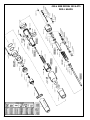
#15 & #158 MODEL 150 & 275
DRILL HEADS

7
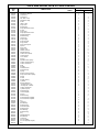
PART
NO.
614190
614927
614928
614929
614930
617034
617325
617326
617327
617328
617331
617333
617334
617337
619016
619117
619118
619119
619120
619123
619130
619141
619150
619154
619162
619167
619198
619199
619205
619300
619401
619663
619666
619667
619670
619675
619677
619678
619680
619681
619684
619685
619691
619692
619702
619703
619945
619949
619950
621992
627332
627333
627334
627335
812165
842086
8425l7
843791
844265
844568
844833
844975
863365
863459
863582
867388
882209
882407
884125
NAME OF PART
Adjustment Wrench
Thrust Rod
Thrust Rod
3/8" DriII Chuck
Adjustment Plug
Piston
Index Collar
Stop Collar
Return Stop
Stop Adjustment Collar
Screw
Stop Collar
Stop Adjustment Collar
Spring Separator
Retainer Ring
Gear Body
Plug (Large)
Pinion & Shaft
Plug (Small)
Spur Gear Spacer
Spacer
Spur Gear
Helical Gear
Helical Gear Pin
Needle Bearing
Grease Seal (Front)
Clutch Spring
Cross Shaft
Spacer
Spindle Return Spring
Lead Screw Driver Key
Lead Screw Driver
Pawl
Plunger
Thrust Washer
Shaft Housing
Spring
Retract Cushion Spring
Stop Collar Return Spring
Spring
Screw
Plunger Spring
CyIinder
Bearing Retainer
"O"-Ring 2/16'' x 2/4''
''O"-Ring 1/8" x 13/16"
Lead Screw Driver
Cylinder Spacer
Shaft Housing
Chuck Adapter
Spacer
Retainer Ring
S150 Extension Spindle
S275 Extension Spindle
Pin
Gear Key
BalI Bearing
Retainer Ring
Steel BaII (1/8")
Retainer Ring
Ball Bearing
Retainer Ring
Key
Needle Bearing
BaII Bearing
Clutch Pin
Alr Line Fitting
Air Line (Specify Length)
Pin
MODEL S150
1
1
-
1
1
1
1
1
1
1
3
-
-
1
1
1
1
1
1
1
1
1
2
2
2
1
1
1
1
1
2
1
2
2
1
1
2
1
1
1
1
2
1
1
1
1
-
-
-
1
1
2
1
-
2
2
2
2
5
2
1
2
3
1
2
2
1
1
-
S275
1
-
1
1
1
1
1
-
1
-
3
1
1
1
1
1
1
1
1
1
1
1
2
2
2
1
1
1
1
1
2
-
2
2
1
-
2
1
1
1
1
2
1
1
1
1
1
1
1
1
1
2
-
1
2
2
2
2
5
2
1
2
3
1
2
2
1
1
2
QUANITY
#15 & #158 MODEL 150 & 275 DRILL HEADS

8
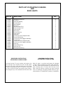
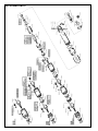
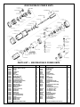
#15 PIGGYBACK GEARING & DRIVE SHAFT

9
PART NO.
612928
612975
612976
613312
619145
619156
619157
619212
619213
619214
619216
619217
619218
619293
619309
619536
619650
619674
619901
842086
843791
844656
847022
QTY .
4
4
2
1
1
1
1
1
1
1
1
1
2
1
1
1
2
1
1
1
1
2
1
NAME OF PART
Bearing Retainer Ring
Grip Ring
Idler Gear Bearing
Grease Fltting
Motor Adapter
Worm Pin
Worm Retainer Ring
Gear Housing Cover
Gear Housing
Motor Gear
Drive Shaft Gear
Gear Spacer
Idler Gear
S275 Drive Shaft (Straight Models)
Drive Shaft Bearing
S275 Drive Shaft (Piggyback Models)
Cover Screw
S150 Drive Shaft (Straight Models)
S150 Drive Shaft (Piggyback Models)
Gear Key
Gear Retainer Ring
Idler Gear Pin
Bearing Retainer Ring
PARTS LIST #15 PIGGYBACK GEARING
AND
DRIVE SHAFTS
DISASSEMBLY INSTRUCTIONS
#15 PIGGYBACK GEAR HOUSING
Unscrew the two (2) cover screws and remove the
gear housing cover. Remove the two (2) idler gears
and press thc drive shaft assembly out of the gear
housing, Removing the two (2) retainer rings from
the drive shaft will allow the bearing, gear spacer,
gear and gear key to be removed from the drive shaft.
REASSEMBLY INSTRUCTIONS
#15 PIGGYBACK GEAR HOUSING
Wash all parts in a solvent and inspect for damage
or wear. When installing the drive shaft assembly,
the drive shaft bearing should be pressed into the
gear housing until it is flush with the top of the
gear housing. Before installing the gear housing
cover, all bearings and gears should receive a gen-
erous amount of "Lubriplate 907" grease, or equivalent.

10
#15 POWER UNITS

11
PART
NO.
611104
611534
612983
613058
613059
613060
613063
613066
613226
613227
613263
613264
613361
613363
613544
613550
613551
613553
613587
613596
613733
617409
617754
619990
621065
624119
625560
625561
631254
812164
812165
812231
843589
843615
843913
844077
844081
844310
844364
844772
844773
844774
844799
847095
847146
847147
847183
864232
864234
864235
864236
864237
864238
864239
864240
864241
864329
864337
864340
864341
864376
864659
864660
864730
864731
864732
864964
881658
882209
QUANITY
*Number of spacers required is variable.
PARTS LIST — #15 POWER UNITS
RPM 3000
1
1
1
1
1
1
1
1
1
1
1
1
-
-
1
-
-
-
-
1
-
1
1
-
1
1
1
1
1
1
1
1
1
1
1
1
-
1
1
1
-
2
2
1
-
1
-
1
4
1
1
-
-
-
-
-
-
1
2
-
-
-
-
*
*
*
-
-
1
2000
1
1
1
1
1
1
1
1
1
1
1
1
-
-
1
-
-
-
-
-
-
1
1
1
1
1
1
1
1
1
1
1
1
1
1
1
-
1
1
1
-
2
2
1
-
1
-
1
4
1
1
-
-
-
-
-
-
-
-
-
2
-
1
*
*
*
-
-
1
1400
1
-
1
1
1
1
1
1
1
1
1
1
-
-
1
-
1
-
-
-
1
1
1
-
1
1
1
1
1
1
1
1
1
1
1
1
2
1
1
1
1
-
2
1
2
1
2
1
4
1
1
2
1
1
1
2
-
1
-
-
-
-
-
*
*
*
-
-
1
800
1
-
1
1
1
1
1
1
1
1
1
1
-
-
1
-
1
-
-
-
1
1
1
-
1
1
1
1
1
1
1
1
1
1
1
1
-
1
1
1
1
2
4
1
2
1
-
1
4
1
1
-
-
-
1
2
-
1
2
1
-
-
-
*
*
*
-
-
1
400
1
-
1
1
1
1
1
1
1
1
1
1
-
-
1
-
-
1
-
-
1
1
1
-
1
1
1
1
1
1
1
1
1
1
1
1
-
1
1
1
1
2
4
1
2
1
-
1
4
1
1
-
-
-
1
-
-
-
-
-
2
1
1
*
*
*
-
2
1
250
1
-
1
1
1
1
1
1
1
1
1
1
1
1
-
1
-
1
1
-
1
1
1
-
1
1
1
1
1
1
1
1
1
1
1
1
2
1
1
1
2
-
4
1
4
1
2
1
4
1
1
2
1
1
1
2
1
1
-
-
-
-
-
*
*
*
1
2
1
160
1
-
1
1
1
1
1
1
1
1
1
1
1
1
-
1
-
1
1
-
1
1
1
-
1
1
1
1
1
1
1
1
1
1
1
1
-
1
1
1
2
2
6
1
4
1
-
1
4
1
1
-
-
-
1
2
1
1
2
1
-
-
-
*
*
*
1
2
1
NAME OF PART
Backhead (Incl 613063, 812165)
Gear Case
Exhaust Screen
Throttle Valve Spring
Throttle Ring Retainer
Throttle Valve Cap
Throttle Pin Bushing
Air Inlet Screen
Motor Housing
Bearing Cap
Throttle Ring
Throttle Pin
Gear Case (Incl. 613363, 864964)
Ring Gear Pin
Adapter
Adapter
Spider
Spider
Spider
Spider
Gear Case
Piggyback Swivel Retainer
"O"-Ring 2" x 2-1/8"
Spider
Exhaust Deflector (Incl 612983, 617754)
Straight Air Inlet Bushing
Piggyback Swivel Bushing
Piggyback Air Inlet Swivel
Piggyback Swivel Assembly
Cylinder Pin
Throttle Stop Pin
Rotor Bearing Retainer
Grease Fitting
Spider Bearing
Rotor Collar
Steel Ball
Gear Pin
"O"-Ring 7/16" x 5/8"
Bearing Retainer Ring
Front Rotor Bearing
Spider Bearing
Gear Bearing
Gear Pin
Rear Rotor Bearing
Gear Bushing
Spider Bearing
Gear Bushing
Rear Bearing Plate
Rotor Blade
Front Bearing Plate
Cylinder
Idler Gear (Incl. 847183)
Spider
Rotor Pinion
Gear Case Snap Ring
Idler Gear (Incl. 847146)
Ring Gear
Rotor
Idler Gear (Incl. 844774)
Spider
Idler Gear (Incl. 844774)
Spider
Rotor
Rotor Spacer (.001")
Potor Spacer (.002")
Rotor Spacer (.005")
Grease Fitting
Idler Gear (Incl. 847146)
Air Line Fitting

12
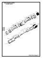
#158 PIGGYBACK GEARNG AND DRIVE SHAFTS

13
PART NO.
612795
615752
617189
617190
619156
619157
619293
619383
619403
PARTS LIST — #158 PIGGYBACK GEARING AND DRIVE SHAFTS
QTY.
1
1
1
1
1
1
1
2
1
QTY.
2
1
1
3
1
1
1
2
PART NO.
619427
619674
619742
619743
812232
844966
847095
865184
NAME OF PART
Drive Gear Key
S150 Drive Shaft
Gear Housing
Housing Adapter Screw
Retainer Ring
BaII Bearing
Idler Gear Ball Bearing
Housing Cover Screw
NAME OF PART
Gear Housing Cover
Heavy Duty Gear Cover
Drive Shaft Adapter
Gear Housing Adapter
Worm Pin
Worm Retainer Ring
S275 Drive Shaft
Housing Cover Needle Bearing
Gear Spacer
DISASSEMBLY INSTRUCTIONS
#158 PIGGYBACK GEAR HOUSING
Unscrew the two (2) housing cover screws and remove the
gear housing cover. Remove the idler gear, drive gear, gear
spacer and drive gear keys from the housing assembly. The
drive shaft assembly may now be pressed out the rear of
the gear housing. If the drive shaft and drive shaft adapter
need to be disassembled, install the drive gear keys and
gear spacer onto the drive shaft adapter and unscrew the
drive shaft.
REASSEMBLY INSTRUCTIONS
#158 PIGGYBACK GEAR HOUSING
Wash all parts in a solvent and inspect for damage
or wear. If the housing cover needle bearings are
replaced, they should be pressed in from the rear
of the cover. Before installing the gear housing
cover, all bearings and gears should receive a gen-
erous amount of "Lubriplate T-517" grease or equivalent.
#158

14
PART NO.
611157
613109
613110
613162
613225
613234
613236
613241
613242
613248
613253
613254
613271
613273
613275
613278
613279
613280
613281
613282
613283
613284
613285
613294
613688
613697
615391
615466
615467
617397
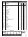
#158 PIGGYBACK POWER UNITS
PARTS LIST — #158 PIGGYBACK POWER UNITS
PART NO.
617398(V)
617608
617609
619421
619526
619527
619731 (V)
619732 (V)
619734 (V)
619735 (V)
619987
812165
812231
842515 (V)
843618
844111
844265
844303 (V)
844308
844312
845409 (V)
845744
847511
847548 (V)
863365
864471
882209
NAME OF PART
Handle (Incl. 613688, 842515
844265, 847548)
Rotor Shaft
Pinion Gear
Lock Nut
Swivel
Swivel Bushing
Governor Jet Cam
Knob
Cam Bushing
Governor Jet
Governor Jet
Throttle Valve Stop Pin
Throttle Valve Retainer Ring
Spring
Rotor Bearing Retainer Ring
Trigger Pin
Steel Ball (1/8")
(Variable speed requires 3)
"O"-Ring 3/16" x 5/16"
"O"-Ring 3/8" x 9/16"
"O"-Ring 5/8" x 13/16"
Knob Pin
Swivel Retainer Ring
Rear Rotor Bearing
Knob Stop Pin
Rotor Shaft Key
Planet Cage Bearing
Air Line Fitting
QTY.
1
1
1
1
1
1
4
1
1
1
1
1
6
1
1
1
3
3
1
1
1
1
1
1
1
1
1
1
1
1
QTY.
1
1
1
1
1
1
1
1
4
1
1
1
1
1
1
1
2
1
2
1
1
1
1
1
2
1
1
NOTE: (V) Variable speed units only.
NAME OF PART
Swivel Assembly (Incl. 619526)
619527-5. 844312-9. 845744)
Gasket
Screen
Cylinder Pin
Cylinder
Rotor
Rotor Blade
Rear Bearing Plate
Exhaust Sleeve
Front Rotor Bearing
Throttle Valve Washer
Throttle Valve (Incl. 812165)
Planet Gear Bearing
Front Bearing Plate
Motor Housing
Planet Cage Washer
Planet Gear Pin
Planet Gear
Planet Cage Bearing
Clamp Ring
Handle Nut
Planet Cage
Internal Gear
Rotor Bearing Retainer
Throttle Valve Bushing
Trigger
Exhaust Deflector
Muffler Screen
Muffler Screen
Handle (Incl. 613688, 619987)

15
#158 STRAIGHT MODEL
POWER UNITS
Parts list on page 17
95 thru 245 on page16

16
#158 STRAIGHT MODEL
POWER UNITS
Parts list on page 17

17
PART NO.
613102
613109
613110
613162
613225
613234
613236
613241
613242
613248
613253
613254
613271
613273
613274
613275
613278
613279
613280
613281
613282
613283
613285
613294
613688
613697
613828
615391
615466
615467
617113
617305
617367
617368
617369
617370
617397
617398(V)
617608
617609
617610
617644
617728
619731(V)
619732(V)
619734(V)
619735(V)
619987
812165
812231
834228
842515(V)
843618
844111
844265
844303(V)
844308
845409(V)
847511
847548(V)
863365
864471
PARTS LIST — #158 STRAIGHT POWER UNITSQUANITY
95
135
165
190
245
RPM
RANGES
175
215
265
380
445
350
420
525
700
850
750
900
1100
1500
1800
1450
1745
2175
2900
3600
1
1
1
1
1
1
4
1
1
1
1
1
12
1
1
1
2
6
6
2
1
1
1
1
1
1
1
1
1
1
1
-
-
-
1
-
1
1
1
-
-
1
1
1
1
1
1
1
1
1
2
-
1
1
2
1
2
1
1
-
2
2
1
DESCRIPTION
Inlet Bushing
Gasket
Air Screen
Cylinder Pin
Cylinder
Rotor
Rotor Blade
Rear Bearing Plate
Sleeve
Front Rotor Bearing
Throttle Valve Washer
Throttle Valve (incl. 812165)
Planet Wheel Bearing
Front Bearing Plate
Rotor Shaft
Motor Housing
Planet Cage Washer
Planet Wheel Pin
Planet Wheel
Planet Cage Bearing
Clamp Ring
Handle Nut
Internal Gear
Bearing Retainer Nut
Bushing
Trigger
Name Plate
Exhaust Deflector
Muffler Screen
Muffler Screen
Drill Head Adapter
Planet Wheel
Planet Cage
Planet Cage
Internal Gear and Housing
Planet Cage Washer
Handle (incl. 613688, 619987)
Handle (incl. 613688, 842515, 844265, 847548)
Rotor Shaft
Pinion Gear
Planet Cage
Planet Cage
Planet Cage
Governor Jet Cam
Knob
Cam Bushing
Governor Jet
Governor Jet
Pin
Retainer Ring
Driver Screw
Spring
Shaft Retainer Ring
Trigger Pin
Steel Ball (1/8") - Variable Speed Requires 3
"O"-Ring 3/16" x 5/16"
"O"-Ring 3/8" x 9/16"
Knob Pin
Rear Rotor Bearing
Pin
Rotor Key
Planet Cage Bearing
Air Fitting
1
1
1
1
1
1
4
1
1
1
1
1
12
1
1
1
1
6
3
2
1
1
1
1
1
1
1
1
1
1
1
3
1
1
1
1
1
1
-
-
-
-
-
1
1
1
1
1
1
1
2
1
1
1
2
1
2
1
1
1
2
2
1
1
1
1
1
1
1
4
1
1
1
1
1
12
1
-
1
-
6
-
2
1
1
1
1
1
1
1
1
1
1
1
6
-
1
1
2
1
1
1
1
1
-
-
1
1
1
1
1
1
1
2
1
-
1
2
1
2
1
1
1
2
2
1
1
1
1
1
1
1
4
1
1
1
1
1
6
1
1
1
1
3
3
1
1
1
1
1
1
1
1
1
1
1
1
-
-
-
-
-
1
1
-
-
-
-
1
1
1
1
1
1
1
1
2
1
1
1
2
1
2
1
1
1
2
1
1
1
1
1
1
1
1
4
1
1
1
1
1
6
1
-
1
-
3
-
1
1
1
1
1
1
1
1
1
1
1
1
3
-
1
-
1
1
1
1
1
-
-
-
-
1
1
1
1
1
1
2
1
-
1
2
1
2
1
1
1
2
1
1
NOTE: (V) — Variable Speed Units Only.
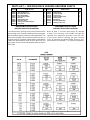
Governor
Power Unit
R.P.M.
Rotor Shaft
R.P.M.
611236
245
445
850
1,800
3,600
15,000
611237
190
380
700
1,500
2,900
12,000
611238
165
265
525
1,100
2,175
9,000
611239
135
215
420
900
1,745
7,200
611240
95
175
350
750
1,450
6,000
GOVERNOR CHART ALL VARIABLE
SPEED TOOL
REQUIRE THE
611240-3
GOVERNOR.

18
NOTES

19
NOTES

20
CooperTools
7007 Pinemont
Houston, Texas 77040
Phone: (713) 462-4521
Fax: (713) 460-7008
www.cooperindustries.com
-
 1
1
-
 2
2
-
 3
3
-
 4
4
-
 5
5
-
 6
6
-
 7
7
-
 8
8
-
 9
9
-
 10
10
-
 11
11
-
 12
12
-
 13
13
-
 14
14
-
 15
15
-
 16
16
-
 17
17
-
 18
18
-
 19
19
-
 20
20


Cooper Tools Quackenbush 158QGDA User manual
- Category
- Power drills
- Type
- User manual
Ask a question and I''ll find the answer in the document
Finding information in a document is now easier with AI
Related papers


Other documents
-
 Quackenbush 15QDB-S125 Operation & Service Manual
-
Airetool 1753-R-190 Owner's manual
-
Chevrolet 1967 Chevelle Overhaul Manual
-
Ingersoll-Rand 7LJ1B1 Maintenance Information
-
-
Ingersoll-Rand QS201B Operation and Maintenance Manual
-
-
-
-
