
1
0548EN August 2018
Metering systeMs
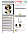
Heat Interface UnIt w/ Heat excHanger for HeatIng
ge556Y171 (ge556-1 serIes)
047U53338
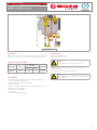
Technical data
• Max. working temperature: 90 °C
• Max. working pressure: 16 bar
Warning.
Maximum dierential pressure for the primary side = 4 bar
• Maximum working pressure of the heating secondary circuit: 3 bar
(safety valve setting)
• Nominal primary ow: 670 l/h @ 80 °C for 17,4 kW
Warning.
The HIU can be used in closed boiler rooms for operation with non-
aggressive uids (water, glycol-based water in compliance with VDI
2035/ÖNORM 5195).
Description
GE556Y171 is an Heat Interface Unit (HIU) for heating production; it is fed
by means of hot water from centralised boiler plant (e.g. district heating).
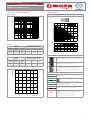
Versions and product codes
Product code Type
Heat exchanger nominal
power [kW]
Jig with valves
Heating SHW
GE556Y171 Heating 17,4 -
GE551Y081
GE551Y083
Main features
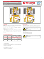
• Painted (RAL9010) steel cabinet, for external installation, with key lock.
• Heat exchanger for the heating function.
• Heating handling with controlled temperature.
• Spacer for the meter.
• Expansion vessel, safety valve and high eciency circulator (15/6), all comply
with ErP Directive (2009/125/CE).
• Motorised zone valve for heating.
• 3/4“ connections.
• Dynamic balancing valve, R206A series.
GE556Y171

2
0548EN August 2018
Metering systeMs
Heat Interface UnIt w/ Heat excHanger for HeatIng
ge556Y171 (ge556-1 serIes)
047U53338
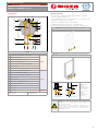
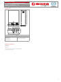
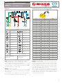
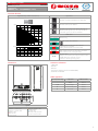
Components
24
18
8
15
20
16
23
21
22
2
19
4
6
1
17
3
5
C D
F
G
Legend
1 Automatic air vent with hygroscopic gasket
PRIMARY
2 Dynamic balancing valve
3 Motorised heating 2 way zone valve
4 Spacer pipe for energy meter
5 Temperature probe housing for energy meter
6 Primary by-pass
8 Thermostatic head R462L for temperature control of heating
15 Heat exchanger, sanitary hot water function
HEATING
16 Sensor of thermostatic head R462L
17 Automatic air vent with hygroscopic gasket
18 Pressure switch
19 Expansion vessel
20 Ball valve for circulator maintenance
21 High eciency circulator
22 Manometer
23 Safety valve
24 Electric box CONTROLS
C: Primary outlet
D: Primary inlet
F: Heating delivery
G: Heating return
Optional components
On each HIUs, it is possible to install the following optional components:
• Thermal energy meter: GE552 series
The ow temperature sensor of energy meter has to be installed into the
appropriate housing (Components - Ref. 5).
• Insulation in expanded PEx: product code GE551Y180
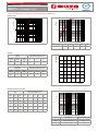
• Template with valves and 3/4” connections: code GE551Y081
• Template with valves, lters and Ø 22 mm connections: codeGE551Y083
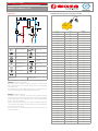
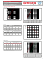
GE551Y081 - Template with 4 valves (connections from below)
GE551Y083 - Template with 4 valves (possibility of connections from above)
3
2
3
2
1
4
4
5
6
1
6
5
FLUID FROM ABOVE
3
2
3
2
1
4
4
5
6
1
6
5
FLUID FROM BELOW
1) Metallic frame
2) Filter
3) Dirt-separator
4) Joint that allows
the connection
from above or from
below
6) Ball valve
7) System pipes,
Ø 22 mm
Warning.
The installation should be undertaken by suitably qualied and
authorised personnel only.
Observe the EU norms and regulations concerning the use
(installation, xing, etc.), the operation, the recalibration and the
replacement the meters. Please refer to the assembly instructions
supplied with any meter.

3
0548EN August 2018
Metering systeMs
Heat Interface UnIt w/ Heat excHanger for HeatIng
ge556Y171 (ge556-1 serIes)
047U53338
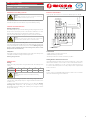
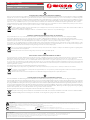
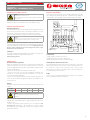
Operation
C
D
F
G
E
P
A
Legend
Automatic air vent with
hygroscopic gasket
Heat exchanger
Dynamic balancing valve Thermostatic head R462L
Motorised 2 way zone
valve
Manometer
E
Spacer for energy meter
Sensor of thermostatic
head R462L
Temperature probe
housing for energy meter
Expansion vessel
Primary by-pass High eciency circulator
P
Pressure switch Safety valve
Ball valve for circulator maintenance
C: Primary outlet
D: Primary inlet
F: Heating delivery
G: Heating return
HEATING: delivery (F) and return (G).
The heating circuit is composed of the heat exchanger, a circulator, a ball
valve, a pressure switch, an air vent valve, an expansion vessel, a safety valve
and a manometer.
For the heating provide for a ling system, that is a connection from the
sanitary to the heating, with an appropriate backow preventer.
PRIMARY: inlet (D) and outlet (C).
The primary circuit is composed of an air vent valve, a dynamic balancing
valve, a 2-way zone valve motorised, a brass spacer, an housing for installing
the temperature probe of the energy meter, a by-pass valve and a thermostatic
head to control the temperature.
In place of the brass spacer (Components - Ref. 4) a thermal energy meter
can be mounted, by installing the temperature probe in the appropriate
housing (Components - Ref. 5).
The zone valve can control the heating by means of a thermostat (to be
ordered separately).
R206A dynamic balancing valve setting (∆p: 30-400 kPa)
8 mm
l / sec l / h Setting
0.113 406 1.0
0.119 427 1.1
0.125 449 1.2
0.131 470 1.3
0.137 492 1.4
0.143 513 1.5
0.149 535 1.6
0.155 556 1.7
0.161 578 1.8
0.167 599 1.9
0.172 621 2.0
0.178 642 2.1
0.184 664 2.2
0.190 685 2.3
0.196 707 2.4
0.202 728 2.5
0.208 750 2.6
0.214 771 2.7
0.220 793 2.8
0.226 814 2.9
0.232 836 3.0
0.238 857 3.1
0.244 879 3.2
0.250 900 3.3
0.256 922 3.4
0.262 943 3.5
0.268 965 3.6
0.274 987 3.7
0.280 1010 3.8
0.286 1030 3.9
0.292 1050 4.0
0.298 1070 4.1
0.304 1090 4.2
0.310 1120 4.3
0.316 1140 4.4
0.322 1160 4.5
0.328 1180 4.6
0.334 1200 4.7
0.340 1220 4.8
0.346 1240 4.9
0.352 1270 5.0

4
0548EN August 2018
Metering systeMs
Heat Interface UnIt w/ Heat excHanger for HeatIng
ge556Y171 (ge556-1 serIes)
047U53338
Protection and safety systems
Warning.
Danger of burns and electric shocks. Access to the HIU should be by
suitably qualied and authorised personnel only.
It is important that the access to the HIU is made only by suitably qualied
and authorised personnel: the cabinets are provided with key locking.
Controls and maintenance
Heating circuit pressure
Periodically inspect the pressure of the heating circuit by using the manometer
(Components - Ref. 22): the pressure value must be maintained over 1 bar
(pressure values under 1 bar can damage the circulator by cavitation).
A pressure switch with 0,8 bar settings is provide to protect the circulator.
Warning.
Circulator stops if the pressure is below 0,8 bar due to the pressure
switch device. Please, rell the system to restart the circulator.
Provide a lling system for the heating, that is a connection from the sanitary
side to the heating with a backow preventer. during lling be aware that the
safety valve will activate at 3 bar (Components - Ref. 23). Warning: danger of
burns. In order to eliminate the air in the heating circuit, use the air vent
(Components - Ref. 1 and Ref. 17).
Safety valve
Periodically operate the manual handwheel of the safety valve (Components
- Ref. 23). Be careful the discharge of water may be hot.
Warning: danger of burns.
Adjustments
Heating
Adjust the heating temperature using the thermostatic head (Components
- Ref. 8):
Position 1 2 3 4 5
Temperature [°C] 23 34 45 56 67
Warning.
Provide a safety thermostat for the low temperature heating
applications.
If you notice that the rating temperature of the heating is higher than the set
value, the ow of the primary may be too high and the thermostatic head is
not able to close.
To balance the heating production functions, you can adjust the dynamic
balancing valve (Components - Ref. 2). Finally, it is possible to change
the heating power by modifying the circulator speed using the red knob
(Components - Ref. 21).
Electrical connections
On the top left of the HIU there is an electrical box IP55 (Componenti - Ref. 24).
Bianco - White
Rosso - Red
5
6
7
1817 19 20
8
9
10
21 22 23
11
12
24
Marrone - BrownMarrone - Brown
PRESSOSTATO
PRESSURE SWITCH
NO
C
NC
CRONOTERMOSTATO
CHRONOTHERMOSTAT
TERRA - GROUND
230 V
NEUTRO - NEUTRAL
Verde/Giallo - Green/Yellow
TERRA AL SATELLITE
GROUND TO THE SATELLITE
Verde/Giallo - Green/Yellow
Verde/Giallo
Green/Yellow
CIRCOLATORE
CIRCULATOR
ATTUATORE
VALVOLA DI ZONA A 2 VIE
ACTUATOR
2-WAY ZONE VALVE
Blu - Blue
Technical data
• Supply voltage for circulator: 230 V / 50 Hz
• Maximum electrical power: 43 W
• Electrical power for the circulator: 3÷45 W / 0,03÷0,44 A
Heating demand - thermostat connection
The heating demand should be given via the normally open contact of the
thermostat to terminal n° 8. The common contact of the thermostat has to
be connected to terminal n° 9. For the connection of the thermostat use a
2-conductor cable with 0,5 mm
2
section. No polarity need be complied with
for the connections.
M-Bus
For the connection of the M-Bus data transmission cable to the concentrator
refer to the thermal energy meters datasheet.

5
0548EN August 2018
Metering systeMs
Heat Interface UnIt w/ Heat excHanger for HeatIng
ge556Y171 (ge556-1 serIes)
047U53338
Small heat exchanger (GE556Y171)
Primary circuit
Primary circuit for heating production, dynamic balancing valve fully open
1,00
0,10
0,01
0,1 1,0 10,0
Q [m
3
/h]
Δp [bar]
Kv = 1,55
Heating
Heating
Radiators
Flowrate [l/h] and primary outlet
temperature (radiators 65-53 °C)
Circulator
speed
Flowrate
[m
3
/h]
Power
[kW]
80 °C 75 °C 72 °C
Max 1,2 17,4
670
(57 °C)
950
(59 °C)
1350
(61 °C)
Dati del circuito primario per riscaldamento con radiatori
Heating
Radiant oor
Flowrate [l/h] and primary outlet
temperature (radiators 45-38 °C)
Circulator
speed
Flowrate
[m
3
/h]
Power
[kW]
70 °C 65 °C 60 °C
Max 1,2 10,0
280
(39 °C)
340
(39 °C)
430
(40 °C)
Primary circuit data for oor radiant heating.
Circulator for heating
0
0 200 400 600 800 1000 1200
1
2
3
4
5
6
7
∆p [m H
2
O]
Q [l/h]
Circulator features
Operations
Automatic constant pressure dierence (recommended).
Automatic variable pressure dierence.
Automatic air vent routine (10 min duration): the pump
runs alternatively with high and low speeds to help
air bubbles to collect and to go to the air vent in the
installation.
LED - errors
green continuous
Normal running.
green ashing
Automatic operation for air elimination.
green/red ashing
Abnormal situation (pump functional but stopped):
1) Undervoltage or overvoltage
2) Wrong temperature (uid or room temperature)
red ashing
Pump stopped (permanent error: the pump need a manual
reset). It can be necessary to change the pump.
NO LED
No power supply:
1) Pump is not connected to power supply: check cable
connection.
2) LED is damaged: check if pump is running.
3) Electronics are damaged: change pump.
High-eciency circulator 15/6 (230 V)
p-costante
6
5
4
3
2
1
0
0 0,5 1 1,5 2 2,5 3
Q [m
3
/h]
Q [m
3
/h]
H [m]
0
0 0,5
1
1,5 2 2,5 3
10
20
30
40
P1 [w]
1 m
0,5 m
2 m
4 m
3 m
5 m
max

6
0548EN August 2018
Metering systeMs
Heat Interface UnIt w/ Heat excHanger for HeatIng
ge556Y171 (ge556-1 serIes)
047U53338
Dimensions
450
450
65
92 55 57 49
157
180
630
180
C
D
F
GX
Y
Legend
C: Primary outlet
D: Primary inlet
F: Heating delivery
G: Heating return
X: Hole for safety valve drain
Y: Hole for electrical cables
Dimensions in mm
Normative references
• UNI EN 1434
• EN 60751
• EN 61107
• Measuring Instruments Directive 2004/22/CE (MID)
• ErP Directive 2004/22/CE

7
0548EN August 2018
Metering systeMs
Heat Interface UnIt w/ Heat excHanger for HeatIng
ge556Y171 (ge556-1 serIes)
047U53338

8
0548EN August 2018
Metering systeMs
Heat Interface UnIt w/ Heat excHanger for HeatIng
ge556Y171 (ge556-1 serIes)
047U53338
Safety Warning
Installation, commissioning and periodical maintenance of the product must be carried out by qualied operators in compliance with national regulations and/or local standards. A qualied installer must take
all required measures, including use of Individual Protection Devices, for his and others’ safety.
An improper installation may damage people, animals or objects towards which Giacomini S.p.A. may not be held liable.
Product Disposal
Do not dispose of product as municipal waste at the end of its life cycle.
Dispose of product at a special recycling platform managed by local authorities or at retailers providing this type of service.
Package Disposal
Carton boxes: paper recycling.
Plastic bags and bubble wrap: plastic recycling.
Additional information
For more information, go to www.giacomini.com or contact our technical assistance service: ' +39 0322 923372 6 +39 0322 923255 * [email protected]
This document provides only general indications. Giacomini S.p.A. may change at any time, without notice and for technical or commercial reasons, the items included herewith.
The information included in this technical sheet do not exempt the user from strictly complying with the rules and good practice standards in force.
Giacomini S.p.A. Via per Alzo, 39 - 28017 San Maurizio d’Opaglio (NO) Italy
IT
AVVERTENZE PER IL CORRETTO SMALTIMENTO DEL PRODOTTO
Questo prodotto rientra nel campo di applicazione della Direttiva 2012/19/UE riguardante la gestione dei riuti di apparecchiature elettriche ed elettroniche (RAEE).
L’apparecchio non deve essere eliminato con gli scarti domestici in quanto composto da diversi materiali che possono essere riciclati presso le strutture adeguate.
Informarsi attraverso l’autorità comunale per quanto riguarda l’ubicazione delle piattaforme ecologiche atte a ricevere il prodotto per lo smaltimento ed il suo
successivo corretto riciclaggio. Si ricorda, inoltre, che a fronte di acquisto di apparecchio equivalente, il distributore è tenuto al ritiro gratuito del prodotto da smaltire.
Il prodotto non è potenzialmente pericoloso per la salute umana e l’ambiente, ma se abbandonato nell’ambiente impatta negativamente sull’ecosistema.
Leggere attentamente le istruzioni prima di utilizzare l’apparecchio per la prima volta. Si raccomanda di non usare assolutamente il prodotto per un uso diverso
da quello a cui è stato destinato, essendoci pericolo di shock elettrico se usato impropriamente.
Il simbolo del bidone barrato, presente sull’etichetta posta sull’apparecchio, indica la rispondenza di tale prodotto alla normativa relativa ai riuti di
apparecchiature elettriche ed elettroniche.
L’abbandono nell’ambiente dell’apparecchiatura o lo smaltimento abusivo della stessa sono puniti dalla legge.
EN
IMPORTANT INFORMATION FOR CORRECT DISPOSAL OF THE PRODUCT
This product falls into the scope of the Directive 2012/19/EU concerning the management of Waste Electrical and Electronic Equipment (WEEE).
This product shall not be dispose in to the domestic waste as it is made of dierent materials that have to be recycled at the appropriate facilities.
Inquire through the municipal authority regarding the location of the ecological platforms to receive the product for disposal and its subsequent correct recycling.
Furthermore, upon purchase of an equivalent appliance, the distributor is obliged to collect the product for disposal free of charge.
The product is not potentially dangerous for human health and the environment, but if abandoned in the environment can have negative impact on the
environment. Read carefully the instructions before using the product for the rst time. It is recommended that you do not use the product for any purpose
rather than those for which it was intended, there being a danger of electric shock if used improperly.
The crossed-out wheeled dustbin symbol, on the label on the product, indicates the compliance of this product with the regulations regarding Waste
Electrical and Electronic Equipment.
Abandonment in the environment or illegal disposal of the product is punishable by law.
FR
AVERTISSEMENTS POUR L’ÉLIMINATION CORRECTE DU PRODUIT
Ce produit entre dans le champ d’application de la directive 2012/19 / UE relative à la gestion des déchets équipements électriques et électroniques (DEEE).
L’appareil ne doit pas être jeté avec les ordures ménagères car il est fait de diérents matériaux pouvant être recyclés dans des centres appropriés.
Renseignez-vous auprès de l’autorité locale concernant l’emplacement des plates-formes écologiques appropriées pour recevoir le produit pour sa destruction
et son recyclage correct ultérieur. Il convient également de rappeler que, en cas d’achat d’un appareil équivalent, le distributeur est tenu de collecter le produit
à détruire. Le produit n’est potentiellement pas dangereux pour la santé humaine et l’environnement, mais s’il est abandonné dans l’environnement, il a un
impact négatif sur l’écosystème.
Lisez attentivement les instructions avant d’utiliser l’appareil pour la première fois.
Il est interdit d’utiliser le produit pour un usage diérent de celui auquel il était destiné, il y a risque de choc électrique si utilisé incorrectement.
Le symbole de la poubelle barrée sur l’étiquette de l’appareil indique sa correspondance produit à la législation relative aux déchets d’équipements
électriques et électroniques.
L’abandon dans l’environnement de l’équipement ou l’élimination illégale de l’équipement est punissable par la loi.
DE
WICHTIGE HINWEISE ZUR KORREKTEN ENTSORGUNG DES PRODUKTS
Dieses Produkt fällt in den Anwendungsbereich der Richtlinie 2012/19/EU über die Entsorgung von Elektro- und Elektronik - Altgeräten (WEEE).
Dieses Produkt darf nicht in den Hausmüll entsorgt werden, da es aus verschiedenen Materialien besteht, die in entsprechenden Einrichtungen recycelt werden
müssen. Erkundigen sie sich bei ihrer Gemeinde nach dem Standort des nächsten Recyclinghofs bzw. der nächsten Annahmestelle, um das Produkt dem
Recycling zuzuführen bzw. fachgerecht zu entsorgen. Darüber hinaus ist der Händler verpichtet, das Produkt beim Kauf eines gleichwertigen Geräts kostenlos zu
entsorgen. Das Produkt ist für die menschliche Gesundheit und die Umwelt potenziell nicht gefährlich. Diese können sich aber, falls sie in der Umwelt gelangen,
negativ auf diese auswirken. Lesen Sie daher vor dem ersten Gebrauch des Produkts die Inbetriebnahme-, Bedienungs- und Entsorgungsanweisungen sorgfältig
durch. Es wird empfohlen, dass Sie das Produkt nur für den vorgesehenen Zweck verwenden.
Bei unsachgemäßer Verwendung bzw. Fehlgebrauch besteht die Gefahr eines elektrischen Schlags.
Das Symbol der durchgestrichenen Mülltonne auf dem Etikett des Produkts weist auf die Konformität dieses Produkts zu den Vorschriften für Elektro-
und Elektronik-Altgeräte hin. Das Ablagern in der Umwelt oder die illegale Entsorgung des Produkts ist strafbar.

1
0865EN August 2018
Metering systeMs
Heat Interface UnIt w/ doUble Heat excHanger In parallel
confIgUratIon
ge556Y176 - 177 (ge556-1 serIes)
047U57408
Technical data
• Max. working temperature of the primary circuit and secondary circuits
(heating and DHW): 90 °C
• Max. working pressure of the primary circuit and secondary DHW: 16 bar
Warning.
Maximum dierential pressure for the primary side = 4 bar
(due to the priority valve)
• Maximum working pressure of the heating secondary circuit: 3 bar (safety
valve setting)
• Nominal primary ow:
975 l/h @ 80 °C for 56 kW (GE556Y176)
970 l/h @ 80 °C for 67 kW (GE556Y177)
Warning.
The satellite can be used in closed boiler rooms for operation with
non-aggressive uids (water, glycol-based water in compliance with
VDI 2035/ÖNORM 5195).
Description
GE556-1 series is composed of Heat Interface Units (HIU) for heating and
DHW (Domestic Hot Water) production; they are fed by means of hot water
from centralised boiler plant (e.g. district heating).
The present version uses a conguration of two heat exchangers in
parallel, this has two principal advantages:
• Parallel and non-intermittent handling of the domestic hot water and
heating functions.
• Higher safety, the heating circuit is a sealed pressurised system should
there be any leaks within property only a small amount of water will be
discharged.
Versions and product codes
Product code Type
Heat exchanger
nominal power [kW]
Template
with valves
Heating DHW
GE556Y176
Heating and
DHW production
17,4 56
GE551Y082
GE551Y084
GE556Y177
Heating and
DHW production
17,4 67
GE551Y082
GE551Y084
Main features
• Heating handling with controlled temperature.
• Spacers for the meters.
• Expansion vessel, safety valve and high eciency circulator (15/6), all comply
with ErP Directive (2009/125/CE).
• Motorised zone valve for heating.
• 3/4“ connections.
• Dynamic balancing valve, R206A series
• Static balancing valve, R206B-1 series
• WRAS certied components for the domestic hot water circuit.
GE556Y176 GE556Y177

2
0865EN August 2018
Metering systeMs
Heat Interface UnIt w/ doUble Heat excHanger In parallel
confIgUratIon
ge556Y176 - 177 (ge556-1 serIes)
047U57408
Components
C D
A
B E
25
8
19
16
13
17
7
21
22
24
23
11
12
10
20
9
14
15
6
4
2
5
1
18
3
F
G
Legend
1 Automatic air vent with hygroscopic gasket
PRIMARY
2 Dynamic balancing valve
3 Motorised 2 way zone valve, for heating
4 Spacer pipe for energy meter
5 Temperature probe housing for energy meter
6 Primary by-pass
7 Static balancing valve
8 Thermostatic head R462L for temperature control of heating
9
Priority valve for domestic hot water function
10 Check valve, primary circuit
11
Heat exchanger, domestic hot water function
DHW
PRODUCTION
12 Flow switch
13 TMV2 & TMV3 thermostatic mixing valve
14 Spacer pipe for domestic hot water meter
15
Check valve
16
Heat exchanger, heating function
HEATING
17 Sensor of thermostatic head R462L
18 Automatic air vent with hygroscopic gasket
19 Pressure switch
20 Expansion vessel
21 Ball valve for circulator maintenance
22
Circulator
23 Manometer
24
Safety valve
25 Electric box CONTROLS
A: Domestic cold water inlet
B: Domestic cold water outlet
C: Primary outlet
D: Primary intlet
E: Domestic hot water outlet
F: Heating delivery
G: Heating return
Optional components
On each satellites, it is possible to install the following optional components:
• Thermal energy meter: GE552 series
The ow temperature sensor of energy meter has to be installed into the
appropriate housing (Components - Ref. 5).
• Domestic cold water meter: GE552-2 series
• Insulation in expanded PEx: code GE551Y180
• Template with valves and 3/4” connections: code GE551Y082
• Template with valves, lters and Ø 22 mm connections: code GE551Y084
GE551Y082 - Template with 7 valves (connections from below)
GE551Y084 - Template with 7 valves (possibility of connections from above)
3
2
3
2
1
4
4
5
6
1
6
5
FLUID FROM ABOVE
3
2
3
2
1
4
4
5
6
1
6
5
FLUID FROM BELOW
1) Metallic frame
2) Filter
3) Dirt-separator
4) Joint that allows
the connection
from above or from
below
6) Ball valve
7) System pipes,
Ø 22 mm
Warning.
The installation should be undertaken by suitably qualied and
authorised personnel only.
Observe the EU norms and regulations concerning the use
(installation, xing, etc.), the operation, the recalibration and the
replacement the meters. Please refer to the assembly instructions
supplied with any meter.

3
0865EN August 2018
Metering systeMs
Heat Interface UnIt w/ doUble Heat excHanger In parallel
confIgUratIon
ge556Y176 - 177 (ge556-1 serIes)
047U57408
Operation
C
D
F
G
B E
A
W
F
E
P
A
B
Legend
Automatic air vent with
hygroscopic gasket
Heat exchanger
Dynamic balancing valve
F
Flow switch
Motorised 2 way zone
valve
Manometer
E
Spacer for energy meter
TMV2 & TMV3
thermostatic mixing valve
Temperature probe
housing for energy meter
B
Static balancing valve
Primary by-pass
W
Spacer for domestic cold
water meter
Priority valve
Sensor of thermostatic
head R462L
P
Pressure switch Expansion vessel
Ball valve for circulator
maintenance
High eciency circulator
Thermostatic head
R462L
Safety valve
Check valve
A: Domestic cold water inlet
B: Domestic cold water outlet
C: Primary outlet
D: Primary intlet
E: Domestic hot water outlet
F: Heating delivery
G: Heating return
R206A dynamic balancing valve setting (∆p: 30-400 kPa)
8 mm
l / sec l / h Setting
0.113 406 1.0
0.119 427 1.1
0.125 449 1.2
0.131 470 1.3
0.137 492 1.4
0.143 513 1.5
0.149 535 1.6
0.155 556 1.7
0.161 578 1.8
0.167 599 1.9
0.172 621 2.0
0.178 642 2.1
0.184 664 2.2
0.190 685 2.3
0.196 707 2.4
0.202 728 2.5
0.208 750 2.6
0.214 771 2.7
0.220 793 2.8
0.226 814 2.9
0.232 836 3.0
0.238 857 3.1
0.244 879 3.2
0.250 900 3.3
0.256 922 3.4
0.262 943 3.5
0.268 965 3.6
0.274 987 3.7
0.280 1010 3.8
0.286 1030 3.9
0.292 1050 4.0
0.298 1070 4.1
0.304 1090 4.2
0.310 1120 4.3
0.316 1140 4.4
0.322 1160 4.5
0.328 1180 4.6
0.334 1200 4.7
0.340 1220 4.8
0.346 1240 4.9
0.352 1270 5.0
DHW: cold water inlet (A), cold water outlet (B), hot water outlet (E).
The domestic water circuit is composed of a heat exchanger, a brass spacer, a
ow switch, a thermostatic mixing valve and a check valve.
In place of the brass spacer (Components - Ref. 14) a domestic cold water
meter can be installed. A TMV2+TMV3 thermostatic mixing valve regulates
the temperature of domestic hot water (DHW).
HEATING: delivery (F) and return (G).
The heating circuit is composed of the heat exchanger, a circulator, a ball
valve, a pressure switch, an air vent valve, an expansion vessel, a safety valve
and a manometer.
For the heating provide for a ling system, that is a connection from the
domestic to the heating, with an appropriate backow preventer.
PRIMARY: inlet (D) and outlet (C).
The primary circuit is divided into two sides: one is for the heating handling,
the other is for the production of DHW. It is composed of an air vent valve,
a dynamic balancing valve, a 2-way zone valve motorised, a brass spacer, an
housing for installing the temperature probe of the energy meter, a by-pass
valve, a static balancing valve, a thermostatic head to control the temperature,
a priority valve for DHW function and a check valve.
In place of the brass spacer (Components - Ref. 4) a thermal energy meter
can be mounted, by installing the temperature probe in the appropriate
housing (Components - Ref. 5). If the ow switch is activated (by a domestic
hot water request), the priority valve closes the heating side and gives
power to the DHW production side.

4
0865EN August 2018
Metering systeMs
Heat Interface UnIt w/ doUble Heat excHanger In parallel
confIgUratIon
ge556Y176 - 177 (ge556-1 serIes)
047U57408
Protection and safety systems
Warning.
Danger of burns and electric shocks.
Access to the satellite should be by suitably qualied and authorised
personnel only.
It is important that the access to the satellite is made only by suitably qualied
and authorised personnel: the cabinets are provided with key locking.
Controls and maintenance
Heating circuit pressure
Periodically inspect the pressure of the heating circuit by using the manometer
(Components - Ref. 23): the pressure value must be maintained over 1 bar
(pressure values under 1 bar can damage the circulator by cavitation).
A pressure switch with 0,8 bar settings is provide to protect the circulator.
Warning.
Circulator stops if the pressure is below 0,8 bar due to the pressure
switch device. Please, rell the system to restart the circulator.
Provide a lling system for the heating, that is a connection from the domestic
side to the heating with a backow preventer. during lling be aware that the
safety valve will activate at 3 bar (Components - Ref. 24). Warning: danger of
burns. In order to eliminate the air in the heating circuit, use the air vent
(Components - Ref. 1 and Ref. 18).
Safety valve
Periodically operate the manual handwheel of the safety valve (Components
- Ref. 24). Be careful the discharge of water may be hot.
Warning: danger of burns.
Adjustments
Domestic hot water temperature
Adjust the temperature of the domestic hot water using the thermostatic
mixing valve (Components - Ref. 13). The adjustment has to be made by
means of a digital thermometer to put in contact with the outlet water, in this
way (factory default 40 °C):
• Remove the cap and release the locking nut form the stem.
• Using an 8 mm allen key rotate the temperature adjustment stem
anticlockwise to increase the mixed water temperature or clockwise to
reduce the mixed water temperature.
• Once the desired outlet temperature is reached, re-t the locking nut to the
stem to prevent unauthorised adjustment of the valve and replace the cap
on the valve body.
Heating
Adjust the heating temperature using the thermostatic head (Components
- Ref. 8):
Position 1 2 3 4 5
Temperature [°C] 23 34 45 56 67
Warning.
Provide a safety thermostat for the low temperature heating
applications.
If you notice that the rating temperature of the heating is higher than the set
value, the ow of the primary may be too high and the thermostatic head is
not able to close.
To balance the heating production functions, you can adjust the static
balancing valve (Components - Ref. 7). Finally, it is possible to change
the heating power by modifying the circulator speed using the red knob
(Components - Ref. 22).
Electrical connections
On the top left of the satellite there is an electrical box IP55 (Componenti - Ref.
25) containing a relay for the priority valve controlled by means of the ow
switch and the control and supply of the circulator (Components - Ref. 22).
Marrone - Brown
Marrone - Brown
Bianco - White
Rosso - Red
5
6
7
1817 19 20
8
9
10
21 22 23
11
12
24
Marrone - BrownMarrone - Brown
PRESSOSTATO
PRESSURE SWITCH
NO
C
NC
CRONOTERMOSTATO
CHRONOTHERMOSTAT
TERRA - GROUND
230 V
NEUTRO - NEUTRAL
Verde/Giallo - Green/Yellow
TERRA AL SATELLITE
GROUND TO THE SATELLITE
Verde/Giallo - Green/Yellow
Verde/Giallo
Green/Yellow
CIRCOLATORE
CIRCULATOR
FLUSSOSTATO ACS
SHW FLOW SWITCH
VALVOLA DI
PRIORITA’ ACS
SHW PRIORITY
VALVE
ATTUATORE
VALVOLA DI ZONA A 2 VIE
ACTUATOR
2-WAY ZONE VALVE
RELE’ - RELAIS
21
14
12
A2 A1
Nero - Black
Blu - Blue
Blu - Blue
Technical data
• Supply voltage for circulator: 230 V / 50 Hz.
• Maximum electrical power for the satellite: 49 W
• Electrical power for the circulator: 3÷45 W / 0,03÷0,44 A
Heating demand - thermostat connection
The heating demand should be given via the normally open contact of the
thermostat to terminal n°8. The common contact of the thermostat has to
be connected to connection n°12 on the relay. For the connection of the
thermostat use a 2-conductor cable with 0,5 mm
2
section. No polarity need
be complied with for the connections.
M-Bus
For the connection of the M-Bus data transmission cable to the concentrator
refer to the thermal energy meters datasheet.

5
0865EN August 2018
Metering systeMs
Heat Interface UnIt w/ doUble Heat excHanger In parallel
confIgUratIon
ge556Y176 - 177 (ge556-1 serIes)
047U57408
Small heat exchanger (GE556Y176)
Primary circuit
1,00
0,10
0,01
0,1 1,0 10,0
Q [m
3
/h]
Δp [bar]
0,66Kv =
0,74 0,84
0,87
0,86
R206B-1 opening % 20% 40% 60% 80% 100%
Kv 0,66 0,76 0,84 0,86 0,87
Primary circuit for heating, dynamic balancing valve fully open and regulation on
static balancing valve R206B-1
Primary circuit for domestic hot water production, dynamic balancing valve fully open
1,00
0,10
0,01
0,1 1,0 10,0
Q [m
3
/h]
Δp [bar]
Kv = 1,32
Heating
Heating
Radiators
Flowrate [l/h] and primary outlet
temperature (radiators 65-53 °C)
Circulator
speed
Flowrate
[m
3
/h]
Power
[kW]
80 °C 75 °C 72 °C
Max 1,2 17,4
670
(57 °C)
950
(59 °C)
1350
(61 °C)
Primary circuit data for radiator heating.
Heating
Radiant oor
Flowrate [l/h] and primary outlet
temperature (radiators 45-38 °C)
Circulator
speed
Flowrate
[m
3
/h]
Power
[kW]
70 °C 65 °C 60 °C
Max 1,2 10,0
280
(39 °C)
340
(39 °C)
430
(40 °C)
Primary circuit data for oor radiant heating.
Circulator for heating
0
0 200 400 600 800 1000 1200
1
2
3
4
5
6
7
∆p [m H
2
O]
Q [l/h]
DHW production
DHW
Flowrate [l/h] and primary outlet
temperature (DHW 10-50 °C)
l/min l/h kW 80 °C 75 °C 70 °C 65 °C 60 °C
12 720 33
510
(22,9 °C)
580
(25 °C)
690
(27,9 °C)
865
(31,4 °C)
1210
(36 °C)
15 900 42
670
(25,7 °C)
775
(28,1 °C)
935
(31,1 °C)
1200
(34,8 °C)
17 1020 47
785
(27,5 °C)
920
(30,2 °C)
1120
(33,2 °C)
1480
(37,1 °C)
20 1200 56
975
(30,2 °C)
1150
(32,9 °C)
1430
(36,1 °C)
Primary circuit data for domestic hot water production.
0,01
0,1 1,0 10,0
0,10
1,00
Δp [bar]
Q [m
3
/h]
1,05 4,4
Kv Description Ref. “Components” image
1,05 Domestic hot water A-E
4,40 Domestic cold water A-B
Hydraulic data for hot and cold domestic water circuits.

6
0865EN August 2018
Metering systeMs
Heat Interface UnIt w/ doUble Heat excHanger In parallel
confIgUratIon
ge556Y176 - 177 (ge556-1 serIes)
047U57408
Large heat exchanger for domestic water production (GE556Y177)
Primary circuit
1,00
0,10
0,01
0,1 1,0 10,0
Q [m
3
/h]
Δp [bar]
0,66Kv =
0,74 0,84
0,87
0,86
R206B-1 opening % 20% 40% 60% 80% 100%
Kv 0,66 0,76 0,84 0,86 0,87
Primary circuit for heating, dynamic balancing valve fully open and regulation on
static balancing valve R206B-1
Primary circuit for domestic hot water production, dynamic balancing valve fully open
1,00
0,10
0,01
0,1 1,0 10,0
Q [m
3
/h]
Δp [bar]
Kv = 1,5
Heating
Heating
Radiators
Flowrate [l/h] and primary outlet
temperature (radiators 65-53 °C)
Circulator
speed
Flowrate
[m
3
/h]
Power
[kW]
80 °C 75 °C 72 °C
Max 1,2 17,4
670
(57 °C)
950
(59 °C)
1350
(61 °C)
Primary circuit data for radiator heating.
Heating
Radiant oor
Flowrate [l/h] and primary outlet
temperature (radiators 45-38 °C)
Circulator
speed
Flowrate
[m
3
/h]
Power
[kW]
70 °C 65 °C 60 °C
Max 1,2 10,0
280
(39 °C)
340
(39 °C)
430
(40 °C)
Primary circuit data for oor radiant heating.
Circulator for heating
0
0 200 400 600 800 1000 1200
1
2
3
4
5
6
7
∆p [m H
2
O]
Q [l/h]
Domestic hot water production
Table 10 – Primary circuit data for domestic hot water production.
DHW
Flowrate [l/h] and primary outlet
temperature (DHW 10-50 °C)
l/min l/h kW 80 °C 75 °C 70 °C 65 °C 60 °C
12 720 33
450
(15,4 °C)
495
(16,9 °C)
565
(18,7 °C)
660
(21,3 °C)
825
(24,9 °C)
15 900 42
575
(16,8 °C)
640
(18,3 °C)
730
(20,4 °C)
870
(23,3 °C)
1105
(27,2 °C)
17 1020 47
660
(17,7 °C)
740
(19,4 °C)
850
(21,6 °C)
1010
(24,4°C)
1300
(28,5 °C)
20 1200 56
790
(18,9 °C)
890
(20,7 °C)
1030
(23,1 °C)
1260
(26,3 °C)
24 1430 67
970
(20,6 °C)
1100
(22,6 °C)
1280
(25,1 °C)
0,1
0,01
0,10
1,00
1,15 4,5
1,0 10,0
Q [m
3
/h]
Δp [bar]
Kv Description Ref. “Components” image
1,15 Domestic hot water A-E
4,5 Domestic cold water A-B
Hydraulic data for hot and cold domestic water circuits.

7
0865EN August 2018
Metering systeMs
Heat Interface UnIt w/ doUble Heat excHanger In parallel
confIgUratIon
ge556Y176 - 177 (ge556-1 serIes)
047U57408
Normative references
• UNI EN 1434
• EN 60751
• EN 61107
• Measuring Instruments Directive 2004/22/CE (MID)
• ErP Directive 2004/22/CE
WRAS approvals
Ref. “Components” image Components Certicate number
- Gaskets 1509514
11, 16 Heat exchanger 1403059
13 Thermostatic mixing valve 1405089
15 Check valve 1408704
Dimensions
450
450
65
30 37 55 57 49
50 45 62
180
630
180
A B
C
D
E
F
G
X
Y
Legend
A: Domestic cold water inlet
B: Domestic cold water outlet
C: Primary outlet
D: Primary intlet
E: Domestic hot water outlet
F: Heating delivery
G: Heating return
X: Hole for safety valve drain
Y: Hole for electrical cables
Dimensions in mm
Operations
Automatic constant pressure dierence (recommended).
Automatic variable pressure dierence.
Automatic air vent routine (10 min duration): the pump runs
alternatively with high and low speeds to help air bubbles to
collect and to go to the air vent in the installation.
LED - errors
green continuous
Normal running.
green ashing
Automatic operation for air elimination.
green/red ashing
Abnormal situation (pump functional but stopped):
1) Undervoltage or overvoltage
2) Wrong temperature (uid or room temperature)
red ashing
Pump stopped (permanent error: the pump need a manual
reset). It can be necessary to change the pump.
NO LED
No power supply:
1) Pump is not connected to power supply: check cable connection.
2) LED is damaged: check if pump is running.
3) Electronics are damaged: change pump.
High-eciency circulator 15/6 (230 V)
p-costante
6
5
4
3
2
1
0
0 0,5 1 1,5 2 2,5 3
Q [m
3
/h]
Q [m
3
/h]
H [m]
0
0 0,5
1
1,5 2 2,5 3
10
20
30
40
P1 [w]
1 m
0,5 m
2 m
4 m
3 m
5 m
max
Circulator features

8
0865EN August 2018
Metering systeMs
Heat Interface UnIt w/ doUble Heat excHanger In parallel
confIgUratIon
ge556Y176 - 177 (ge556-1 serIes)
047U57408
Safety Warning
Installation, commissioning and periodical maintenance of the product must be carried out by qualied operators in compliance with national regulations and/or local standards. A qualied installer must take
all required measures, including use of Individual Protection Devices, for his and others’ safety.
An improper installation may damage people, animals or objects towards which Giacomini S.p.A. may not be held liable.
Product Disposal
Do not dispose of product as municipal waste at the end of its life cycle.
Dispose of product at a special recycling platform managed by local authorities or at retailers providing this type of service.
Package Disposal
Carton boxes: paper recycling.
Plastic bags and bubble wrap: plastic recycling.
Additional information
For more information, go to www.giacomini.com or contact our technical assistance service: ' +39 0322 923372 6 +39 0322 923255 * [email protected]
This document provides only general indications. Giacomini S.p.A. may change at any time, without notice and for technical or commercial reasons, the items included herewith.
The information included in this technical sheet do not exempt the user from strictly complying with the rules and good practice standards in force.
Giacomini S.p.A. Via per Alzo, 39 - 28017 San Maurizio d’Opaglio (NO) Italy
IT
AVVERTENZE PER IL CORRETTO SMALTIMENTO DEL PRODOTTO
Questo prodotto rientra nel campo di applicazione della Direttiva 2012/19/UE riguardante la gestione dei riuti di apparecchiature elettriche ed elettroniche (RAEE).
L’apparecchio non deve essere eliminato con gli scarti domestici in quanto composto da diversi materiali che possono essere riciclati presso le strutture adeguate.
Informarsi attraverso l’autorità comunale per quanto riguarda l’ubicazione delle piattaforme ecologiche atte a ricevere il prodotto per lo smaltimento ed il suo
successivo corretto riciclaggio. Si ricorda, inoltre, che a fronte di acquisto di apparecchio equivalente, il distributore è tenuto al ritiro gratuito del prodotto da smaltire.
Il prodotto non è potenzialmente pericoloso per la salute umana e l’ambiente, ma se abbandonato nell’ambiente impatta negativamente sull’ecosistema.
Leggere attentamente le istruzioni prima di utilizzare l’apparecchio per la prima volta. Si raccomanda di non usare assolutamente il prodotto per un uso diverso
da quello a cui è stato destinato, essendoci pericolo di shock elettrico se usato impropriamente.
Il simbolo del bidone barrato, presente sull’etichetta posta sull’apparecchio, indica la rispondenza di tale prodotto alla normativa relativa ai riuti di
apparecchiature elettriche ed elettroniche.
L’abbandono nell’ambiente dell’apparecchiatura o lo smaltimento abusivo della stessa sono puniti dalla legge.
EN
IMPORTANT INFORMATION FOR CORRECT DISPOSAL OF THE PRODUCT
This product falls into the scope of the Directive 2012/19/EU concerning the management of Waste Electrical and Electronic Equipment (WEEE).
This product shall not be dispose in to the domestic waste as it is made of dierent materials that have to be recycled at the appropriate facilities.
Inquire through the municipal authority regarding the location of the ecological platforms to receive the product for disposal and its subsequent correct recycling.
Furthermore, upon purchase of an equivalent appliance, the distributor is obliged to collect the product for disposal free of charge.
The product is not potentially dangerous for human health and the environment, but if abandoned in the environment can have negative impact on the
environment. Read carefully the instructions before using the product for the rst time. It is recommended that you do not use the product for any purpose
rather than those for which it was intended, there being a danger of electric shock if used improperly.
The crossed-out wheeled dustbin symbol, on the label on the product, indicates the compliance of this product with the regulations regarding Waste
Electrical and Electronic Equipment.
Abandonment in the environment or illegal disposal of the product is punishable by law.
FR
AVERTISSEMENTS POUR L’ÉLIMINATION CORRECTE DU PRODUIT
Ce produit entre dans le champ d’application de la directive 2012/19 / UE relative à la gestion des déchets équipements électriques et électroniques (DEEE).
L’appareil ne doit pas être jeté avec les ordures ménagères car il est fait de diérents matériaux pouvant être recyclés dans des centres appropriés.
Renseignez-vous auprès de l’autorité locale concernant l’emplacement des plates-formes écologiques appropriées pour recevoir le produit pour sa destruction
et son recyclage correct ultérieur. Il convient également de rappeler que, en cas d’achat d’un appareil équivalent, le distributeur est tenu de collecter le produit
à détruire. Le produit n’est potentiellement pas dangereux pour la santé humaine et l’environnement, mais s’il est abandonné dans l’environnement, il a un
impact négatif sur l’écosystème.
Lisez attentivement les instructions avant d’utiliser l’appareil pour la première fois.
Il est interdit d’utiliser le produit pour un usage diérent de celui auquel il était destiné, il y a risque de choc électrique si utilisé incorrectement.
Le symbole de la poubelle barrée sur l’étiquette de l’appareil indique sa correspondance produit à la législation relative aux déchets d’équipements
électriques et électroniques.
L’abandon dans l’environnement de l’équipement ou l’élimination illégale de l’équipement est punissable par la loi.
DE
WICHTIGE HINWEISE ZUR KORREKTEN ENTSORGUNG DES PRODUKTS
Dieses Produkt fällt in den Anwendungsbereich der Richtlinie 2012/19/EU über die Entsorgung von Elektro- und Elektronik - Altgeräten (WEEE).
Dieses Produkt darf nicht in den Hausmüll entsorgt werden, da es aus verschiedenen Materialien besteht, die in entsprechenden Einrichtungen recycelt werden
müssen. Erkundigen sie sich bei ihrer Gemeinde nach dem Standort des nächsten Recyclinghofs bzw. der nächsten Annahmestelle, um das Produkt dem
Recycling zuzuführen bzw. fachgerecht zu entsorgen. Darüber hinaus ist der Händler verpichtet, das Produkt beim Kauf eines gleichwertigen Geräts kostenlos zu
entsorgen. Das Produkt ist für die menschliche Gesundheit und die Umwelt potenziell nicht gefährlich. Diese können sich aber, falls sie in der Umwelt gelangen,
negativ auf diese auswirken. Lesen Sie daher vor dem ersten Gebrauch des Produkts die Inbetriebnahme-, Bedienungs- und Entsorgungsanweisungen sorgfältig
durch. Es wird empfohlen, dass Sie das Produkt nur für den vorgesehenen Zweck verwenden.
Bei unsachgemäßer Verwendung bzw. Fehlgebrauch besteht die Gefahr eines elektrischen Schlags.
Das Symbol der durchgestrichenen Mülltonne auf dem Etikett des Produkts weist auf die Konformität dieses Produkts zu den Vorschriften für Elektro-
und Elektronik-Altgeräte hin. Das Ablagern in der Umwelt oder die illegale Entsorgung des Produkts ist strafbar.
-
 1
1
-
 2
2
-
 3
3
-
 4
4
-
 5
5
-
 6
6
-
 7
7
-
 8
8
-
 9
9
-
 10
10
-
 11
11
-
 12
12
-
 13
13
-
 14
14
-
 15
15
-
 16
16


Giacomini GE556-1 Series User manual
- Type
- User manual
- This manual is also suitable for
Ask a question and I''ll find the answer in the document
Finding information in a document is now easier with AI
Related papers
-
Giacomini K274 Operating instructions
-
-
-
-
-
-
-
-
-
Other documents
-
Dell C2665dnf Color Laser Printer Owner's manual
-
TRIANGLE TUBE Smart 316 User manual
-
-
-
Dell C7765DN MFP Color Laser Printer Owner's manual
-
Caleffi SATK32103 Instructions For Installation, Commissioning And Maintenance
-
 Inta HIPER6015 Instructions Manual
-
Danfoss Termix VVX-Q Operating instructions
-
-
