Page is loading ...

616 Diamond-Fyre
GSR2 Insert
(with screen)
Owner’s Manual
WARNING: FIRE OR EXPLOSION HAZARD
Failure to follow safety warnings exactly could result in serious injury, death, or property damage.
- Do not store or use gasoline or other flammable vapors and liquids in the vicinity of this or any
other appliance.
- WHAT TO DO IF YOU SMELL GAS
• Do not try to light any appliance.
• Do not touch any electrical switch; do not use any phone in your building.
• Leave the building immediately
• Immediately call your gas supplier from a neighbor's phone. Follow the gas supplier's
instructions.
• If you cannot reach your gas supplier, call the fire department.
- Installation and service must be performed by a qualified installer, service agency or the gas supplier.
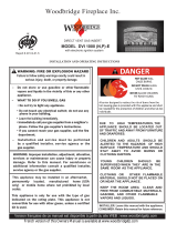
HOT GLASS WILL CAUSE
BURNS
DO NOT TOUCH GLASS
UNTIL COOLED
NEVER ALLOW CHILDREN
TO TOUCH GLASS
A barrier designed to reduce the risk of burns from
the hot viewing glass is provided with this appliance
and shall be installed for the protection of children
and other at-risk individuals.
Tested and Listed by
ANSI Z21.88-2014
CSA 2.33-2014
Direct Vent Fireplace Insert
Masonry or Factory-Built
(Metal) Wood-Burning
Fireplace
Residential or Mobile Home
This appliance may be installed in an aftermarket, permanently located, manufactured home
(USA only) or mobile home, where not prohibited by local codes.
This appliance is only for use with the type of gas indicated on the rating plate. A conversion
kit is supplied with the appliance.
INSTALLER: Leave this manual with the appliance.
CONSUMER: Retain this manual for future reference.
Travis Industries, Inc. 12521 Harbour Reach Dr., Mukilteo, WA 98275 www.travisproducts.com
Copyright 2014, T.I. $10.00 4140811 100-01331

2 Introduction
© Travis Industries 4140811 100-01331
Introduction
We welcome you as a new owner of a 616 GSR2 Diamond-Fyre Insert. In purchasing this fireplace insert
you have joined the growing ranks of concerned individuals whose selection of an energy system reflects
both a concern for the environment and aesthetics. It is one of the finest home heaters the world over.
This manual will explain the installation, operation, and maintenance of this heater. Please familiarize
yourself with the Owner's Manual before operating your heater and save the manual for future reference.
Included are helpful hints and suggestions that will make the operation and maintenance of your new
heater an easier and more enjoyable experience. We offer our continual support and guidance to help
you achieve the maximum benefit and enjoyment from your heater.
Important Information
No other 616 GSR2 Diamond-Fyre Insert has the same
serial number as yours. The serial number is located
below and to the left of the gas control valve.
This serial number will be needed in case you require
service of any type.
Model: 616 GSR2 Diamond-Fyre
Serial Number:
Purchase Date:
Purchased From:
Register your warranty online at:
traviswarranty.com
Save Your Bill of Sale.
To receive full warranty coverage, you will
need to show evidence of the date you
purchased your heater.
We suggest that you attach your Bill of Sale
to this page so that you will have all the
information you need in one place should the
need for service or information occur.
Listing Details
This appliance was listed by Intertek. The listing label is attached to the appliance near the gas control
valve. A copy is shown on page 46.
Massachusetts Approval
This manual has been submitted to the Massachusetts Board of State Examiners of Plumbers and Gas Fitters.
National Fireplace Institute

Table of Contents 3
© Travis Industries 4140811 100-01331
Introduction ...................................................... 2
Important Information ...................................... 2
Listing Details ................................................... 2
Features ............................................................ 6
Installation Options .......................................... 6
Heating Specifications ..................................... 6
Dimensions ....................................................... 6
Electrical Rating ............................................... 6
Fuel .................................................................... 6
Installation Warnings ....................................... 7
Packing List ...................................................... 7
Additional Items Required ............................... 7
Order of Installation ......................................... 7
Fireplace Requirements .................................. 8
Fireplace Clearances to Gas Insert ....................... 8
Factory-Built (Metal) Wood-Burning Fireplace
Requirements ........................................................ 9
Hearth Requirements ....................................... 9
Clearances ...................................................... 10
Mantel Clearances .............................................. 10
Leveling Bolts ................................................. 11
Electrical Requirements ................................ 12
Re-Routing the Power Cord to the Front of the
Insert ................................................................... 12
Using the Insert Wiring Kit................................... 12
Gas Line Requirements ................................. 13
Gas Inlet Pressure .............................................. 13
Directions for Connecting a Gas Pressure Test
Gauge ................................................................. 13
Gas Line Installation ...................................... 14
Vent Requirements ........................................ 15
Altitude Considerations.................................... 15
Exhaust Restrictor ......................................... 16
Adjusting the Exhaust Restrictor ......................... 17
Diffuser Adjustment ....................................... 18
Adjusting the Diffuser .......................................... 18
Vent Installation ............................................. 19
Vent Location ...................................................... 20
Vent Configurations ............................................ 20
Vent Attachment – Tight Installations .................. 21
Vent Connector Attachment ................................ 22
Glass Frame Removal and Installation ........ 25
Steps for Finalizing the Installation ............. 26
Media Tray Removal ........................................... 27
Crushed Glass Installation .................................. 28
Glass Quantity ............................................... 28
Glass Measurement ...................................... 28
Crushed Glass Part Numbers ....................... 28
Crushed Glass Placement ............................. 29
Air Shutter Adjustment ........................................ 30
Before You Begin ........................................... 31
Remote Control Warnings ............................. 31
Remote Set-Up ............................................... 32
Verify the Switch is on “REMOTE” ...................... 32
Synchronize the Transmitter to the IFC ......... 32
Clearing the System Memory ........................ 32
Starting the Heater for the First Time .......... 33
Location of Controls ...................................... 33
Direct Operation ............................................. 33
Continuous/Intermittent Pilot Switch ........... 34
Switching from Intermittent (IPI) to Continuous
Pilot (CPI) ............................................................ 34
Remote Operation .......................................... 35
Display Overview ................................................ 35
Listen for the “Beep” ........................................... 35
Manual On-Off / Smart Thermostat / Standard
Thermostat ........................................................ 36
Mode Controls (Flame, Blower, Light)............. 37
Flame Height ................................................. 37
Blower Speed ................................................ 37
Mode Controls (continued) .............................. 38
Accent Light .................................................. 38
Display Fahrenheit or Celsius ...................... 38
Low Battery Indicator .................................... 39
Transmitter Batteries ........................................... 39
IFC Batteries ....................................................... 39
Battery Replacement ..................................... 39
Battery Installation .............................................. 39
Transmitter Battery Installation ........................... 39
Power Outages ............................................... 39
Child-Proof Feature ....................................... 40
Normal Operating Sounds ............................ 40
Normal Operating Odors ............................... 40
Maintaining Your Heater's Appearance ....... 41
Accent Light(s) Replacement ....................... 41
Upper Accent Light ........................................ 41
Yearly Service Procedure ............................. 43
Troubleshooting Table .................................. 44
Wiring Diagram .............................................. 45
Replacement Parts ........................................ 45
Safety Label ........................................................ 46
CONDITIONS & EXCLUSIONS ...................... 47
IF WARRANTY SERVICE IS NEEDED: ......... 47
LP Conversion Instructions .......................... 48
Packing List ......................................................... 48
Conversion Instructions ...................................... 48

4 Safety Precautions
© Travis Industries 4140811 100-01331
Failure to follow all of the requirements may result in property damage, bodily injury, or even death.
Young children should be carefully supervised when they are in the same room
as the appliance. Toddlers, young children and others may be susceptible to
accidental contact burns. A physical barrier is recommended if there are at risk
individuals in the house. To restrict access to a fireplace or stove, install an
adjustable safety gate to keep toddlers, young children and other at risk
individuals out of the room and away from hot surfaces.
Children and adults should be alerted to the hazards of high surface temperature
and should stay away to avoid burns or clothing ignition. Do not touch the hot
surfaces of the heater. Educate all children of the danger of a high-temperature
heater.
Due to the high temperature, the heater should be located out of traffic and away
from furniture and draperies.
This unit must be installed by a qualified installer to prevent the possibility of an explosion.
This appliance must be installed in accordance with all local codes, if any; if not, in U.S.A. follow ANSI
Z223.1 and NFPA 54(88), in Canada follow CSA B149.1.
A manufactured home (USA only) or mobile home OEM installation must conform with the
Manufactured Home Construction and Safety Standard, Title 24 CFR, Part 3280, or, when such a
standard is not applicable, the Standard for Manufactured Home Installations, ANSI/NCSBCS
A225.1, or Standard for Gas Equipped Recreational Vehicles and Mobile Housing, CSA Z240.4. This
appliance may be installed in Manufactured Housing only after the home is site located.
All exhaust gases must be vented outside the structure of the living-area. Combustion air is drawn
from outside the living-area structure. The venting must not be connected to a chimney flue serving a
separate solid-fuel burning appliance.
Notify your insurance company before hooking up this fireplace.
The instructions in this manual must be strictly adhered to. Do not use makeshift methods or
compromise in the installation. Improper installation will void the warranty and safety listing.
This heater is approved for use with natural gas (NG) or propane (LP). Burning the incorrect fuel will
void the warranty and safety listing and may cause an extreme safety hazard. Direct questions about
the type of fuel used to your dealer.
Contact your local building officials to obtain a permit and information on any installation restrictions
or inspection requirements in your area.
If the flame becomes sooty, dark orange in color, or extremely tall, do not operate the heater. Call
your dealer and arrange for proper servicing.
It is imperative that control compartments, screens, or circulating air passageways of the heater be
kept clean and free of obstructions. These areas provide the air necessary for safe operation.
Do not operate the heater if it is not operating properly in any fashion or if you are uncertain. Call
your dealer for a full explanation of your heater and what to expect.
Do not store or use gasoline or other flammable liquids in the vicinity of this heater.
Do not operate if any portion of the heater was submerged in water or if any corrosion occurs.
Immediately call a qualified service technician to inspect the appliance and to replace any part of the
control system and any gas control which has been under water.

Safety Precautions 5
© Travis Industries 4140811 100-01331
Safety Warnings (continued)
Because this heater can be controlled by a thermostat there is a possibility of the heater turning on
and igniting any items placed on or near the appliance.
Light the heater using the built-in igniter. Do not use matches or any other external device to light
your heater.
Never remove, replace, modify or substitute any part of the heater unless instructions are given in this
manual. All other work must be done by a trained technician. Don't modify or replace orifices.
The viewing glass should be opened only for conducting service.
Allow the heater to cool before carrying out any maintenance or cleaning.
Operate the heater according to the instructions included in this manual.
If the main burners do not start correctly turn the gas off and call your dealer for service.
This unit is not for use with solid fuel.
Do not place anything inside the firebox (except the optional artwork).
Warning: Do not operate appliance with the glass front removed, cracked or broken. Replacement
of the glass should be done by a licensed or qualified service person.
Do not throw this manual away. This manual has important operating and maintenance instructions
that you will need at a later time. Always follow the instructions in this manual.
Instruct everyone in the house how to shut gas off to the appliance and at the gas main shutoff valve.
The gas main shutoff valve is usually next to the gas meter or propane tank and requires a wrench to
shut off.
A barrier designed to reduce the risk of burns from the hot viewing glass is provided with this
appliance and shall be installed for the protection of children and other at-risk individuals.
If the barrier becomes damaged, the barrier shall be replaced with the manufacturer’s barrier for this
appliance.
Clothing or other flammable material should not be placed on or near the appliance.
Any safety screen, guard, or barrier removed for servicing an appliance must be replaced prior to
operating the appliance.
Installation and repair should be done by a qualified service person. The appliance should be
inspected before use and at least annually by a professional service person. More frequent cleaning
might be required due to excessive lint from carpeting, bedding material, et cetera. It is imperative
that control compartments, burners, and circulating air passageways of the appliance be kept clean.
Travis Industries, Inc. grants no warranty, implied or stated, for the installation or
maintenance of your heater, and assumes no responsibility of any consequential damage(s).
Proposition 65 Warning: Fuels used in gas, woodburning or oil fired appliances, and the products of combustion of such
fuels, contain chemicals known to the State of California to cause cancer, birth defects and other reproductive harm.
California Health & Safety Code Sec. 25249.6

6 Features and Specifications
© Travis Industries 4140811 100-01331
Features
- Works During Power Outages (battery backup system)
- Blowers and Remote Control Included
- Continuous or Intermittent (GreenSmart) Pilot
- Convenient Operating Controls
- Variable-Rate Heat Output
- Accent Lights
Installation Options
Residential or Mobile Home
Fireplace Insert
Masonry or Factory Built (Metal) Wood-
Burning Fireplace
Heating Specifications
Natural Gas Propane
Approximate Heating Capacity (in square feet)* 600 to 2,000 600 to 2,000
Maximum BTU Input Per Hour 38,000 35,000
* Heating capacity will vary with floor plan, insulation, and outside temperature.
Dimensions
Electrical Rating
Electrical Rating 120 Volts, 3 Amps, 60 Hz (360 watt)
Fuel This heater is shipped in natural gas (NG) configuration but may be converted to propane (LP) using
the LP Conversion Kit (included) and the LP stepper motor (SKU 94400999, sold separately). The
sticker on top of the gas control valve will verify the correct fuel.
* See "Fireplace Requirements"
for minimum fireplace sizing.
24" *
(610mm) *
16" *
(407mm) *
34" *
(864mm) *
Small 42" (1067mm)
Large 44" (1118mm)
Small 30-1/2"
(775mm)
Large 34"
(864mm)
23-5/16" *
(593mm) *

Installation (for qualified installers only) 7
© Travis Industries 4140811 100-01331
Installation Warnings
Failure to follow all of the requirements may result in property damage, bodily injury, or even death.
This heater must be installed by a qualified installer who has gone through a training program
for the installation of direct vent gas appliances.
The installation must conform with local codes or, in the absence of local codes, the National
Fuel Gas Code, ANSI Z223.1/NFPA 54, or the National Gas and Propane Installation Code, CSA
B149.1.
In Manufactured or Mobile Homes must conform with Manufactured Home Construction and
Safety Standard, Title 24 CFR, Part 3280, or, when such a standard is not applicable, the
Standard for Manufactured Home Installations, ANSI/NCSBCS A225.1. This appliance may be
installed in Manufactured Housing only after the home is site located.
The heater is designed to operate on natural gas, or propane (LP).
All exhaust gases must be vented outside the structure of the living-area. Combustion air is
drawn from outside the living-area structure.
Notify your insurance company before hooking up this heater.
The requirements listed below are divided into sections. All requirements must be met
simultaneously. The order of installation is not rigid – the qualified installer should follow the
procedure best suited for the installation.
Packing List
Propane (LP) Conversion Kit
Remote Control
"Fireplace Altered" tag (attach to the fireplace)
46” Flex Line with Adapter and Shutoff Valve
Additional Items Required
Faceplate
3" and 4” Diameter Gas Liner with Termination (Kit – sku 96200340)
Gas Line Equipment (shutoff valve, pipe, etc.)
Panel Kit
Fireback Kit – metal liners only (sku’s 96100926/96100927/96100928)
Media
If using LP (propane) a conversion kit is required (sku 94400999 – GSR Stepper Motor Kit).
Order of Installation
1. Run gas line to the fireplace.
2. Remove the glass frame.
3. Run vent through fireplace chimney. On larger fireplaces, the vent connector may be left in place. For
smaller fireplaces, remove the vent connector. See “Vent Connector Removal and Installation” for details.
INSTALLATION WARNING: If using an NG tall vent (over 25’) – you must open the
diffuser before attaching the vent. See “Diffuser Adjustment” for details.
INSTALL THE LIGHT SHIELD (ALL FACES EXCEPT SHADOWBOX). The light shield
(shipped with the face) prevents light from exiting the upper grill area. Install this
prior to placing the insert.
4. Place insert into position and attach the gas line and vent.
5. Remove the media tray.
NOTE: If using propane (LP), convert the appliance at this time.
6. Install the firebacks (use one of the following metal firebacks: 96100926, 96100927, or 96100928)
7. Replace the media tray.
8. Install the crushed glass.
9. Install the surround panel (see instructions included with surround panel).
10. Follow the instructions under “Finalizing the Installation.”

8 Installation (for qualified installers only)
© Travis Industries 4140811 100-01331
Fireplace Requirements
The insert must be placed within a code-conforming masonry fireplace or tested and listed factory-
built (metal) wood-burning fireplace. Repair any fireplace damage prior to installation.
Because the insert uses a circulation blower, clean the fireplace, smoke shelf, and chimney prior to
installation.
This heater may be placed in a bedroom. Please be aware of the large amount of heat this appliance
produces when determining a location.
Do not place insulation or any other material on top of the insert. This may block the upper accent
light ventilation, leading to premature bulb failure.
Fireplace Sizing
Minimum Height 24-1/4” (616mm)
Minimum Width 35” (889mm)
Minimum Depth 16-1/2” (420mm)
Hearth Depth (see
“Hearth Requirements”
on the following page
for full details)
12” (305mm)
The gas and electrical line should be installed prior
to installing the heater.
For tight fits (under 28”) see the section
“Removing the Vent Connector”.
See “Leveling Bolts” for details on leveling the
heater.
h Attach the “This fireplace has been altered…” plate to the fireplace (use two screws or other
suitable method). You may wish to place it in a location where it will be covered by the surround
panels.
Fireplace Clearances to Gas Insert
Side of Insert to Inside of Fireplace ½” (13mm)
Back of Insert to Inside of Fireplace ½” (13mm)
Top of Insert to Inside of Fireplace 5/8” (18mm)
a
b
c
e
f
g
d
h
a
b
c
d
e
f
g

Installation (for qualified installers only) 9
© Travis Industries 4140811 100-01331
Factory-Built (Metal) Wood-Burning Fireplace Requirements
NOTE: Any parts that are removed must be removed in a way that will allow them to be re-installed if the
insert is ever removed (removal of rivets or screws is acceptable).
The damper ("A") and grate (with log set) ("B") must be removed (see the illustration below).
The smoke shelf ("C"), internal baffles ("D"), screen ("E"), masonry lining or refractory ("G" & "I"), and
metal or glass doors ("F") may be removed (if applicable).
The fireplace must be permanently marked to
indicate that it has been altered and is no longer
suitable for burning solid fuel (wood), unless the
removed parts are re-installed. Cutting of any
sheet metal parts is prohibited.
The insulation ("H"), and any structured rigid frame
members must not be removed or altered (side and
top of door frame, side and top of the face of the
fireplace, metal sides, etc.).
The metal floor (“J”) of the firebox may be removed
in certain cases*.
The surround panels should not seal ventilation
openings on the fireplace.
*CAUTION: Firebox floor removal is not covered under the appliance safety standard (ANSI Z21.88 CSA 2.33)
used in the safety certification of this appliance. The Intertek safety certification does not apply to this method
of installation. Before installing the appliance using this method, contact the Authority Having Jurisdiction to
determine if this installation is acceptable in your area. The sheet metal base of the fireplace must be left in
place and a minimum ½” cement board sheet placed under the entire length and width of the appliance.
If the factory-built fireplace has no gas access hole(s) provided, an access hole of 1.5 inch (37.5 mm) or
less may be drilled through the lower sides or bottom of the firebox in a proper workmanship like
manner. This access hole must be plugged with non-combustible insulation after the gas supply line has
been installed.
Hearth Requirements
½” of non-combustible material is required underneath the insert.
½” of non-combustible material must extend 12” in front of the insert for the full width of the unit (34”).
RAISED INSERTS: If the insert is raised a minimum of 16” above the flooring (or other combustible
material), a non-combustible hearth is not required in front of the insert.
C
B
F
I
D
E
A
G
H
J

10 Installation (for qualified installers only)
© Travis Industries 4140811 100-01331
Clearances
Due to the high temperature of the heater, it should be located out of traffic and away from furniture and draperies.
Minimum
Clearances
k Sidewall to Insert 6"
153mm
l Side Facing
(non-combustible) 5"
127mm
m Top Facing*
(non-combustible) 35.5"
902mm
n 12” Mantel* (combustible
or non-combustible) 36.5"
928mm
n 4” Mantel* (combustible
or non-combustible) 33"
839mm
p Hearth Extension to the
Front 12"
305mm
x Extension onto Hearth 0"
0mm
* Measured from the base of the insert.
NOTE: The non-combustible top facing must
extend 35.5” (902mm) above the base of the
insert or to the bottom of the mantel (whichever
is less).
Mantel Clearances
The maximum mantel depth is 12” (305mm).
NOTE: The combustible area above the facing must not protrude more than 3/4" (20mm) from the facing.
If it does, it is considered a mantel and must meet the mantel requirements listed in this manual.
Side
Wall
Co
mbustible or Non-C ombus tible Mantel
Comb
ustible Top Facing
Non-Combustible
Facing
l
k
x
n
m
p
Mantel Height
Above Base of Insert (n)
36"(915mm)
35"(889mm)
34"(864mm)
33"(839mm)
37"+(940mm+)
32"(813mm)
31"(788mm)
0"
1" (26mm)
2" (51mm)
8" (204mm)
7" (178mm)
6" (153mm)
5" (127mm)
4" (102mm)
3" (77mm)
9" (229mm)
10" (254mm)
11" (280mm)
12" (305mm)
Maximum Mantel Depth

Installation (for qualified installers only) 11
© Travis Industries 4140811 100-01331
Leveling Bolts
This heater includes front and rear leveling bolts to accommodate fireplaces with a step-down firebox.
NOTE: To access the rear leveling bolts, remove the media tray (see page 27).
The leveling bolt holes are shown below.
1. Remove the cover and gasket to access the rear leveling bolt (7/16” Socket Wrench). Replace after
adjustment.

12 Installation (for qualified installers only)
© Travis Industries 4140811 100-01331
Electrical Requirements
Travis Industries manufactures a wiring kit specifically for inserts (sku 97200315). This kit allows installers to
wire 120 volt AC power into a fireplace directly to the insert, eliminating the need for an external power cord.
Plug the power cord into a grounded 120 Volt outlet (do not remove the grounding pin).
The appliance, when installed, must be electrically grounded in accordance with local codes or, in the
absence of local codes, with the National Electrical Code, ANSI/NFPA 70, or the Canadian Electrical
Code, CSA C22.1.
Do not route the power over the appliance or near any hot or moving components.
Re-Routing the Power Cord to the Front of the Insert
The power cord is shipped attached to the side of the insert. It may be routed to the front where it exits
behind the face but in front of the surround panel. See the directions below for details.
Using the Insert Wiring Kit
When using the insert wiring kit, remove and discard the cover plate on the side of the insert. See the
instructions included with the wiring kit for attaching the kit to the side of the insert.
Power Cord
Remove the side
access panel.
Use pliers to remove
the strain relief.
Disconnect the molex connector and remove
the power cord from of the side location.
Re-attach the strain relief and power cord
to the forward location and re-connect
the molex connector.
a
b
c
d
Disconnect the molex connection
and remove the power cord.
cd
Remove and discard the cover plate.
The wiring kit connects to the larger
hole on side of the insert
Power Cord
Remove the side
access panel.
Use pliers to
remove the
strain relief.
a
b

Installation (for qualified installers only) 13
© Travis Industries 4140811 100-01331
Gas Line Requirements
MASSACHUSETTS INSTALLATIONS - WARNING:
THIS PRODUCT MUST BE INSTALLED BY A LICENSED PLUMBER OR GAS FITTER WHEN INSTALLED WITHIN THE
COMMONWEALTH OF MASSACHUSETTS.
OTHER MASSACHUSETTS CODE REQUIREMENTS:
Flexible connector must not be longer than 36 inches.
Shutoff valve must be a “T” handle gas cock.
Only direct vent sealed combustion products are approved for bedrooms or bathrooms.
Fireplace dampers must be removed or welded in the open position prior to the installation of a fireplace insert or gas log.
A carbon monoxide (CO) detector is required in the same room as the appliance.
The gas line must be installed in accordance with all local codes, if any; if not, follow ANSI 223.1 and
the requirements listed below.
A manual shutoff valve is required within 3’ of the heater. It should be placed upstream of the flex line
(if used) and may be installed behind the access door inside the heater.
The heater and gas control valve must be disconnected from the gas supply piping during any
pressure testing of that system at test pressures in excess of 1/2 psig. For pressures under 1/2 psig,
isolate the gas supply piping by closing the manual shutoff valve.
Leak test all gas line joints and the gas control valve prior to and after starting the heater.
This heater is designed either for natural gas or for propane (but not for both). Check the sticker on
the top of the gas control valve to make sure the correct fuel is used (see illustration on page 4).
Installation must be performed by a qualified installer, service agency or the gas supplier (In
Massachusetts a licensed plumber/gas-fitter).
Gas Inlet Pressure
Gas Pressure
Max. Input Pressure Min. Input Pressure Max. Manifold Pressure Min. Manifold Pressure
Natural Gas
7" W.C. (1.74 kPA) 5.5” W.C. (1.37 kPA) 3.8” W.C. (0.95 kPA) 1.1” W.C. (0.27 kPA)
Propane
13" W.C. (3.23 kPA) 11” W.C. (2.74 kPA) 11” W.C. (2.74 kPA) 2.9” W.C. (0.72 kPA)
If the pressure is not sufficient, make sure the piping used is large enough, the supply regulator is
adequately adjusted, and the total gas load for the residence does not exceed the amount supplied.
The supply regulator (the regulator that attaches directly to the residence inlet or to the propane tank)
should supply gas at the suggested input pressure listed above. Contact the local gas supplier if the
regulator is at an improper pressure.

14 Installation (for qualified installers only)
© Travis Industries 4140811 100-01331
Gas Line Installation
1. Route the included flex tube through the hole in the left side of the insert and out the front as shown below.
2. Bend the flex tube up.
3. Attach the included gas shutoff valve to the end of the flex tube and gas inlet as shown below.
Position so the valve handle is on the right as shown.
Leak-test all gas line connections.

Installation (for qualified installers only) 15
© Travis Industries 4140811 100-01331
Vent Requirements
Travis Industries manufactures a vent kit
specifically for this insert (sku 96200340).
Includes 30’ (10M) of vent, hose clamps,
and a high wind cap. The flashing on the
cap is 18” (458mm) by 18” (458mm).
The gas appliance and vent system must be vented directly to the outside of the building, and never
be attached to a chimney serving a separate solid fuel or gas-burning appliance. Each direct vent
gas appliance must use its own separate vent system.
Make sure the exhaust pipe on the heater connects to the exhaust portion of the cap. The
illustrations below show how the flex liners should be attached.
The exhaust vent must reline the entire length of the chimney and terminate above the chimney top.
Be careful not to crimp or rupture the liner when bending it into chimney offsets.
When installed, the vent must meet all of the vent manufacturer's requirements.
Use the following vent:
4” UL 441 or 1777 Gas Liner for Exhaust, 3” UL 441 or 1777 Gas Liner for Air Inlet
Duravent 6-5/8” to 3” & 4” Co-Linear Adapter and Flashing (Travis Part # 98900124).
Duravent High-Wind Vertical Termination (46DVA-VCH) for high-wind applications
Altitude Considerations
This heater has been tested at altitudes ranging from sea level to 6,000 feet (1,800 M). In this testing we
have found that the heater, with its standard orifice, burns correctly with just an air shutter adjustment.
Failure to adjust the air shutter properly may lead to improper combustion which can create a safety
hazard. Consult your dealer or installer if you suspect an improperly adjusted air shutter.
M
ax. Ht. 40' (12.2M)
M
in. Ht. 8' (2.5M)
Exhaust
Max. 2'
(610mm)
offset
Inlet
Exhaust
(4
”
dia.)
Inlet
(3
”
dia.)

16 Installation (for qualified installers only)
© Travis Industries 4140811 100-01331
Exhaust Restrictor
Set the exhaust restrictor to the position shown in the table below.
NOTE: The appliance will slow down within 5 to 10 minutes of startup due to the bi-metallic damper
closing. Make sure to wait for at least 10 minutes before assessing flame quality.
NOTE: The restrictor positions listed below are based upon laboratory testing. The optimum position may
vary slightly.
Natural Gas
(NG)
Height Position
Propane
(LP)
Height Position
15’ or less Removed* 15’ or less Removed*
15’ – 25’ #2 (Stock) 15’ – 25’ #2 (Stock)
25’ – 35’ #3 25’ – 40’ #3
35’ – 40’ #4
* If removing the restrictor, replace the screws into the holes in the firebox ceiling. Place the restrictor
plate near the appliance (in fireplace cavity) so it may be used at a later time if needed.
Restrictor adjustment should only be done by a qualified installer.

Installation (for qualified installers only) 17
© Travis Industries 4140811 100-01331
Adjusting the Exhaust Restrictor
1. With a ¼” nutdriver, loosen the 4 screws holding the exhaust restrictor in place.
2. Slide the exhaust restrictor to the desired position. The photos above show the exhaust restrictor in
position #3.

18 Installation (for qualified installers only)
© Travis Industries 4140811 100-01331
Diffuser Adjustment
Adjusting the Diffuser
Adjust the diffuser to the setting described in the table below.
Diffuser
Natural Gas Short Vent
(25’ or less)
Closed (stock)
Natural Gas Tall Vent
(25’ or more)
Open
Propane – all vents Closed (stock)
The diffuser must be adjusted before attaching the vent (it is attached to the vent connector and is
concealed once the vent is installed). Use a screwdriver or pliers to bend the diffuser to a vertical position.

Installation (for qualified installers only) 19
© Travis Industries 4140811 100-01331
Vent Installation
Secure the vent to the insert and termination kit using screws.
For optimum performance, keep the vent as straight as possible (no 90 bends).
Inlet (3" 76mm)
Exhaust (4" 102mm)
Inlet
Exhaust
3" (76mm) dia.
4" (102mm) dia. Additional Coaxial
Sections May Be Added
(support as needed)
Approved
Cap

20 Finalizing the Installation
© Travis Industries 4140811 100-01331
Vent Location
An Exhaust Restrictor is built into the appliance to adjust the flow rate of exhaust gases. This
ensures proper combustion for all vent configurations. Depending upon the vent configuration, you
may be required to adjust the restrictor position. See “Exhaust Restrictor” on page 16.
Vent Configurations
Inlet
Z.C. (Metal) Wood-Burning Fireplace
Inlet & Exhaust Re-Line
(recommended) Exhaust Only Re-Line
(not recommended)
Direct Vent Cap
Recommended Block-Off
Plate (non-combustible
metal and/or insulation).
Prevents odors from
chimney entering room.
6-5/8" to 3" & 4" Colinear
Adapter & Flashing
A block-off plate must
seal the intake to the
chimney space. This
way air is drawn down
the chimney for
combustion air.
Block-Off Plate
(non-combustible
materials)
NOTE: You may use either re-line configuration with a masonry or zero-clearance fireplace.
Inlet
Masonry Fireplace
Any cracks or
damage inside the
chimney must be
repaired.
Exhaust Exhaust
/