Makita EW1050H Datasheet

Category
Power tools
Type
Datasheet

Makita EW1050H is a 24.5cc 4-stroke engine pump designed to tackle various water-related tasks efficiently. With its impressive 35 meters (115 feet) maximum total head and 110 liters (3,700 ounces) per minute maximum pumping capacity, it can move large volumes of water quickly and effectively. Whether you need to drain a flooded basement, water your garden, or transfer water from one place to another, this pump is up to the challenge.

Makita EW1050H is a 24.5cc 4-stroke engine pump designed to tackle various water-related tasks efficiently. With its impressive 35 meters (115 feet) maximum total head and 110 liters (3,700 ounces) per minute maximum pumping capacity, it can move large volumes of water quickly and effectively. Whether you need to drain a flooded basement, water your garden, or transfer water from one place to another, this pump is up to the challenge.

PRODUCT
CONCEPT AND MAIN APPLICATIONS
P 1/ 10
Specification
Standard equipment
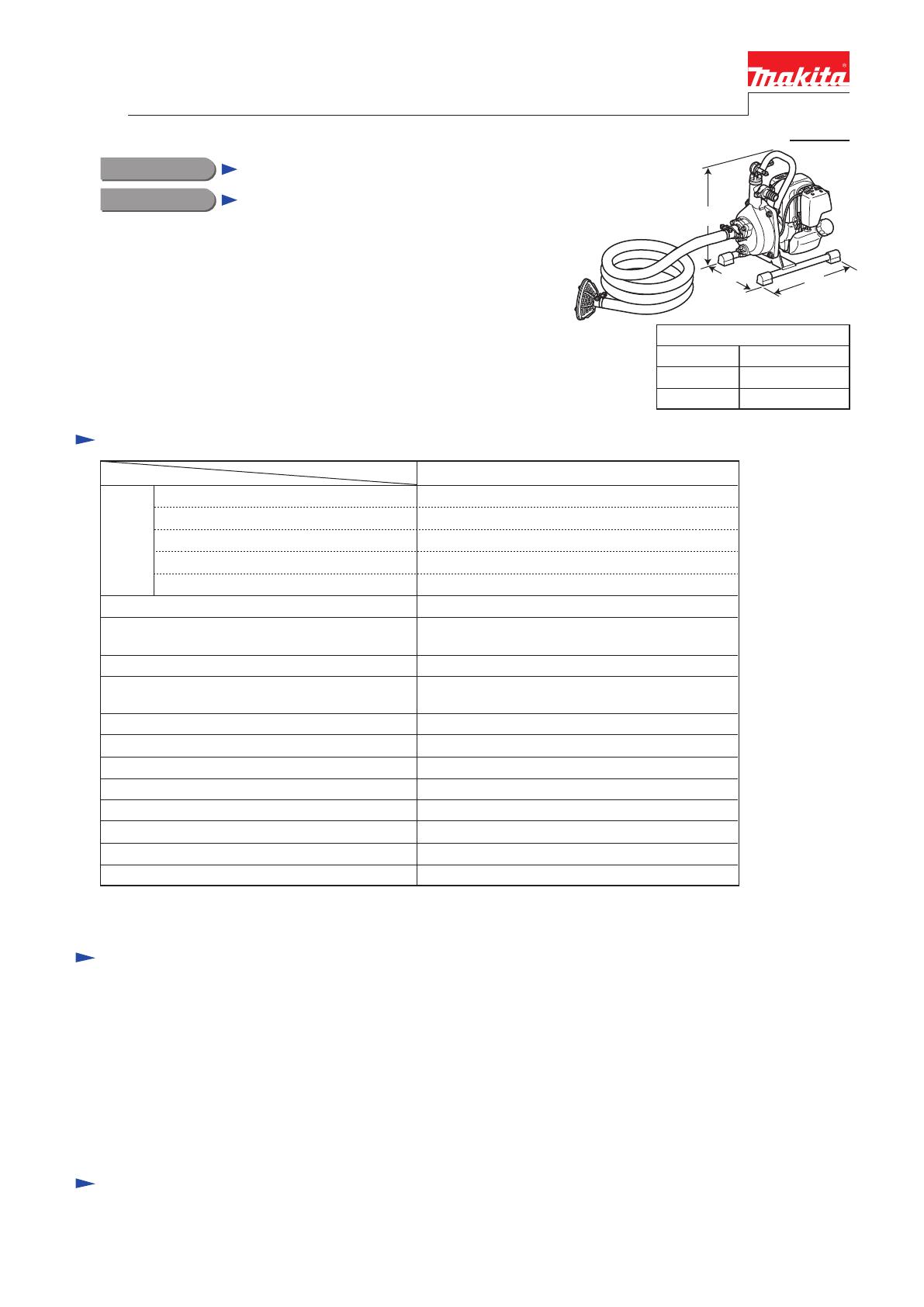
Note: The standard equipment for the tool shown above may vary by country.
Model No. EW1050H
Description Engine Pump
Model EW1050H is 24.5cc 4-stroke engine pump to comply with
all major exhaust emission regulations in the world.
It features the same pumping capacity as the predecessor EW120R,
but it is more cost effective than EW120R.
This product is also available with nozzle and 8m delivery hose
as Model EW1050HX.
Optional accessories
Suction hose .......................... 1
Socket wrench ....................... 1
Hose coupling ....................... 2 (for some countries only)
Rapid type hose coupling ...... 2 (for some countries only)
1 inch NPT adapter ............... 1 (for Canada, Mexico, Colombia, Chile, Peru and Brazil only)
Hose band ............................. 3
Strainer ................................. 1
Delivery hose (8m) ............... 1 (for EW1050HX only)
Nozzle ................................... 1 (for EW1050HX only)
Rapid type Hose coupling set
Coupling for water supply hose (with Hose band)
8m Delivery hose (with Nozzle)
1 inch NPT adapter
Straight unleaded gasoline*2
Carburetor
Engine
Displacement: cm³ (cu.in.)
Fuel
Specifications Model
Type
Net weight*3: kg (lbs)
*2 Brazil: 25E gasoline
*3 Dry weight, without suction hose
EW1050H
In compliance with exhaust emission regulations:
CARB Tier 3, EPA Phase 2, EU Stage 2
Starting system
Max. suction head: m (ft)
Max. output: kW (PS)
Diaphragm
Suction & discharge diameter: mm (") 25.4 (1)
24.5 (1.5)
4-stroke
8.0 (26)
Max. pumping capacity: L/min (US oz/min) 110 (3,700)
Primer pump Yes
Yes
5.8 (12.8)
0.71 (1.0) [at 7,000 min.ˉ¹]
1.0 [at 5,500 min.ˉ¹]Max. torque: N·m
Speed at no load: min.ˉ¹ = rpm 7,000
Recoil starter, with mechanical decompression
Max. total head: m (ft) 35 (115)
Fuel tank capacity: L (US oz)
Engine oil
0.5 (16.9)
SAE10W-30 oil
in the class SF or higher of API Classification
231 (9-1/8)
Dimensions*1: mm (")
Width (W)
Height (H)
Length (L) 327 (12-7/8)
319 (12-1/2)
*1 without suction hose
TECHNICAL INFORMATION
L
H
W
P 2/ 10
Repair
[3] DISASSEMBLY/ASSEMBLY
[3] -1. Pump Section
DISASSEMBLING
Shelf group Shelf group
M8x30 Hex bolt
Remove Handle by unscrewing M8 Hex nut
while holding M8x30 Hex bolt with Wrench 8.
Remove Shelf group by unscrewing
M8 Hex nut while holding M8x30
Hex bolt with Wrench 8.
M8 Hex nut
Pump case
Remove Pump casing, and then, separate Volute from Engine section.
Pump frame
Pump frame
Pump case
Pump case
Pump frame
Starter rope
M8x30 Hex bolt
Handle
M8 Hex nut
Handle
(1) Remove M8 Hex nut ( 4 pcs. in total) in order to separate Pump case and Shelf group from Engine section.
And disassemble Pump frame and Volute as drawn in Fig. 1.
Pump casing Volute
Fig. 1
P 3/ 10
Repair
Air cleaner cover
Refueling winding
1. Remove Air cleaner cover by unscrewing M5x14 Pan head screw.
Then remove Refueling winding from Carburetor.
2. While sliding down Sheath of Refueling winding
to expose the inner cable, remove the stopper from
Refueling handle group along the curve.
M5x14 Pan head screw
3. Remove Pan head screw and separate Refueling handle group
from Handle.
Sheath of Refueling winding
Stopper of Refueling winding
Refueling handle group
Refueling handle
group
Curve
(2) Remove Refueling winding from Refueling handle group and from Carburetor as drawn in Fig. 2.
Fig. 2
Refueling winding
[3] DISASSEMBLY/ASSEMBLY
[3] -1. Pump Section (cont.)
DISASSEMBLING
Pan head screw
P 4/ 10
Repair
1. After removing Spark plug, drive 1R372 to
the place where Spark plug was mounted.
2. Turn Impeller slowly counterclockwise
until Piston is locked.
5. Using a slotted screwdriver, remove
Mechanical oil seal (on rear side) from
Pump frame.
Note: Mechanical oil seals (on front and rear sides)
have to be replaced as a set.
4. After removing Washers (0.5mm and 0.2mm),
unscrew four M5x25 Hex bolts to remove
Pump frame from Engine section.
3. Apply 1R090 to the rib (Fin) of Impeller, then turn
Impeller counterclockwise by tapping 1R090 with
a hammer to remove Impeller from Pump frame.
And then, remove Mechanical oil seal (on front side)
from Impeller using a slotted screwdriver.
Mechanical oil seal
(rear side)
Pump frame
(3) Disassemble Impeller and Pump frame as drawn in Fig. 3.
Washers (0.5mm and 0.2mm)
M5x25 Hex bolt (4 pcs.)
Mechanical oil seal
(on front side)
1R090
Fig. 3
1R372
[3] DISASSEMBLY/ASSEMBLY
[3] -1. Pump Section (cont.)
DISASSEMBLING
P 5/ 10
Repair
ASSEMBLING
1. When the lever of Refueling handle group is fully
turned to Lowest speed position, “L” mark has to be
precisely aligned to the notch.
If not, loosen Pan head screw and adjust it so that
“L” comes exactly to the notch.
1. Assemble O ring to the groove of
Pump frame.
2. Assemble Mechanical oil seal (rear) to Pump frame by pressing it
straight with Arbor press until it stops.
3. Assemble Mechanical oil seal (front) to Impeller by pressing it
straight with Arbor press until it stops.
Note: Mechanical oil seals (front and rear sides) have to be replaced
as a set.
2. Assemble Refueling handle group to Handle with
Pan head screw.
Note: The fastening torque is 2.5 ~ 3.5 N.m.
And make sure that the mounted Refueling
handle group does not wobble on the Handle.
(1) Assemble Refueling handle group to Handle as drawn in Fig. 4.
(2) Assemble Mechanical oil seals to Pump body (rear) and to Impeller as drawn in Fig. 5.
(3) Assemble Water blocks, Valve and Joint to Pump casing as drawn in Fig. 6.
Water block
1. Install O-rings to Water blocks.
2. Tighten Water block
to the top side of
Pump casing
by hand.
3. Mount Water block to the bottom side of Pump casing.
Note: This block has to be tightened to 2.5 N.m fastening
torque.
O-ring
Notch
Fig. 4
Fig. 5
Fig. 6
“H”
“L”
Pan head screw
O ring
Pump frame
Pan head screw
4. Put Valve on the suction hole of Pump casing,
then while facing the arrow mark of Joint to
Water block of Shelf group side, put it on Valve
and tighten them with three M6x20 Hex bolts.
Arrow mark
Valve
Pump casing
Joint
[3] DISASSEMBLY/ASSEMBLY
[3] -1. Pump Section (cont.)
Mechanical oil seal (rear)
Mechanical oil seal (front)
Impeller
P 6/ 10
Repair
(4) Assemble Pump frame as drawn in Fig. 7.
(4A) In case of replacing the Engine, adjust the length of Engine’s drive shaft as drawn in Fig. 8 before mounting Pump
frame to the Engine.
Fig. 7
Fig. 8
O ring
Wad (Wave washer) Gasket (Flat washer)
M5x25 Hex bolt
1. Pass each M5x25 Hex bolt through
Wave washer, Flat washer and O ring.
Note: Be careful not to give damage to O ring
when mounting it to the bolt.
2. Mount one each of Washers (0.5mm thick and 0.2mm thick) to Drive shaft of the Engine.
Then assemble Pump frame to the Engine by tightening it with four M5x25 Hex bolts.
Note: Fastening torque of their bolts have to be 2.5 -3.5 N.m.
Washers (0.5mm thick
and 0.2mm thick)
Drive shaft
1A. Measure the length from the stepped portion of
Drive shaft to the neck of the Engine.
If the length is between 27.4 to 29mm, mount
Pump frame to the Engine without Washer(s)
as drawn in Fig. 7.
2A. If the length is shorter than 27.4 mm, adjust
the length to 27.4 ~ 29mm by adding some
Washer(s) as drawn below. Then mount Pump
frame to the Engine as drawn in Fig. 7.
Note: Use Washers (0.5mm thick and 0.2mm thick)
when adjusting the length.
Pump frame
M5x25
Hex bolt
(4 pcs.)
Engine
27.4 ~ 29 mm
Engine
27.4 ~ 29 mm
Washer(s)
Drive shaft
Drive shaft
In case of replacing the Engine
In case of repairing of Pump section without replacing the Engine
ASSEMBLING
[3] DISASSEMBLY/ASSEMBLY
[3] -1. Pump Section (cont.)
P 7/ 10
Repair
(5) Assemble Impeller and Volute to Pump frame as drawn in Fig. 9.
(6) Assemble Pump casing and Handle to Pump body (rear) as drawn in Fig. 10.
Fig.9
Fig.10
1. To Pump frame, assemble Pump casing and Handle
with M8x35 Hex bolt, Flat washer, Wave washer
and M8 Hex nuts.
Impeller
1. Mount Impeller to the drive shaft of the Engine
by turning it clockwise until it is seated on.
Accepting ribs
2. Assemble Volute to Pump frame while fitting its projections to the accepting ribs
on Pump frame. Then put Packing to the Volute.
Projection
M8x35 Hex bolt
M8x35 Hex bolt
Handle
M8 Hex nut
M8 Hex nuts
Flat gaskets
(Flat washers)
Wads
(Wave washers)
Flat gasket
(Flat washer)
Wad (Wave washer)
Projection
Volute
Volute
Packing
Pump frame
Pump casing
Pump casing
Pump frame
Handle
ASSEMBLING
[3] DISASSEMBLY/ASSEMBLY
[3] -1. Pump Section (cont.)
Pump frame
2. Tighten M8x35 Hex bolt and M8 Hex nut
to 13 N.m fastening torque.
Note: The joint of Pump frame and
Pump casing has to be flat.
P 8/ 10
Repair
(7) Assemble Shelf group as drawn in Fig. 11,
and check the condition of Impeller, in case of replacing the Engine to the new one.
Fig. 11
In case of replacing the Engine to the new one
M8 Hex nuts
1. Make sure that the fuel is removed completely from the Engine.
2. Switch off.
3. Pull Recoil starter in order to make sure that the rotating Impeller does not touch Volute.
In case of touching Volute, return to Fig. 8, and adjust by adding or reducing Washer(s).
Shelf group
1. Assemble Shelf group to the machine
with M8x35 Hex bolt, Flat washer
Wave washer and M8 Hex nuts.
M8x35
Hex bolts
2. Tighten M8x35 Hex bolt and M8 Hex nut
to 13 N.m fastening torque.
ASSEMBLING
[3] DISASSEMBLY/ASSEMBLY
[3] -1. Pump Section (cont.)
Flat gaskets
(Flat washers)
Wads
(Wave washers)
P 9/ 10
Repair
(8) Assemble Refueling winding to Refueling handle group as drawn in Fig. 12.
(9) Assemble Refueling winding to Throttle lever of Carburetor as drawn in Fig. 13.
Fig. 12
Fig. 13
Curve
Groove
Stopper
Sheath
Refueling handle group
1. Align the hole for Stopper of Refueling winding
to the curve of Refueling handle group.
2. Insert Stopper of Refueling winding
into the hole along the curve.
3. Put the inner cable of Refueling winding
into the groove of Refueling handle group.
4. Connect the sheath of Refueling winding
to the original position of Refueling handle
group.
5. Guide the other end of Refueling
winding to Carburetor side by passing
it under Pump frame.
1. Connect the other end of Refueling winding to Carburetor. Then align the lever of
Refueling handle group to “L” position. And then make sure that Adjusting screw of
Carburetor is contacted to Throttle lever of Carburetor.
If the screw is not connected to the lever, regulate Adjust screw until Adjusting screw
of Carburetor contacts Throttle lever of Carburetor.
Pump frame
Adjust screw
2. Assemble Air cleaner cover with M5x14 Pan head screw.
Air cleaner cover
ASSEMBLING
[3] DISASSEMBLY/ASSEMBLY
[3] -1. Pump Section (cont.)
Adjusting screw of Carburetor comes
in contact with Throttle lever of
Carburetor at “L” position of
Refueling handle group.
P 10/ 10
Repair
[3] DISASSEMBLY/ASSEMBLY
[3] -2. Difference between Engine EH025P for EW1050H and EH025 for Brush cutters
EH025P is different from EH025 as drawn in Fig. 14.
After removing Blower housing, separate two M6x16 Pan head screws and Shaft from Flywheel. The other disassembly/
assembly is the same as Makita brush cutters
Fig. 14
Parts breakdown of Engine section
Shaft section
Flywheel
Clutch section
(EH025 only)
Shaft section
(EH025P only)
M6x16 Pan head
screw (2 pcs.)
Shaft
Oil tube
(EH025 only)
43
Blower housing
1 / 1

Makita EW1050H Datasheet

Category
Power tools
Type
Datasheet

Makita EW1050H is a 24.5cc 4-stroke engine pump designed to tackle various water-related tasks efficiently. With its impressive 35 meters (115 feet) maximum total head and 110 liters (3,700 ounces) per minute maximum pumping capacity, it can move large volumes of water quickly and effectively. Whether you need to drain a flooded basement, water your garden, or transfer water from one place to another, this pump is up to the challenge.

Ask a question and I''ll find the answer in the document

Finding information in a document is now easier with AI

Ask the document