
Service Manual
Microwave Oven, Convection & Grill
KOC-1B5K
SEP. 2008

1
PRECAUTIONS TO BE OBSERVED BEFORE AND
DURING SERVICING TO AVOID POSSIBLE
EXPOSURE TO EXCESSIVE MICROWAVE ENERGY
(a) Do not operate or allow the oven to be operated with the door open.
(b) Make the following safety checks on all ovens to be serviced before activating the magnetron or other
microwave source, and make repairs if necessary: (1) Interlock operation, (2) Proper door closing, (3)
Seal and sealing surfaces (arcing, wear, and other damage), (4) Damage to or loosening of hinges
and latches (5) Evidence of dropping or abuse.
(c) Before turning on power to the microwave oven for any service test or inspection within the microwave
generating compartments, check the magnetron, wave guide or transmission line, and cavity for proper
alignment, integrity, and connections.
(d) Any defective or misadjusted components in the interlock, monitor, door seal and microwave
generation and transmission systems shall be repaired, replaced, or adjusted by procedures described
in this manual before the oven is released to the owner.
(e) A microwave leakage check to verify compliance with the Federal performance standard should be
performed on each oven prior to release to the owner.
TABLE OF CONTENTS
1. SAFETY AND PRECAUTIONS....................................................................................................................................2
2. SPECIFICATIONS ........................................................................................................................................................3
3. EXTERNAL VIEW.........................................................................................................................................................3
3-1. OUTER DIMENSION..........................................................................................................................................3
3-2. FEATURE DIAGRAM .........................................................................................................................................4
4. INSTALLATION ............................................................................................................................................................5
5. CONTROL PANEL .......................................................................................................................................................6
6. DISASSEMBLY AND ASSEMBLY..............................................................................................................................7
7. INTERLOCK MECHANISM AND ADJUSTMENT.......................................................................................................18
8. TROUBLESHOOTING GUIDE.....................................................................................................................................19
9. MESUREMENT AND TEST .........................................................................................................................................25
9-1. MEASUREMENT OF THE MICROWAVE POWER OUTPUT ........................................................................25
9-2. MICROWAVE RADIATION TEST ....................................................................................................................26
9-3. COMPONENT TEST PROCEDURE................................................................................................................27
9-4. COMPONENT ACTION....................................................................................................................................28
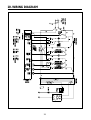
10. WIRING DIAGRAM...................................................................................................................................................29
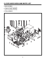
11. EXPLODED VIEW AND PARTS LIST ..................................................................................................................30
11-1. DOOR ASSEMBLY.........................................................................................................................................30
11-2. CONTROL PANEL ASSEMBLY.....................................................................................................................30
11-3. TOTAL ASSEMBLY........................................................................................................................................30
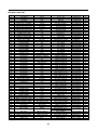
12. PRINTED CIRCUIT BOARD ....................................................................................................................................33
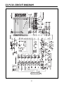
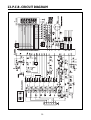
13. P.C.B CIRCUIT DIAGRAM.......................................................................................................................................37

2
1. PROPER USE AND SERVICE PRECAUTIONS
1. FOR SAFE OPERATION
Damage that allows the microwave energy (that cooks or heats the food) to escape will result in poor cooking and may
cause serious bodily injury to the operator.
IF ANY OF THE FOLLOWING CONDITIONS EXIST, OPERATOR MUST NOT USE THE APPLIANCE. (Only a trained
service personnel should make repairs.)
1) A broken door hinge.
2) A broken door viewing screen.
3) A broken front panel, oven cavity.
4) A loosened door lock.
5) A broken door lock.
The door gasket plate and oven cavity surface should be kept clean.
No grease, soil or spatter should be allowed to build up on these surfaces or inside the oven.
DO NOT ATTEMPT TO OPERATE THIS APPLIANCE WITH THE DOOR OPEN.
The microwave oven has concealed switches to make sure the power is turned off when the door is opened.
Do not attempt to defeat them.
DO NOT ATTEMPT TO SERVICE THIS APPLIANCE UNTIL YOU HAVE READ THIS SERVICE MANUAL.
2. FOR SAFE SERVICE PROCEDURES.
1. If the oven is operative prior to servicing, a microwave emission check should be performed prior to servicing the
oven.
2. If any certified oven unit is found to servicing, a microwave emission check should be performed prior to servicing the
oven.
(a) inform the manufacturer, importer or assembler,
(b) repair the unit at no cost to the owner,
(c) attempt to ascertain the cause of the excessive leakage,
(d) tell the owner of the unit not to use the unit until the oven has been brought into compliance.
3. If the oven operates with the door open, the service person should tell the user not to operate the oven and contact
the manufacturer immediately.
CAUTION
MICROWAVE RADIATION
PERSONNEL SHOULD NOT BE EXPOSED TO THE MICROWAVE ENERGY WHICH MAY RADIATE
FROM THE MAGNETRON OR OTHER MICROWAVE GENERATING DEVICE IF IT IS IMPROPERLY
USED OR CONNECTED. ALL INPUT AND OUTPUT MICROWAVE CONNECTIONS. WAVEGUIDES
FLANGES AND GASKETS MUST BE SECURED. NEVER OPERATE THE DEVICE WITHOUT A
MICROWAVE ENERGY ABSORBING LOAD ATTACHED. NEVER LOOK INTO AN OPEN WAVEGUIDE OR
ANTENNA WHILE THE DEVICE IS ENERGIZED.
CAUTION
This device is to be Serviced only by Properly Qualified Service Personel. Consult the Service Manual for Proper
Service Procedures to Assure Continued Safety Operation and for Precautions to be Taken to Avoid Possible
Exposure to Excessive Microwave Energy.

3
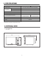
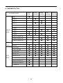
2. SPECIFICATIONS
MODEL
POWER SUPPLY 120V AC 60Hz, SINGLE PHASE WITH GROUNDING
POWER CONSUMPTION 1500W
MICROWAVE OUT POWER 1000W
FREQUENCY 2450 MHz
GRILL POWER CONSUMPTION 1600W
CONVECTION POWER CONSUMPTION 1600W
COMBINATION HEATING POWER CONSUMPTION 1600W
OUTSIDE DIMENSIONS (WXHXD)
CAVITY DIMENSIONS (WXHXD) 368.5X376.5X246mm 14.5X14.8X9.7inch
NET WEIGHT Approx. 20.5kg(45.2 lbs.)
TIMER 60 minutes
POWER SELECTIONS 10 level
KOC-1B0K9A27,1B4K9A27
560X543X344mm
(22.0X21.3X13.5inch)
KOC-1B5K9A27
560X537.5X344mm
(22.0X21.2X13.5inch)
* Specifications are subject to change without notice.
3. EXTERNAL VIEW
3-1. OUTER DIMENSION
- KOC-1B5K
560
344
537.5

4
1. DOOR SEAL
Door seal maintains the microwave energy within the oven cavity and prevents microwave leakage.
2. DOOR HOOK
When the door is closed, it will automatically lock shut. If door is opened while oven is operating, the
magnetron will immediately stop operating.
3. DOOR VIEWING SCREEN
Allows viewing of food. The screen is designed so that light can pass through, but not the microwave.
4. TOP HEATER
Turns on when convection, grill and combi cooking is selected.
5. OVEN LAMP
Automatically turns on during oven operating.
6. SAFETY INTERLOCK SYSTEM
7. CONTROL PANEL
8. TURNTABLE TRAY
Rotates during cooking and ensure even distribution of Microwaves. It can also be used as a cooking utensil.
9. OVEN FRONT PLATE
10. COUPLER
This fits over the shaft in the center of the ovens cavity floor. This is to remain in the oven for all cooking.
11. ROLLER GUIDE
This must always be used for cooking together with the turntable tray.
12. METAL RACK
13. CONVECTION OUTLET & FAN
14. UNDER HEATER
2. FEATURE DIAGRAM

5
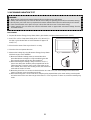
1. Steady, flat location
This microwave oven should be set on a steady, flat surface.
This microwave oven is designed for counter top use only.
2. Leave space behind and side
All air vents should be kept a clearance. If all vents are covered during operation, the oven may overheat and, eventually,
cause failure.
3. Away from Radio and TV sets
Poor television reception and radio interference may result if the oven is located close to a TV, Radio, antenna or feeder
and so on.
Position the oven as far from them as possible.
4. Away from heating appliances and water taps
Keep the oven away from hot air, steam or splash when choosing a place to position it, or the insulation might be
adversely affected and breakdowns occur.
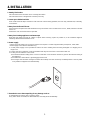
5. Power supply
• Check your local power source. This microwave oven requires a current of approximately 13 amperes, 120V, 60Hz.
• Power supply cord is about 0.8 meters long.
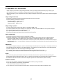
1. A short power-supply cord is provided to reduce the risks resulting from becoming entangled in or tripping over a
longer cord.
2. Longer cord sets or extension cords are available and may be used if care is exercised in their use.
3. If a long cord or extension cord is used:
1) The marked electrical rating of the cord set or extension cord should be at least as great as the electrical rating of
the appliance.
2) The extension cord must be a grounding type 3-wire cord.
3) The longer cord should be arranged so that it will not drape over the counter top or tabletop where it can be pulled
on by children or tripped over unintentionally.
7. Examine the oven after unpacking for any damage such as:
A misaligned door, broken door or a dent in cavity.
If any of the above are visible, DO NOT INSTALL, and notify dealer immediately.
4. INSTALLATION

6
%
17
0
e
s
d
t
u
8
9
2
3
4
q
f
r
y
g
a
w
p
o
i
5
6
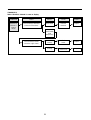
DISPLAY WINDOW (INDICATOR)
1. MICROWAVE indicator: show microwave cook in
progress.
2. DEFROST indicator: show defrost cook in progress.
3. GRILL(upper grill heater) indicator: show grill cook
in progress.
4. GRILL(lower grill heater) indicator: show grill cook in
progress.
5. CONVECTION indicator: show convection cook in
progress.
6. CHILD LOCK indicator.
7. % percentage microwave power level indicator.
BUTTONS
8. Memory : Use to set favorite cooking mode.
9. Language : Press to select the language.
10. Clock : Use to set the clock.
11. Crusty : Press to select crusty menu.
12. Auto cook : Press to select auto cook menu.
13. Cake : Press to select cake menu.
14. More : Use to add time to cooking.
15. Less : Use to reduce time from cooking.
16. Stop/Clear : Press once to stop a program, and
twice to cancel a program.
17. Start/Speedy Cook : Press to start a program, also
for speedy cook (each press adds 30 seconds to
microwave cooking time).
18. Dial knob button : Use to decied the selected
mode.
DISPLAY LED LAMP
19. M/W LED LAMP: show microwave cook in
progress.
20. AUTODEFROST LED LAMP: show auto defrost
cook in progress.
21. GRILL LED LAMP: show grill cook in progress.
22. Convection LED LAMP: show convection cook in
progress.
23. COMBI LED LAMP: show combi cook in progress.
DIAL KNOB
24. Top Dial Knob : Use to set temperature, power
level and quantity.
25. Bottom Dial Knob : Use to set time or weight.
- KOC-1B5K
5. CONTROL PANEL

7
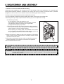
6. DISASSEMBLY AND ASSEMBLY
- Cautions to be observed when trouble shooting.
Unlike many other appliances, the microwave oven is high-voltage, high-current equipment. It is completely safe
during normal operation. However, carelessness in servicing the oven can result in an electric shock or possible
danger from a short circuit. You are asked to observe the following precautions carefully.
1. Always remove the power plug from the outlet before servicing.
2. Use an insulated screwdriver and wear rubber gloves when servicing the high voltage side.
3. Discharge the high voltage capacitor before touching any oven components or wiring.
(1) Check the grounding.
Do not operate on a two-wire extension cord.
The microwave oven is designed to be used while grounded.
It is imperative, therefore, to make sure it is grounded
properly before beginning repair work.
(2) Warning about the electric charge in the high voltage capacitor.
For about 30 seconds after the operation has stopped, electric
charge remains in the high voltage capacitor.
When replacing or checking parts, short between oven chassis
and the negative high terminal of the high voltage capacitor by
using a properly insulated screwdriver to discharge.
4. When the 15A fuse is blown out due to the operation of the monitor
switch; replace primary interlock switch, secondary interlock switch
and interlock monitor switch.
5. After repair or replacement of parts, make sure that the screws are
properly tightened, and all electrical connections are tightened.
6. Do not operate without cabinet.
CAUTION : Service personnel should remove their watches whenever working close to or replacing the magnetron.
WARNING : When servicing the appliance, take care when touching or replacing high potential parts because of
electrical shock or exposing microwave. These parts are as follows - HV Transformer, Magnetron,
HV Capacitor, HV Diode.

8
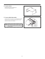
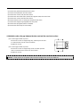
1. To remove cabinet
1) Remove four screws on cabinet back.
2) Push the cabinet backward.
2. To remove guide wind assembly
1) Remove two screws which secure the stopper hinge top.
2) Remove the door assembly from top plate of cavity.
3) Reverse the above for assemby.
NOTE: After replacting the door assembly, perform a
check of correct alignment with the hinge and
cavity front plate.

9
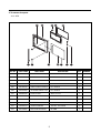
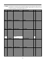
REF NO. PART CODE PART NAME DESCRIPTION Q’TY REMARK
A01 3512603550 HANDLE DOOR ABS SG-0760D, SG-175 1
A02 3515307410 SUPPORTER HANDLE ABS SG-0760D, SG-175 2
A03 3512204760 FRAME DOOR ABS XR-401, SR-0320 1
A04 7122401211 SCREW TAPPING T2S TRS 4X12 MFZN 2
A05 3517001100
BARRIER SCREEN *O SEALING AS
KOC-1B5K9S 1
A06 3515204900 STOPPER HINGE *T AS KOC-1B4K0S 1
A07 3516602100 DOOR-PLATE SBHG-1A T0.7 1
A08 3513101200 HOOK POM 1
A09 3515101800 SPRING HOOK PW1 1
A10 3512302300 GASKET DOOR PRT 1
A11 7122401211 SCREW TAPPING T2S TRS 4X12 MFZN 2
A12 3511618600 DECORATOR BADGE NI 70MM 1
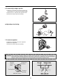
3. To remove door parts.
- KOC-1B5K

10
(1) Remove the gasket door(A10) from door plate.
(2) Remove door plate(A07) from door frame.
(3) Remove two screws (A11) from door frame.
(4) Remove the door handle (A01) and handle supporter (A02) from door frame.
(5) Remove two screws (A04) from door frame.
(6) Remove barrier screen *O sealing AS (A05) from door frame.
(7) Remove the stopper hinge top(A06) from door plate.
(8) Remove the spring(A09) and the hook(A08).
(9) Reverse the above steps for reassembly.
4. Method to reduce the gap between the door seal and the oven front surface.
(1) To reduce gap located on part ‘A’.
• Loosen two screws on stopper hinge top, and then push the door
to contact the door seal to oven front surface.
• Tighten two screws.
(2) To reduce gap located on part ‘B’.
• Loosen two screws on stopper hinge under, and then push the
door to contact the door seal to oven front surface.
• Tighten two screws.
NOTE : A small gap may be acceptable if the microwave leakage does not exceed 4mW/cm
2
.

11
(1) Remove five screws (B10) and eight screws (B08) which secure the control panel.
(2) Pull out the Main PCB assembly(B09).
(3) Pull out the Knob volume(B05) from the Main PCB assembly.
(4) Pull out the decorator ring (B06) from knob volumes.
(5) Pull out two buttons from the control panel.
(6) Pull out the LED HOLDER (B07) from the main PCB assembly.
(7) Pull out Window display (B01) from the control panel.
(8) Reverse the above steps for reassembly.
-KOC-1B5K
REF NO. PART CODE PART NAME DESCRIPTION Q’TY REMARK
B01 3515501820 WINDOW DISPLAY PMMA 1
B02 3516724160 C-PANEL ABS SG-0760D, SG-175 1
B03 3516908390 BUTTON FUNCTION-A ABS SG-175 SG-0760D 1
B04 3516908490 BUTTON FUNCTION-B ABS SG-175 SG-0760D 1
B05 3513406090 KNOB VOLUME ABS SG-175 SG-0760D 2
B06 3511605170 DECORATOR RING ABS SG-175, SG-0760D COATING 2
B07 3513004800 LED HOLDER PP 1
B08 7121301011 SCREW TAPPING T2S PAN 3X10 MFZN 8
B09 PKMPMSAD50 MAIN PCB ASS’Y KOC-1B5K9S 1
B10 7122401211 SCREW TAPPING T2S TRS 4X12 MFZN 5
5 To remove control panel parts.

12
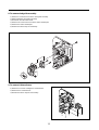
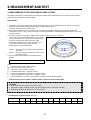
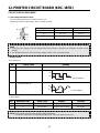
CAUTION : Never install the magnetron without the metallic gasket plate which is packed with each magnetron to
prevent microwave leakage. Whenever repair work is carried out on magnetron, check the microwave
leakage. It shall not exceed 4mW/cm
2
for a fully assembled oven with door normally closed.
Magnetron
antenna
<MAGNETRON>
Metallic
gasket
plate
Cooling fin Filament
terminal
6. To remove high voltage capacitor.
1) Remove a screw which secure the grounding ring
terminal of the H.V. diode and the capacitor holder.
2) Remove the H.V. diode from the capacitor holder.
3) Reverse the above steps for reassembly.
◆ High voltage circuit wiring
7. To remove magnetron.
1) Remove a screw which secure the magnetron.
2) Remove the magnetron.
3) Reverse the above steps for reassembly.

13
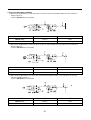
8. To remove wind guide assembly.
1) Remove a screw which secure the wind guide assembly.
2) Draw forward the wind guide assembly
3) Pull the fan from the motor shaft.
4) Remove two screws which secure the motor shaded pole.
5) Remove the motor shaded pole.
6) Reverse the above steps for reasembly.
9. To remove H.V.transformer.
1) Remove four screws holding the H.V.transformer.
2) Remove the H.V.transformer.
3) Reverse the above steps for reassembly.

14
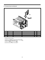
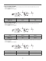
10. To remove Top heater assembly parts.
1) Remove a screw which secure the wind guide assembly.
2) Pull out Guide air outlet .
3) Remove two screws which secure Insulator heater *t.
4) Pull out Insulator heater *t .
5) Pull out Harness heater .
6) Pull out Bracket heater *t from Cover heater *t.
7) Remove Heater miraclon from Cover Heater *t.
REF NO. PART CODE PART NAME DESCRIPTION Q’TY REMARK
17S312X40A1 SCREW TAPPING T1 TRS 4*10 MFZN 1
23512520500 GUIDE AIR OUTLET SA1D-80 T0.5 1
33513302800 INSULATOR HEATER *T SECC T0.5 1
47S312X40A1 SCREW TAPPING T1 TRS 4*10 MFZN 2
53512767000 HARNESS HEATER KOC-1B0K0S 1
63510607700 BRACKET HEATER *T SA1D-80 T0.5 1
73512803820 HEATER MIRACLON 60V 550W 1
83511407600 COVER HEATER *T STS430 T0.5 1

15
11. To remove Lamp assembly parts.
1) Pull out the Lamp assembly.
2) Remove a screw which secures Holer Lamp Assembly.
3) Pull out Lamp and Holder lamp as from Cover lamp .
4) Detach Lamp from Holder lamp as .
5) Pull out Cover lamp from Cover lamp .
6) Reverse the above steps for reassembly.
REF NO. PART CODE PART NAME DESCRIPTION Q’TY REMARK
13511407800 COVER LAMP STS430 T0.5 1
23513602600 LAMP HALOGEN 120V 20W 1
33513003910 HOLDER LAMP AS KOC-1B0K5A 1
47112401011 SCREW TAPPING T1 TRS 4*10 MFZN 1
53511407810 COVER LAMP T/GLASS T2.0 1

16
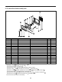
12. To remove Rear heater assembly parts.
1) Remove a screw and pull out Cover motor *B .
2) Remove a screw and pull out Cover *B .
3) Pull out the Harness convection-B .
4) Remove four screws and then pull out the Rear heater assembly.
5) Remove a Nut and the pull out the Fan convection and Washer plain .
6) Remove a screw and then separate the Cover heater *B and the lnsulator heater *B .
7) Pull out two Heater miraclon from the Cover Heater *B .
8) Remove two screw and then separate the lnsulator heater *B and Motor shaded pole .
9) Remove the C-Ring and then pull out the Fan from Motor shaft.
10) Reverse the above steps for reassembly.
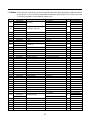
REF NO. PART CODE PART NAME DESCRIPTION Q’TY REMARK
17S312X40A1 SCREW TAPPING T1 TRS 4*10 MFZN 2
23511407300 COVER MOTOR *B SA1D-80 T0.5 1
37S312X40A1 SCREW TAPPING T1 TRS 4*10 MFZN 2
43511407400 COVER *B SA1D-80 T0.5 1
53512766900 HARNESS CONVEC *B KOC-1B0K0S 1
63512803820 HEATER MIRACLON 60V 550W 2
73511407700 COVER HEATER *B SA1D-80 T0.5 1
87113400814 SCREW TAPPING T1 BIN 4X8 MFNI 1
97400104011 WASHER PLAIN PW-1-4 MFZN 1
10 3511800700 FAN CONVECTION SA1D-80 T0.5 1
11 7S627W40X1 SPECIAL SCREW NUT FLANGE M4 MFZN 1
12 3512766800 HARNESS CONVEC *A KOC-1B0K0S 1
13 7601400811 SCREW MACHINE PAN 4X8 PW MFZN 2
14 3513302900 INSULATOR HEATER *B SBHG-1 T0.5 1
15 7113400814 SCREW TAPPING T1 BIN 4X8 MFNI 4
16 3963822630 MOTOR SHADED POLE 120V 60HZ MW10XA 1
17 3511800900 FAN PBT 1
18 7402704600 RING C CR-5 SK5 1

17
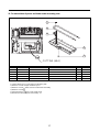
13. To remove Motor Synchro and Under heater assembly parts.
1) Cut the Motor syncro cover parts from the base plate.
2) Remove a screw and pull out Motor syncro.
3) Remove a screw which secures Under heater assembly.
4) Remove a screw .
5) Pull out Heater *U from Cover heater *u .
6) Reverse the above steps for reassembly.
CUTTING (6EA)
1
2
3
4
5
REF NO. PART CODE PART NAME DESCRIPTION Q’TY REMARK
17S312X40A1 SCREW TAPPING T1 TRS 4*10 MFZN 1
23511407500 COVER HEATER *U STS430 T0.5 1
33515304000 SUPPORTER HEATER *U STS430 T0.5 1
43512805100 HEATER *U 120V 400W 1SOPE4543002 1
57113400814 SCREW TAPPING T1 BIN 4X8 MFNI 1

18
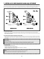
7. INTERLOCK MECHANISM AND ADJUSTMENT
The door lock mechanism is a device which has been specially designed to completely eliminate microwave radiation when
the door is opened during operation, and thus to perfectly prevent the danger resulting from the leakage of microwave.
(1) Primary interlock switch
When the door is closed, the hook locks the oven door. If the door is not closed properly, the oven will not operate.
When the door is closed, the hook pushes the button of the microswitch. Then the button of the primary interlock switch
bring it under ON condition.
(2) Secondary interlock switch and interlock monitor switch
When the door is closed, the hook pushes the lock lever downward. The lock lever presses the button of the interlock
monitor switch to bring it under OFF condition and presses the button of the secondary interlock switch to bring it under
ON condition.
(3) Adjustment steps
a) Loosen the one mounting screw.
b) Adjust interlock switch assembly position.
c) Make sure that lock lever moves smoothly after adjustment is completed.
d) Tighten completely two mounting screws.
ADJUSTMENT :
Interlock monitor switch
When the door is closed, the interlock monitor switch should be opened before other switches are closed.
When the door is opened, the interlock monitor switch should be closed after other switches are opened.
NOTE :
Microwave emission test should be performed after adjusting interlock mechanism.
If the microwave emission exceed 4mW/cm
2
, readjust interlock mechanism.

19
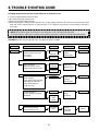
8. TROUBLE SHOOTING GUIDE
Following the procedure below to check if the oven is defective or not.
1) Check grounding before trouble checking.
2) Be careful of the high voltage circuit.
3) Discharge the high voltage capacitor.
4) When checking the continuity of the switches, fuse or high voltage tranformer, disconnect one load wire from these
parts and check continuity with the AC plug removed. To do otherwise may result in a false reading or damage to
your meter.
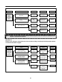
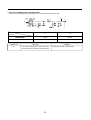
(TROUBLE 1) Oven does not operate at all : any inputs can not be accepted.
NOTE :
When electric parts are checked, be sure the power cord is not inserted the wall outlet.
Check wire harness, wiring and connection of the terminals and power cord before check the parts listed below.
CONDITION CHECK
Check continuity of
interlock monitor switch with
door closed
( COM↔NC )
Check continuity of
both primary and secondary
interlock switch with door closed
Malfunction of
Interlock
monitor switch
Malfunction of
interlock switch
RESULT
Continuity
No continuity
CAUSE REMEDY
Replace
(COM↔NC)
Fuse blows.
Replace
Shorted contacts
of primary
interlock Switch
Continuity Replace
Check continuity of
primary interlock switch contact with
door partially open until interlock
monitor switch contact close
( COM↔NC close )
Defective low
voltage
transformer
Defective
high voltage
transformer
0 Ωor infinite Replace
Replace
Check continuity of
primary winding of low voltage
transformer
Disconnect high voltage
fuse and operate the unit
No
Continuity
Continuity
Approx.
530Ω
( normal )
Fuse again
blows
Page is loading ...
Page is loading ...
Page is loading ...
Page is loading ...
Page is loading ...
Page is loading ...
Page is loading ...
Page is loading ...
Page is loading ...
Page is loading ...
Page is loading ...
Page is loading ...
Page is loading ...
Page is loading ...
Page is loading ...
Page is loading ...
Page is loading ...
Page is loading ...
Page is loading ...
Page is loading ...
Page is loading ...
Page is loading ...
-
 1
1
-
 2
2
-
 3
3
-
 4
4
-
 5
5
-
 6
6
-
 7
7
-
 8
8
-
 9
9
-
 10
10
-
 11
11
-
 12
12
-
 13
13
-
 14
14
-
 15
15
-
 16
16
-
 17
17
-
 18
18
-
 19
19
-
 20
20
-
 21
21
-
 22
22
-
 23
23
-
 24
24
-
 25
25
-
 26
26
-
 27
27
-
 28
28
-
 29
29
-
 30
30
-
 31
31
-
 32
32
-
 33
33
-
 34
34
-
 35
35
-
 36
36
-
 37
37
-
 38
38
-
 39
39
-
 40
40
-
 41
41
-
 42
42


Ask a question and I''ll find the answer in the document
Finding information in a document is now easier with AI
Related papers
-
 DAEWOO ELECTRONICS KOC-1B0K0S User manual
-
Daewoo KOC-910K0S01 User manual
-
Daewoo KOR-6NFB User manual
-
Daewoo KOC-9Q4T7S User manual
-
Daewoo KOC-621Q User manual
-
-
-
-
Daewoo KOC-9Q3T7S User manual
-

Other documents
-
 DAEWOO ELECTRONICS KOR-637V0A User manual
-
GE TMW-1100EC User manual
-
 DAEWOO ELECTRONICS KOR-61850N User manual
-
Magic Chef MCD1311ST Owner's manual
-
Gasmate EH240 User manual
-
-
 TRUSTECH KPT-1606F User manual
-
HANYOUNG NUX TH510 Owner's manual
-
Samsung SMH7175WE Operating instructions
-


