Page is loading ...

© 2003 SPX Corporation Sheet No.
Issue Date: Rev. C, February 14, 2005
Form No. 520825
Parts List &
Operating Instructions
for: 1545
1 6 Pin Shaft
2 2 Front Wheel
4 11 Washer
5 10 Back Ring
6 2 Rear Wheel
7 2 Spring Washer
8 2 Nut
(M12)
9 2 Spring
10 2 Leveling Screw
11 1 Pump Assembly
12 5 Spring Washer
13 2 Bolt
(M8 x 18)
14 1 Pump Pedal Assembly
1
1
1
2
2
4554
1
1
6
4554
6
7
8
9
10 14
12
20 15
16
34
454
5
4
5
45
32
32
32
30
33
31
32
30
29
28
29
30
24
23
25 25
35
26
27 10
11 1
12
13 13
12
4
18
17
19
1220
2022
12
21
15 1 Pin Shaft
16 1 R-pin
17 1 Positioning Button
18 2 Screw
(M6 x 10)
19 1 Pulling Frame
20 3 Bolt
(M8 x 12)
21 1 Pushing Rod
22 1 Pin
(4 x 25)
23 1 Lock Bar
24 1 Lifting Arm Assembly
25 2 Pin Shaft
26 2 Bushing
27 2 Washer
Item
No. Qty. Description Item
No. Qty. Description Item
No. Qty. Description
28 2 R-pin
29 2 Supporting Rod
30 4 Bushing
(Short)
31 2 Bushing
(Long)
32 4 Pin Shaft
33 1 Bracket Assembly
34 1 Handle
35 1 Spring
PARTS INCLUDED BUT NOT SHOWN
2 Hold Down Strap
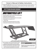
Parts List
1 of 3
Motorcycle/ATV Lift
Max. Capacity: 1,500 lbs.
SPX Corporation
655 Eisenhower Drive
Owatonna, MN 55060-0995 USA
Phone: (507) 455-7000
Tech. Serv.: (800) 533-6127
Fax: (800) 955-8329
Order Entry: (800) 533-6127
Fax: (800) 283-8665
International Sales: (507) 455-7223
Fax: (507) 455-7063
Shaded areas reflect the last
revisions made to this form.

Item
No. Qty. Description
No. 522447 Handle includes:
34 1 Handle
No. 522448 Caster Kit includes:
6 1 Rear Wheel
7 1 Spring Washer
8 1 Nut
(M12)
No. 522449 Wheel Kit includes:
1 1 Pin Shaft
2 1 Front Wheel
4 1 Washer
5 1 Back Ring
No. 522450 Foot Pedal Kit includes:
12 1 Spring Washer
14 1 Pedal Assembly
20 1 Bolt
(M8 x 12)
No. 531043 Hold Down Strap Kit includes:
2 Hold Down Strap
No. 522451 Power Unit Kit includes:
4 1 Washer
11 1 Pump Assembly
12 2 Spring Washer
13 2 Bolt
(M8 x 18)
15 1 Pin Shaft
16 1 R-pin
No. 522452 Lock Bar Kit includes:
17 1 Positioning Button
18 2 Screw
(M6 x 10)
23 1 Lock Bar
No. 522453 Return Spring:
35 1 Spring
No. 522454 Leveling Screw Kit includes:
9 1 Spring
10 1 Leveling Screw
Replacement Kits for the Motorcycle/ATV Lift Assembly
No. 522455 Platform Kit includes:
4 4 Washer
5 4 Back Ring
30 4 Bushing
(Short)
31 2 Bushing
(Long)
32 4 Pin Shaft
33 1 Bracket Assembly
No. 522456 Load Yoke Kit includes:
19 1 Pulling Frame
25 2 Pin Shaft
26 2 Bushing
27 2 Washer
28 2 R-pin
No. 522457 Riser Arms Kit includes:
1 4 Pin Shaft
4 8 Washer
5 8 Back Ring
24 1 Lifting Arm Assembly
29 2 Supporting Rod
30 4 Bushing
(Short)
31 2 Bushing
(Long)
32 4 Pin Shaft
No. 522501 Handle Mount Kit includes:
12 2 Spring Washer
20 2 Bolt
(M8 x 12)
21 1 Pushing Rod
22 1 Pin
(4 x 25)
Item
No. Qty. Description
Parts List & Operating Instructions Form No. 520825, Sheet 1 of 3, Back

© 2003 SPX Corporation Sheet No.
Issue Date: Rev. C, February 14, 2005
2
3
4
5
6
7
8
9
10
11
12
13
14
15
1617
18 19
20
21
22
23
24
25
26
27
28
19
29
19
30
37
38
39
31
32
33
25
34 36
35
21
40
2 1 Washer
3 1 Cylinder
4 1 O-ring
5 1 Bowl Washer
6 1 Piston Ring
7 1 Piston Shank
8 1 Top Nut
9 1 O-ring
10 1 Seal Ring
11 1 Iron Block
12 1 Oil Plug
13 1 Reservoir
14 1 Seal Ring
15 1 Screw
16 1 Seal Washer
17 1 Spring
18 1 Ball Valve Base
19 3 Steel Ball
(6.0)
20 1 Pin Shaft
(8 x 45)
21 4 R-pin
22 1 Release Valve
23 1 O-ring
24 1 Screw
25 2 O-ring
26 1 Spring
27 1 Ball Valve Base
28 1 Steel Ball
(4.0)
Item
No. Qty. Description Item
No. Qty. Description Item
No. Qty. Description
29 1 Filter Screen
30 1 Washer
31 1 Pump Body
32 1 Umbrella Ring
33 1 Back Ring
34 1 Piston
35 1 Handle Sleeve
36 1 Link
37 1 Release Pedal
38 1 Spring
39 1 Spring Base
40 3 Pin Shaft
(8 x 28)
Parts List & Operating Instructions Form No. 520825
Parts List
Pump Assembly
2 of 3

Item
No. Qty. Description
No. 521612 Seal Kit includes:
2 1 Washer
4 1 O-ring
5 1 Bowl Washer
6 1 Piston Ring
9 1 O-ring
10 1 Seal Ring
12 1 Oil Plug
14 1 Seal Ring
16 1 Seal Washer
19 2 Steel Ball
(6.0)
23 1 O-ring
25 2 O-ring
29 1 Filter Screen
30 1 Washer
32 1 Umbrella Ring
33 1 Back Ring
No. 521613 Release Pedal Kit
includes:
20 1 Pin Shaft
(8 x 45)
21 1 R-pin
37 1 Pedal
No. 521614 Handle Socket Kit
includes:
21 3 R-pin
35 1 Handle Sleeve
36 1 Link
40 3 Pin Shaft
(8 x 28)
No. 521615 Pump Station Kit
includes:
19 1 Steel Ball
(6.0)
21 1 R-pin
25 1 O-ring
30 1 Washer
31 1 Pump Body
32 1 Umbrella Ring
33 1 Back Ring
34 1 Piston
38 1 Spring
39 1 Spring Base
40 1 Pin Shaft
(8 x 28)
Replacement Kits for the Pump Assembly
No. 521616 Reservoir Kit includes:
8 1 Top Nut
9 1 O-ring
10 1 Seal Ring
11 1 Iron Block
13 1 Reservoir
14 1 Seal Ring
29 1 Filter Screen
No. 521617 Ram Kit includes:
2 1 Washer
3 1 Cylinder
4 1 O-ring
5 1 Bowl Washer
6 1 Piston Ring
7 1 Piston Shank
9 1 O-ring
10 1 Seal Ring
14 1 Seal Ring
19 1 Steel Ball
(6.0)
29 1 Filter Screen
No. 521618 Hardware Kit includes:
15 1 Screw
16 1 Seal Washer
17 1 Spring
18 1 Ball Valve Base
19 1 Steel Ball
(6.0)
22 1 Release Valve
23 1 O-ring
24 1 Screw
25 1 O-ring
26 1 Spring
27 1 Ball Valve Base
28 1 Steel Ball
(4.0)
Item
No. Qty. Description
Parts List & Operating Instructions Form No. 520825, Sheet 2 of 3, Back

© 2003 SPX Corporation Sheet No.
Issue Date: Rev. C, February 14, 2005
Safety Precautions
CAUTION: Failure to follow these warnings could cause damage and / or failure of equipment,
which may result in personal injury or property damage. To prevent personal injury and damage to
equipment,
•Study and understand all safety precautions and operating instructions before using this cylinder.
If the operator cannot read these instructions, operating instructions and safety precautions must
be read and discussed in the operator’s native language.
•Wear protective eyewear that meets the requirements of ANSI Z87.1 and OSHA.
•Inspect the jack before each use; do not use the jack if it’s damaged, altered, or in poor condition.
•Use the jack for lifting purposes only.
•A load must never exceed the rated lifting capacity of the jack. Secure the load with tie down loops.
•Only use the jack on a hard, level surface.
•Stay clear of lifted loads, and the pinch points of the jack.
•Do not modify the jack or use adapters unless approved or supplied by OTC.
•Lower the jack slowly and carefully while watching the position of the jack saddle.
•Use only approved hydraulic fluid (Mobile DTE #13 or equivalent). The use of alcohol, hydraulic brake
fluid, or transmission oil could damage seals and result in jack failure.
This guide cannot cover every situation, so always do the job with safety first.
Parts List & Operating Instructions Form No. 520825
Bleeding Air From The Jack
1. Depress and hold down the release pedal while operating the pump pedal 5–10 times.
2. Release air from the bottle jack by carefully lifting a corner of the fill plug on the side of the bottle jack.
Operating Instructions
To raise the jack, operate the pump pedal.
To lower the jack, SLOWLY depress the release pedal.
3 of 3

Preventive Maintenance
IMPORTANT: The greatest single cause of failure in hydraulic units is dirt. Keep the motorcycle/ATV jack
clean and well lubricated to prevent foreign matter from entering the system. If the jack has been exposed to
rain, snow, sand, or grit, it must be cleaned before it is used.
1. Store the jack in a well-protected area where it will not be exposed to corrosive vapors, abrasive dust, or any other
harmful elements.
2. To check the oil level, completely retract the ram. Remove the plug from the oil filler hole. The oil level should be within
1/4" of the filler plug hole. If necessary, add approved anti-wear hydraulic jack oil (Mobile DTE #13 or equivalent), and
install the filler plug again. IMPORTANT: The use of alcohol, hydraulic brake fluid, detergent motor oil, or
transmission oil could damage the seals and result in jack failure.
4. Inspect the jack before each use. Take corrective action if any of the following problems are found:
a. Cracked or damaged housing d. Scored or damaged piston rod
b. Excessive wear, bending, or other damage e. Loose hardware
c. Leaking hydraulic fluid f. Modified or altered equipment
Troubleshooting Guide
Repair procedures must be performed in a dirt-free environment by qualified personnel who are familiar with this equipment.
Trouble Cause Solution
Erratic action 1. Air in system
1. Refer to section titled “Bleeding Air from the
Jack.”
2. Oil viscosity too high
2. Change to a lower viscosity oil.
3. Internal leakage in cylinder
3. Replace worn packings. Look for
excessive contamination or wear.
4. Cylinder sticking or binding
4.
Look for dirt, gummy deposits, leaks,
misalignment, worn parts, defective packings.
Jack does not lift 1. Release valve is open
1. Close release valve.
2. Low/no oil in reservoir
2. Fill with oil and bleed system.
3. Air-locked system
3. Bleed system.
4. Load is above capacity of jack
4. Use correct equipment.
5. Delivery valve and/or bypass
5. Clean to remove dirt or foreign matter.
valve not working correctly
Replace oil.
6. Packing worn out or defective
6. Repair power unit.
Jack lifts only partially 1. Too much or not enough oil
1. Check oil level.
Jack advances slowly 1. Pump not working correctly
1. Repair power unit.
2. Leaking seals
2. Repair power unit or seals.
Jack lifts load, but doesn’t hold 1. Cylinder packing is leaking
1. Repair power unit or seals.
2. Valve not working correctly (suction,
2. Inspect valves. Clean and repair seat
delivery, release, or bypass)
surfaces.
3. Air-locked system
3. Bleed system.
Jack leaks oil 1. Worn or damaged seals
1. Repair power unit or seals.
Jack will not retract 1. Release valve is closed
1. Open or clean release valve.
2. Locking bar engaged
2. Raise jack slightly, disengage locking bar.
Jack retracts slowly 1. Cylinder damaged internally
1. Send jack to OTC authorized service center
for repair.
2. Link section is binding
2. Lubricate link section.
Parts List & Operating Instructions Form No. 520825, Sheet 3 of 3, Back
/