
REV:02/14/13

Zonar Systems’ V3R™ Hardware Installation Tips
For Professional Installers
Zonar Systems’ equipment will provide years of reliable service if properly installed and maintained.
Zonar equipment is typically installed in heavy vehicle applications and is often subject to extreme
temperatures, dust, dirt, vibration, and shock. Proper installation is the critical first step to equipment
longevity and optimal performance.
This guide is meant to be a general guideline for the professional installer and technician. While we
attempt to point out the most common installation questions and issues; common sense, good
housekeeping procedures, attention to detail, safety adherence, and technical competence of the
professional installer is critical for a successful installation.
Please refer to your specific vehicle manufacturer guidelines for the installation of electrical components
and wiring.
A professional team of Zonar support technicians and engineers are available to answer your installation
questions. Contact Zonar at 1-877-843-3847 or by email at customercar[email protected].
Thank you,
Andre J Horochiwsky
Technical Training Manager – Zonar Systems
As Zonar Systems is continuously improving the Product, Zonar may make changes to the Product at any time which may not be reflected in this document.
INTRODUCTION
2

V3R™
Introduction ................................................................................................2
System Overview........................................................................................4
V3R Equipment .........................................................................................5
General Guidelines .....................................................................................6
V3R Mounting ............................................................................................7
V3R Cable Management.............................................................................8
Power Cable Wiring Guidelines...................................................................9
External GPS Antenna Installation.............................................................10
System Check..........................................................................................11
System Checklist......................................................................................12
System Components and Specifications ..................................................13
Installation Examples ................................................................................14
System Installation Diagram......................................................................15
Troubleshooting...................................................................................16-17
Warranty & Notices - FCC Compliance.....................................................18
TABLE OF CONTENTS
3
© 2013 Zonar Systems • EVIR, ZPass,Ground Traffic Control and V3R are trademarks of Zonar
Systems. All Rights Reserved.
Products and services protected by one or more of the following US patents: 6671646, 6804626,
7117121, 7362229, 7557696, 7564375 and Australian patent: 2002322510
REV: 02/14/13

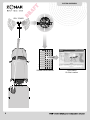
SYSTEM OVERVIEW
4
CUSTOMER
On-Site Location
ZONAR Secure Servers
CELL TOWER
INTERNET

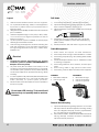
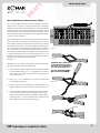
V3R EQUIPMENT
5
Fuse Holders
ATC Style
Fuses
Crimpable
Butt Splices
V3R POWER CABLE
ZONAR V3R™
INSTALLATION HARDWARE
Mounting
Hardware

Layout
1) V3R unit must be located a minimum of 8” from any person.
2) Do not place Zonar RFID tags, cables, or other equipment in
any location or position which may compromise human or
equipment safety.
3) Verify placement acceptability with State DOT/Law enforcement
prior to installation.
4) V3R has a temperature range of -40˚C (-40˚F) to +85˚C (+185˚F).
Do not mount V3 in hot engine compartments or near hot
exhaust components.
5) Lay all components out prior to installation to check for proper
cable length and interference issues.
6) Avoid mounting Zonar equipment, antennas and wiring near
other radio equipment (e.g.,two-way radios), PA equipment
and high energy electrical sources (e.g., cables, relays,
amplifiers, etc.).
Electrical
1) Consult the vehicles manufacturer for specific
installation guidelines. (HIGHLY RECOMMENDED for
Multiplex electrical systems)
2) All power leads (Red and White Power leads) must be
connected to the vehicles protected circuitry (e.g. fuse panel,
circuit breaker panel, protected circuits). Never electrically
connect Zonar equipment to unprotected circuits (e.g. directly
to battery).
3) It is also required that all power leads (Red and White Power
leads) be protected with a 3 to 5 amp fuse and inline fuse
holder (included) for optimal system protection.
4) Electrical fuses should be installed as close as possible to
the source of power.
Do not open V3R housing. To do so will void
the warranty and possibly lead to moisture
intrusion.
Drill Holes
1) Do not drill into the V3R unit. This will void the warranty.
2) Capture all drill chips during drilling operations. Do not allow
chips to fall onto equipment, furnishings, etc.
3) Deburr all drill holes on both sides of drilled surface. Example
deburr tool:
4) All drill holes must have a rubber grommet or similar anti-
chaffing system installed to protect cable assemblies (e.g.
plastic conduit).
5) Seal all penetration drill holes which may pass rain water.
Cable Management
1) Strain relieve and support all cable installations.
2) Avoid sharp bends and tight radius installations of cables.
3) Avoid moving components (e.g. doors, steering shafts, handles,
fans, etc.).
4) Provide an adequate “Service Loop” i.e. “cable slack” to allow
for servicing of equipment.
5) Avoid routing cables thru doors, windows, and other pinch
points.
6) Avoid routing cables in high personnel traffic areas.
7) Avoid routing antenna cables near radio and PA equipment.
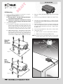
GENERAL GUIDELINES
6
INCORRECT
• Bend radius too tight
• Hole has sharp edges
• Hole has no grommet
CORRECT
• Bend radius adequate
• Hole has grommet
General Housekeeping
1) Capture all drill chips during drilling operations. Do not allow
drill chips to fall onto electrical equipment, furnishings, heating
ducts, etc. Magnets, sticky tape, vacuums, physical barriers,
etc. may all be used to accomplish this task.
2) Remove excess sealant. Sealant should be debris/contaminant
free (e.g. drill chips), consistent, and uniform in appearance.
Clip excess wire tie protrusions.

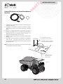
V3R Mounting
1)
Follow all General Guidelines as specified on page 6.
2) Suggested mounting areas:
See page 14.
A) Box type trailers - Left side rooftop (preferred) or
front vertical surface (alternate)
B) Construction equipment - Protected from moving
equipment, impact damage and high heat areas
3) Antenna Configurations:
A) GPS antenna - V3R utilizes an internal GPS antenna. This
antenna works well when the unit has a clear view of the
sky (e.g. atop box trailer. If the V3R does not have a
clear/unobstructed view of the sky (e.g. engine
compartment) an external GPS antenna must be used.
B) GSM (cellular antenna) - V3R utilizes an internal GPS
antenna. Cellular signals are quite robust and are not
easily degraded. As a general rule, if your cellular telephone
works in the location you have installed the V3R, this
should satisfy the GSM/Cellular requirements of the V3R.
Fig. 7-1
4) Mount onto interior flat surface large enough to accommodate
footprint.
5) Avoid mounting equipment in difficult to access areas.
6) If enclosing in a radio-shielded area (e.g., metallic enclosure)
an external GPS antenna will be necessary for proper operation
and performance.
7) Avoid mounting Zonar Equipment, antennas and wiring near
other radio equipment (e.g.,two-way radios), PA equipment
and high energy electrical sources (e.g., cables, relays,
amplifiers, etc.).
8) Avoid mounting equipment in dirty, dusty, or damp areas.
9) Please take note of:
• GPS ID number – Found on white sticker on GPS unit
• Vehicle or Asset number (e.g. Bulldozer #56)
Note: Your Zonar Customer Care Representative or Ground Traffic
Control Administrator will need this information.
V3R MOUNTING
Fig. 7-2
Bolt
Mount
(Provided)
Magnetic
Mount
(Provided)
7
Mount V3R Facing
Skyward
7

1) Follow all General Guidelines as specified on page 6.
2) It is strongly recommended to keep Zonar electrical connections
outside "master kill" circuitry. Failing to do so may lead to
inaccurate data (See caution notice this page).
3) Connecting V3R to negative/ground side "master kill" circuits
(commonly found on construction equipment) may lead to false
idle times.
4) All power leads must be connected to the vehicle’s protected
circuitry (e.g. fuse panel, circuit breaker panel, protected circuits).
Never electrically connect Zonar equipment to unprotected
circuits (e.g. directly to battery).
5) It is also required that all power leads (Red and White leads),
be protected with a 3 to 5 amp fuse and inline fuse holder
(included) for optimal system protection.
6) Electrical fuses should be installed as close as possible to the
source of power.
7) Power Bundle wiring – 4 Pin, 3 wires
A. Red – Constant DC (+8 VDC - +30 VDC), dependent
on system type
B. Black – Ground must be less than 1 ohm (measure from
4 Pin connector to chassis attachment point)
C. White - Switched Power
The White wire must be connected to a power source that
is active only when the engine is running or the system
will not track idle time properly
i. Engine running (+8 VDC to +30 VDC)
ii. Engine NOT running (0 VDC)
iii. Engine NOT running (key position ACC or Accessory)
Mode (0 VDC)
Electrical Requirements and Cabling Information
V3R CABLE MANAGEMENT
8
21’ Power Cable
If power cabling is not connected and powered as
described in paragraph 7, one or more of the following
may occur, contact Zonar for additional info:
A. Cold Start flags (an indicator that a unit lost and regained
constant power)
B. Inaccurate idle and stop times
C. Inaccurate hour meter data
D. Inaccurate mileage data
E. Missing path data
F. Straight line data segments
Please contact the vehicle manufacturer for any vehicle
specific electrical questions.

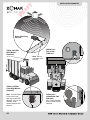
Wiring Guidelines for Zonar Power Cables
The recommended method for power termination on the Zonar
V3R system is the use of Add-a-Circuit fuse taps. Whenever
possible, use fuse taps for power termination. If, due to the particular
make/model/year of the vehicle being installed, fuse taps cannot
be used then the poke and weave method of termination can be
utilized. All wiring terminations MUST be fused regardless of Add-
a-Circuit or poke and weave.
When installing Add-a-Circuit fuse taps, ensure that the fuse tap
seats fully in the correct location. If another fuse, a relay, or any
other object in the fuse panel prevents the fuse tap from seating
fully, relocate the fuse tap. It is not permissible for the fuse tap to
rub or make contact with other items in the fuse panel. In addition,
you must be able to re-secure the fuse panel cover or door once
the fuse tap is installed. Whenever possible, use an empty location
in the fuse panel that does not have an existing fuse. If it is not
possible to use an empty location, ensure that the existing fuse is
placed in the correct location on the fuse tap.
See Fig. 9-1
Whenever it is not possible to utilize Add-a-Circuit fuse taps then
the poke and weave method should be used.
1) First locate the proper wire where the poke and weave method
is to be installed. Strip 3/4” to 1” of insulation from the wire in
the vehicle to be installed. Spread the wire strands apart as
shown. See Fig. 9-2
2) Strip 1” to 1 1/2” of insulation from the wire in the fused link
to be installed. See Fig. 9-3
3) Insert the wire from the fused link into the spread wire in the
vehicle. Wrap around the wire several times. See Fig. 9-4
4) Cover the exposed wires with several wraps of electrical tape
or mastic. Place one wire tie over the electric tape over the
exact location where the wires are 'wrapped' together. Place
another wire tie 1” to 2” from the first wire tie, to secure the two
wires together and as stress relief. See Fig. 9-5
Fig. 9-1
Wire Tie
Fig. 9-5
Fig. 9-4
Fig. 9-3
Fig. 9-2
WIRING GUIDELINES
9
CAUTION: Only “LittleFuse”
(www.littlefuse.com) Add-A-
Circuit taps are authorized for
use with Zonar Equipment.
Full size: (ATO) P/N FHA200
Mini version: P/N FHM200

External GPS Antenna and Double Sided Adhesive
(Optional)
1) Required when the V3R does not have an upward facing clear
view of the open sky.
2) Suggested mounting area - as high on the vehicle as possible,
facing upward. Protect from moving machinery and falling
debris.
3)
Follow all General Guidelines as specified on page 6.
4) May be magnetically mounted or mounted via optional aluminum
plate and screw for non-magnetic surfaces, see Fig. 10-1.
5) Ensure a clear antenna view of the open sky.
6) Maintain a minimum of 6 inches from any rooftop edge or ledge,
see Fig. 10-1.
7) Drill, deburr, grommet, weather seal, cable thru hole as required.
Drill hole size - 1/2” (.500”); grommet size - 3/8” (.375”).
8) Protect exposed GPS cable with automotive grade impact and
cut resistant loom.
Note: For optimal system performance Zonar recommends rooftop
mounting with a clear view of the sky.
Fig. 10-2
ANTENNA INSTALLATION
10
• Allow a minimum of
6 inches from any
edge or ledge
• Drill hole size: 1/2” (.500”)
• Grommet size: 3/8” (.375”) I.D.
• Drill, Deburr, grommet, weather
seal, cable thru hole as required
1” - 2”
recommended
Fig. 10-1

System Check:
1) Installers are required to perform a full functional check to
verify proper installation and operation. A complete functional
check includes Ground Traffic Control™ confirmation.
2) Constant (RED wire) power check
A. Remove inline fuse on constant power (Red wire) and
measure voltage at red fuse holder.
3) Switched power (White wire) power check
A. Power to this lead should only be present when the
engine is on and/or GPS tracking is desired. Wiring this
to constant power will lead to high and inaccurate idle
times.
B. Remove inline fuse on switched power (White wire) and
measure voltage at fuse holder:
Engine running = 8 to 30 VDC
Engine Off = 0 Volts
4) Final check
A. Turn engine on for 4 minutes or more, then turn off engine.
B. In Zonar’s Ground Traffic Control™ export path CSV (GPS,
path report), ensure exported CSV contains:
1. Cold Start
2. Power-On event
3. Power-Off event
4. Idle Event (idles must be over 1 minute)
Note: A proper and complete functional check requires the engine
to be running.
Contact Zonar at 1-877-843-3847 or by email at
customercar[email protected] if you encounter any
issues or difficulties.
SYSTEM CHECK
11

INSTALLER SIGNATURE Date
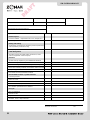
V3R SYSTEM CHECKLIST
12
Customer: Yard: Date: Asset #:
Installer: Location: GPS ID:
Vehicle Odometer Value: Vehicle I.D. (e.g., Vin, Plate#, Make, Model, Year)
Vehicle Hour Meter value (if monitoring engine hours)
System Check Value Notes
General Layout
General condition - components level, even, straight, etc?
System layout conforms to your established standard?
Drilling and Cutting
All drill holes grommeted (or otherwise protected), deburred,
sealed (weather penetrations only)
All chips captured?
Cable Management
All cables properly ran (tight radius, interference, strain
relieved, supported, service looped)?
Electrical
System hookup complies to your established standard?
Red lead voltage verified? (8 -30V constant)
White lead voltage verified? (8 -30V engine on, 0V engine off)
Black lead continuity verified? (Grounded to vehicle chassis)
Crimp integrity verified?
Fuse holder and fuse installation verified?
Ground Traffic Control™ System checkout
Cold start present?
Power-on check
Power-off check
Idle time check? (Requires an idle of over 1 minute)
GPS Position uploaded to GTC website?
Post Job
Key accounted for?
Vehicle secure?
Lights, electrical off?
All debris, refuse, chips removed?

Important Notice
It is the Owner's sole responsibility to install and use the Zonar
products in a manner that will not cause accidents, personal injury
or property damage. For the purposes of this notice, "Owner",
"you" and "your" means the party (including any person authorized
by that party to use and/or install the Product) that has either: (a)
purchased the Product; or (b) leased the Product from Zonar
Systems, Inc or its related companies. The Owner of this product
is solely responsible for observing safe driving practices. The
choice, location, and installation of all components of the Product
is critical. If installation is not correct, the Product may not perform
at its designed potential or specifications. If in doubt, consult your
vehicle's manufacturer.
SYSTEM SPECIFICATIONS
13
System Components & Specifications
COMPONENTS
• V3R™ GPS Unit
• 3 wire power harness magnetic and bolt-thru mounting kits
Optional Accessories:
• External GPS Antenna
SPECIFICATIONS
• Operating Temp: -40˚C (-40˚F) to +85˚C (+185F)
• DC Input Range: 8.0Vdc to 30.0Vdc
GPS Receiver
• Very High Sensitivity Receiver
• Rapid Acquisition of Satellites
• GPS Signal Acquisition, Tracking and Navigation
• Onboard GPS Data Storage
DIMENSIONS
• Length: 9.485 in.
• Width: 8.313 in.
• Height: 2.534 in.
COMMUNICATION
GSM Cellular Transceiver
• Quad Band 850/1900 900/1800
• GPRS

Mount V3R Facing
Skyward
INSTALLATION EXAMPLES
14
Trailer, Left Side
Roof Mount -
Preferred
Trailer Left Side
Front High Mount-
Alternate
Yellow Iron -
Top of Cab
Preferred
Yellow Iron -
Inside Back Cab
Alternate
Min. 8” from Operator -
External GPS Antenna
Required
Note: The V3R needs
a clear view to the
open sky to track GPS
satellites. If this is not
possible, install
optional external GPS
antenna.
Note: Secure
wire/cable every
6 inches.

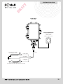
External GPS Antenna
(Optional Accessory)
Part#: 10006
Cable Length: 16.5 ft.
Switched
Power (White)
GND (Black)
Constant Power Supply
Input Voltage: 8-30VDC
Engine Running: 8-30 VDC
Acc/Accessory mode, Engine Not Running: 0 VDC
+12VDC (Red)
3A-5A
SYSTEM INSTALLATION
15
3A-5A
Zonar V3R™
Part#: 10083
20 AWG

16
TROUBLESHOOTING
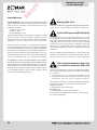
Common V3R™ issues
The majority of all V3R issues fall into six broad categories:
•GPS Signal Strength Issues. The V3R must be given a clear
view to the open sky to operate correctly. If this cannot be
accomplished an external GPS antenna with a clear view to the
sky must be utilized.
• Cellular Signal Strength Issues. The V3R cannot transmit
in areas that are not covered by cellular towers (typically remote
areas). The V3R will store information until cellular reception is
restored and then forward all stored data.
• Cold Starts: These are the most serious issue because they
represent a lack of integrity in the constant power supply to the
device. Before any other issue can be resolved, it is important
to ensure that the V3R has reliable constant power.
• Issues with the Engine Run Signal: These lead to false
reporting of engine hours. The problem can be false positive
(e.g. V3R records engine hours even if the asset is not running)
as well as false negative (e.g. V3R does not record engine hours
even though the asset is running)
• V3R™ Issues: Inside every V3R is a Zonar V3R™ GPS unit.
Therefore, typical V3R issues can arise with any V3R. Since
much of the V3R troubleshooting information references LEDs
which are hidden inside the waterproof V3R enclosure, in most
cases you will need to contact Zonar Customer Support for
help.
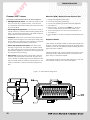
White Wire (WW) / Switched Power Electrical Test
1. Engage the equipment master switch.
2. Connect Zonar harness to V3R case
3. Connect the negative meter probe to the Zonar GND wire.
4. Turn engine off.
5. Refer to Figure 1-16 and locate the WW pin on the 35-pin
connector. Probe this pin with the positive meter probe.
6. To pass the inspection, the meter must show less than 1V.
7. Turn engine on.
8. Probe the WW pin. To pass, the meter should read greater than
5V.
Inspection Results
If both steps 6 and 8 result in PASS, the V3R passes the electrical
inspection. However, if the equipment is acting up only under certain
conditions (i.e. hot day, rainy weather) the test should be performed
again under those conditions.
If either test results in FAIL, perform the WW continuity tests. Once
the wiring has been verified, repeat this test. If the result is FAIL
again, swap in a new V3R and repeat.
If the inspection does not pass even after swapping in a new V3R,
note the failure condition, and contact Zonar support.
Figure 1-16 V3R Cable Pin Assignments

17
TROUBLESHOOTING
Power and Ground Electrical Tests
Unexplained cold starts are the most serious issue because they
represent a lack of integrity in the constant power supply to the
device. Before any other issue can be resolved, it is important to
ensure that the V3R has reliable constant power. Simply following
this procedure may not be enough. However, if the equipment is
acting up only under certain conditions (i.e. hot day, rainy weather)
the test should be performed again (and again?) under these
conditions.
1. Engage the equipment master switch
2. Connect Zonar harness to V3R™ case
3. Prepare multi-meter to measure volts.
4. Connect the negative meter probe to Zonar GND wire.
5. Refer to Figure 1-16 and locate the V+ pin on the 35-pin
connector. Probe this pin with the positive meter probe.
6. To pass the inspection, the voltage must be at or near battery
voltage. If not, perform the Power and Ground Wiring
Inspection. Then repeat this test.
7. If the test passes, power cycle the V3R, and confirm that a Cold
Start event occurred on GTC. Otherwise, note the failure
condition, and contact Zonar Support.
Test Result
If the Electrical test passes, but the V3R continues to show
unexplained cold starts, note the conditions under which the cold
starts occur. Repeat the Power and Ground Wiring Inspection
procedure and the above procedure under those conditions. If
possible, mount the meter in the operator’s cab and run the test
continuously for several hours.

18
WARRANTY & NOTICES
FCC/IC COMPLIANCE
Limited Warranty
LIMITED WARRANTY: Zonar warrants that the Hardware provided
under this agreement is free from all material defects in workmanship
under normal use and service. Zonar’s warranty period for its
Hardware is as follows:
V3 Product Line - 5 Years
EVIRTM - 3 Years
All Other Hardware - 1 Year
The above warranty periods run from the date of shipment. Provided
that the Hardware is used and handled as intended, Zonar will
replace any failed or functionally impaired Hardware with equivalent
Hardware in terms of performance and functionality.
This warranty does not apply to any Hardware that has been
misused, altered, willfully abused or that has been damaged due
to improper installation by the customer.† Hardware installations
must follow Zonar’s equipment specific installation guidelines.† If
product returned is determined to be damaged due to any of the
aforementioned circumstances, the Customer will be charged the
price of a refurbished unit plus shipping and handling.
CUSTOMER’S SOLE AND EXCLUSIVE REMEDY AND ZONAR’S
ENTIRE OBLIGATION UNDER THESE LIMITED WARRANTIES for
defective equipment is the repair and replacement of the equipment
free of charge by Zonar. Zonar shall not be liable to Customer or
any third party for any general, special, punitive, incidental, indirect
or consequential damages, or any lost profits or business, arising
out of Zonar’s Subscription Agreement.
Warning: (Part 15.21)
Changes or modifications not expressly approved by Zonar Systems
could void the user's authority to operate the equipment.
Caution: RF Exposure (OET Bulletin 65)
To comply with FCC RF exposure requirements for mobile
transmitting devices, the antenna(s) used for this transmitter must
be installed to provide a separation distance of at least 20cm (8
Inches) from all persons and must not be co-located or operating
in conjunction with any other antenna or transmitter. Users and
installers must be provided with antenna installation instructions
and transmitter operating conditions for satisfying RF exposure
compliance.
Use only supplied and approved antenna's. Use of unauthorized
antenna's or modifications could impair signal quality, void your
warranty and/or result in violation of FCC regulations.
FCC Compliance Statement (Part 15.19)
IC Compliance Statement (RSS-210)
This device complies with Part 15 of the FCC Rules and with RSS-
210 of Industry Canada (IC). Operation is subject to the following
two conditions:
1. This device may not cause harmful interference, and
2. This device must accept any interference received, including
interference that may cause undesired operation.
Cet appareil est conforme aux normes CNR exemptes de licence
díIndustrie Canada. Le fonctionnement est soumis aux deux
conditions suivantes :
(1) cet appareil ne doit pas provoquer
díinterfèrences et
(2) cet appareil doit accepter toute interfèrence,
y compris celles susceptibles de provoquer un fonctionnement
non souhaitè de líappareil.

NOTES
19

© 2013 Zonar Systems • All Rights Reserved.
REV:02/14/13
V3R™ USERS MANUAL
& INSTALLATION GUIDE
-
 1
1
-
 2
2
-
 3
3
-
 4
4
-
 5
5
-
 6
6
-
 7
7
-
 8
8
-
 9
9
-
 10
10
-
 11
11
-
 12
12
-
 13
13
-
 14
14
-
 15
15
-
 16
16
-
 17
17
-
 18
18
-
 19
19
-
 20
20


Zonar V3R User manual
- Type
- User manual
- This manual is also suitable for
Ask a question and I''ll find the answer in the document
Finding information in a document is now easier with AI
Other documents
-
 VHC Brands 21609 User guide
-
 National Fleet Tracking NFT-4550 Installation guide
-
Midmark IQecg® Owner's manual
-
-
Hygain V-3R User manual
-
Dell Vizioncore User guide
-
Philips Medical Systems North America PQC-MX40SRR User manual
-
-
-
 Dunham-Bush WCFX 27 Installation, Operation & Maintenance Manual


