Page is loading ...

LAVINA® 25-S-E User Manual
www.superabrasive.com / factory@superabrasive.com

Superabrasive UserManual OriginalLanguageLavina®25‐S‐E 8/2014
2
1.GENERALINFORMATION
Preface3
Manufacturer 3
GeneralDescription 3
MachineCharacteristics 3
MainDesign 3
EnvironmentalConditions 3
ElectricalConnection 3
VacuumConnection 4
TechnicalData 4
Vibrations4
SonorousEmissions 4
LabelData4
CustomerService 4
2.SAFETYINSTRUCTIONS
RecommendedUse 4
ProhibitedUse 4
PreparationforWork 5
ProtectionDevices 5
ArrestFunctions 5
SafeUse5
ResidualRisks 5
BeforeYouBegin 5
OperatingMachine 5
AfterWorkisCompleted 5
TheWorkArea 5
PersonalProtectiveEquipment(Ppe) 5
Operator5
3.HANDLINGANDTRANSPORTATION
PreparingtheMachineforTransportation 6
LifttheMachinefromWorkingtoToolMounting
Position6
Lifting6
AdjustingtheHandle 6
Storage6
4.OPERATION
PreliminaryControls 7
WaterFlowControlUnit 7
AdjustingandMountingTools 7
FrameBlocking(U‐Joint) 7
ControlBoard 8
StartingtheMachine 8
OperatingtheMachine 8
StoppingMachine 8
Alarm8
5.TOOLSANDACCESSORIES
Weights9
ToolHolderKey 9
FoamPlate9
SecurityPlateforQuickchangePads 9
6.POPULARTOOLS 10
7.EXPLODEDVIEW
GeneralExplodedView(Fig.7.1) 11
TopCoverExplodedView1(Fig.7.2) 11
PlanetaryDriveExplodedView(Fig.7.3) 11
TopCoverExplodedView2(Fig.7.4) 11
BottomCoverExplodedView1(Fig.7.5) 12
BottomCoverExplodedView2(Fig.7.6) 12
PulleyUnitsExplodedView(Fig.7.7) 12
CarriageExplodedView(Fig.7.8) 12
ToolHolderExplodedView(Fig.7.9) 12
8.MAINTENANCEANDINSPECTION
Cleaning13
CheckDaily 13
Checkandreplaceafterthefirst15WorkingHours 13
CheckEvery200WorkingHours 13
CheckEvery400WorkingHours 13
Vacuum13
WaterLeaks 13
MechanicalParts 13
ElectricalSystem 13
ElectricalSchemes380Volt 14
9.TROUBLESHOOTING
IndexofProblemsandSolutions
9.1ReplacingPowerCordandPlugs 15
9.2DismountingandMountingToolHoldertochangebuffers
andspiders,changingV‐RingsandFelt‐Rings15
9.3TensioningandReplacethePlanetaryBelt 16
9.4TensioningUsedPlanetaryBelt 16
9.5MountingandTensioninganewPlanetaryBelt 16
9.6CheckingtheTensionoftheBelt 17
9.7ReplacingofthePulleyUnits 18
9.8MountingtheBelt 19
9.9MotorConnection 19
9.9FaultDiagnosisInverterYASKAWAV1000 20
10.WARRANTYANDRETURNS
Warranty23
ReturnPolicy 23
11.DISPOSAL
Disposal23
12.MANUFACTURER’SCONTACTS
Manufacturer’scontract 23
13.SPAREPARTS
13.1GeneralParts/formachinesproducedbeforeJan.12014/24
13.1GeneralParts/formachinesproducedafterJan.12014/24
13.2TopCoverParts1/formachinesproducedbeforeJan.12014/25
13.2TopCoverParts1/formachinesproducedafterJan.12014/25
13.3TopCoverParts2 26
13.4PlanetaryDriveParts 26
13.5GuardParts 26
13.6BottomCoverParts1 27
13.7BottomCoverParts2 27
13.8PulleyUnitsParts 28
13.8a.Pulley Unit Assembly 28
13.8b.Driving Pulley Unit 28
13.9WaterSupplyParts/formachinesproducedbefore
Jan.12014/ 28
13.9WaterTankParts/formachinesproducedafter
Jan.12014/ 28
13.10ToolHolderParts 29
13.11CarriageParts/formachinesproducedbeforeJan.12014/29
13.11CarriageParts/formachinesproducedafterJan.12014/30
13.13ControlBoxParts380Volt 31

Superabrasive UserManual OriginalLanguageLavina®25‐S‐E 8/2014
3
1.GENERALINFORMATION
Thisowner’smanualisintendedfortheoperatoroftheLavina®S‐Emachine,theservicingtechnicianaswellasforanyone
involvedwithoperatingorservicingthemachine.Werecommendthatyoureadtheinstructionsverycarefullyandfollowthem
strictly.Themanualincludesinformationaboutassembling,using,handling,adjustingandmaintainingyourLavina®S‐Efloor
grindingandpolishingmachine.
MANUFACTURER
Superabrasivewasfoundedin1987,asamanufacturerofhighqualitydiamondtoolsforthestoneandconcreteindustry.Today,
Superabrasiveisoneoftheworld’sleadingcompaniesintheproductionofdiamondtoolsandfloorgrindingmachinery.At
Superabrasive,westrivetodelivertheverybestsolutionstoourcustomers,andenablethemtoworkmoreefficiently.
GENERALDESCRIPTION
TheLavina®S‐Emachineisintendedforgrinding,polishingandbuffingconcrete,marble,granite,limestone,andterrazzosurfaces
withdiamondtools.
TheLavina®S‐Emachineisathree‐discmachine,whichcanbeuseddryaswellaswet.
Forbestresults,useonlytoolsmanufacturedorrecommendedbySuperabrasiveanditsdistributors.Additionally,themachine
couldbeusedforgrindingwoodfloorsurfaces.
TheLavina®S‐Emachineismanufacturedandfittedfortheabove‐mentionedapplicationsonly!Every
otherusemaypossessriskstothepersonsinvolved.
MACHINECHARACTERISTICS
TheLavina®S‐Emachineismadeoftwomaincomponentsections:
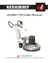
MAINDESIGN
Thetwomaincomponentsections,arethecarriageandmainhead.
Thehandle(Fig.1.2)ontheframeisadjustableinheightandallowstheoperatortoworkin
acorrectandsafeworkingposture.
Thehalogenspotlight(Fig.1.2)enablestheoperatortoworkindarker
areas.
Existinglightingsystemdoesnotreplaceadequateoverheadlighting.
Aframe(U‐jointtechnology)ontopofthemotorbaseallowsthemainheadtomovetoall
sidesanditgivesmoregrindingcapacity.
Thecontrolsarepositionedontopoftheelectricalbox(fig.1.3)
Theelectricalbox(fig.1.3)containstheelectricswitchingdevicesandtheinverter.
Themainfeedingcableisconnectedwithaplugandsocketontop.Themotorfeeding
cableispluggedintothesocketlocatedonthebottomofthebox.
Thetankisontheoppositesideoftheframe,sothattheweightofthe
waterhasnoinfluenceontheoperationofthemachine.Theframeweight,ontheother
hand,isfullyabsorbedbythedrivingwheels.Anelectricpumpspraysthewaterthrougha
frontsprayerorinternal.
Themotorismountedonthebaseplateandisdrivingthethreeheadswithabeltsystem.
Theplanetaryheadisdrivenbyasecondflatbelt.
ENVIRONMENTALCONDITIONS
ThetemperaturerangeforoperatingtheLavina®S‐Emachineoutdoorsisbetween41°Fand
86°For5°Cand30°C.NeverusetheLavina®S‐Emachineduringrainorsnowwhenworking
outdoors.Whenworkingindoors,alwaysoperatethemachineinwell‐ventilatedareas.
ELECTRICALCONNECTION
Thevoltage(Volt)andpower(Ampere)aredisplayedonalabelontheelectricalcontrolbox
toavoidanyincorrectconnection.Refertothesebeforeconnectingthepower.Toavoid
electricalshocks,makesurethegroundpowersupplyisfunctioningproperly.Figure 1.3
Figure 1.1
Figure 1.2

Superabrasive UserManual OriginalLanguageLavina®25‐S‐E 8/2014
4
VACUUMCONNECTION
Aconnectionforavacuumdustextractorislocatedonthecarriage.TheLavina®S‐Emachinedoesnotincludeavacuumdust
extractor.Thecustomermustpurchasethevacuumdustextractorseparately.ThehoseofthevacuumextractormustbeØ50
mmandcanbeglidedoverthepipe.Thevacuumdustextractormustbeadaptedforfloorgrindersandhaveaminimumair
displacementof320m3/hwithanegativevacuumof21kPa.
TECHNICALDATA
CE‐CERTIFICATION
TheLavina®S‐Emachineisdesignedtooperatecorrectlyin
anelectromagneticatmosphereofindustrialtypeandis
equippedwithallthemechanicalandelectricalsafety
protectionsinconformitywiththefollowingEuropeanCEE
rulesandregulations:
TheLavina®S‐EmachinecomplieswiththeSafetyDirective
formachines2006/42/EC,theEMCDirective2004/108/EC
andtheLowVoltageDirective2006/95/EC.
AlsocomplieswiththenormsinuseBDSENISO12100,BDS
EN13862,BDSENISO13857,BDSEN349,BDSENISO
13850,BDSEN13732‐1,BDSEN953,BDSENISO13849‐
1,BDSEN1037,BDSENISO5349‐1,BDSENISO11201,BDS
ENISO3744,BDSEN1033:2002,BDSEN60204‐1,BDSEN
1837,BDSEN61000‐6‐4,BDSEN61000‐6‐2,BDSEN61000‐
4‐2,BDSEN61000‐4‐4,BDSEN61000‐4‐5,BDSEN61000‐4‐
11,BDSEN55016‐2‐1
Testresultsareapartofthemachine’stechnical
informationandcanbesentuponaspecialrequest.ThemachineisdeliveredwiththeCEmarkexposedandprovidedwithaEC
declarationofconformity.
VIBRATIONS
Themeasuredvibrationvalueonthesurfaceofgrippingincaseofguidingthemachineisahw=2,17m/s2.Themeasurementis
madeinaccordancewiththeBDSENISO1033andBDSENISO5349‐1.
SONOROUSEMISSIONS
Themaximumnoiselevelatdistanceofthemachineof1mincaseofworkingatidledoesnotexceed70dB(A).Themeasurementismadein
accordancewiththeBDSENISO11201andBDSENISO3744.
LABELDATA
ThedataonthelabelprovidesthecorrectVoltageandkW(neededforoperationalpurposes);
Weight(neededfortransportationpurposes);productionyearandserialnumber(neededformaintenancepurposes
CUSTOMERSERVICE
ForcustomerassistanceandtechnicalsupportcallyourlocaldistributororcallSuperabrasiveLtd.orvisitusat:
www.superabrasive.com,whereyoucandownloadacopyofthismanual.
2.SAFETYINSTRUCTIONS
RECOMMENDEDUSE
TheLavina®S‐Emachineisdesignedandmanufacturedtogrind
andpolishconcrete,terrazzo,andnaturalstonefloors.Itcanbe
usedforrenovationaswellasforpolishing.Themachineis
designedfordryorwetuse.Whenusingitdry,useavacuumof
appropriatesize.Formoreinformation,pleaserefertothe
chapteronhandlingthevacuumconnection.
PROHIBITEDUSE
ThemachineMUSTNOTbeused:
Forapplicationsdifferentfromtheonesstatedinthegeneral
descriptionchapter.
Fornon‐suitablematerials.Inenvironmentswhich:
- Possessrisksofexplosion,
- Possesshighconcentrationofpowdersoroilsubstancesin
theair,
- PossessrisksoffireFeatureinclementconditions,
- Possesselectromagneticradiation.
PREPARATIONFORWORK
Makesurethat:
Youhaveclosedtheworkarea,sothatnopersonunfamiliar
withoperatingthemachinecanenterthearea.
Thetoolplateandtoolsareadjustedtothemachine
properly.
Therearenomissingpartsofthemachine
Lavina®25‐S‐E
Voltage/Hz3phx380V50‐60Hz
AmperageMax15Amps
Power7,5kW10HP
Toolholderrpm300‐1100rpm
Workingwidth655mm25”
Tooldiameter(QCPlate)3x225mm3x9”
Weight251kg553lbs
Grindingpressure130kg287lbs
Additionalweightmax2x29kgmax2x64lbs
Applicationwetanddry
VacuumhoseportYes
Watertankcapacity20l5.2gal
Waterfeedwithpump(peripheralandfront)
Cablelength17.4m57ft
MachineLxWxH1880x690x1180mm74x27.2x46.5”
PackingLxWxHonskid1150x730x1530mm45.3x28.7x60.2”
PackingLxWxHCrate11150x730x1100mm45.3x28.7x43.3”
+Crate21150x730x900mm45.5x28.7x35.4”

Superabrasive UserManual OriginalLanguageLavina®25‐S‐E 8/2014
5
Themachineisinuprightworkingposition.
Theprotectiondevicesareworkingproperly.
Theelectricalcableisfreetomoveandfollowthemachine
easily.
Inordertokeeptheelectricalcablefrombeingdamaged,no
vehicleshouldcrossthezonewhereelectricalcablesare
situated.
PROTECTIONDEVICES
Themachineisequippedwithseveralprotectiondevices
includingthefollowing:
Anemergencystopbutton
Aprotectionskirtandahoodforprotectingthetoolplates.
Thesedevicesprotecttheoperatorand/orotherspersons
frompotentialinjuries.Donotremovethem.Beforeusingthe
machine,pleaseensurethatallprotectiondevicesare
mountedandfunctionproperly.TheSecurityplateprevents
theQuickChangepadstofromlooseningduringwork
ARRESTFUNCTIONS
Functionsofarrestingofthemachinearefollowing:
Buttontostopthemotor(category1)
Emergencybutton(category1)
SAFEUSE
TheLavina®S‐Eisdesignedtoeliminateallriskscorrelatedwith
itsuse.However,itisnotpossibletoeliminatetherisksofan
eventualaccidentwiththemachine.Unskilledoruninstructed
operatormaycausecorrelatedresidualrisks.Suchrisksare:
PositionRisks:duetooperator’sincorrectworkingposition
TanglingupRisks:duetowearinginappropriateworking
clothes
TrainingRisks:duetolackofoperationaltraining.
NOTE::Inordertoreduceallconsequencesoftheabove‐
mentionedrisks,weadvisethatmachineoperatorswill
followtheinstructionsinthemanualatalltimes.
RESIDUALRISKS
Duringthenormaloperatingandmaintenancecycles,the
operatorisexposedtofewresidualrisks,whichcannotbe
eliminatedduetothenatureoftheoperations.
BEFOREYOUBEGIN
Workingareamustbeclearfromanydebrisorobjects.
Afirst‐timeoperatormustalwaysreadthemanualandpay
attentiontoallsafetyinstructions.
Allelectricconnectionsandcablesmustbeinspectedfor
potentialdamages.
Groundwiresystemofthepowersupplymustbealso
inspected.
Performgeneraldailyinspectionsofthemachineand
inspectthemachinebeforeeachuse.
Alwaysinspectthesafetydevices:MounttheSecurityplate
fortheQuickChangepads.
Theemergencybreakmustbeclearandworking
Thetoolprotectormustbeworking
Themachinemustbeclean
Neveroperatethemachineintherain!
Confirmthattherearenomissingpartsespecially
aftertransportation,repairormaintenance.
Beforefillingthewatertankwithwatermakesure
themachineisnotworkingandthemainswitchis
turnedoff.
Beforeturningonthemachinemakesurethatthebaseis
placedonthefloor,themachineMUSTNOTbeinanupright
positionwhenturnedon!
OPERATINGMACHINE
WhenoperatingtheLavina®S‐E,makecertainthatthereis
noone,butyouaroundthemachine.
Neverleavethemachineunattendedwhileworking.
Theelectricalcablemustmovefreelyandmustbe
damage‐free.
Thewaterhosemustmovefreelyandmustbedamage‐free.
Checktomakesurethefloor,youarepreparingtoworkon,
iseven.Ifthefloorisuneven,itmaydamagethemachine.
AfterWorkiscompleted
Cleanthemachineanditssurroundingsproperly
Emptyandcleanthewatertank
Unplugthemachineandwinduptheelectricalcable
Storethemachineinasafeplace
THEWORKAREA
Makecertainthatpeopleorvehiclesdonotenterthework
area.
Avoidcablesandhosesbeingintheway.
Alwayscheckthefloorfordebris
PERSONALPROTECTIVE
EQUIPMENT(PPE)
Alwayswearsafetyshoeswhenworkingwiththe
machine.
Alwayswearearprotectorswhenworkingwiththe
machine.
Allpersonnelintheimmediateworkareamustwear
safetyglasseswithsideshields.
Alwayswearsafetygloveswhenchangingthetools.
Alwayswearclothessuitablefortheworkenvironment.
OPERATOR
TheLavina®S‐Emachine.
Theoperatormustknowthemachine’swork
environment.Onlyoneoperatoratatimecanworkwith
themachine.Theoperatormustbeproperlytrainedand
wellinstructedprioroperatingthemachine.
Theoperatormustunderstandalltheinstructionsinthis
manual.
Theoperatormustunderstandandinterpretallthedrawings
anddesignsinmanual.
Theoperatormustknowallsanitationandsafetyregulations
pertainingtotheoperationof
Theoperatormusthavefloorgrindingexperience.
Theoperatormustknowwhattodoincaseofemergency.
Theoperatormusthaveanadequatetechnicalknowledge
andpreparation.

Superabrasive UserManual OriginalLanguageLavina®25‐S‐E 8/2014
6
3.HANDLINGANDTRANSPORTATION
PREPARINGTHEMACHINEFORTRANSPORTATION
Unplugthemotorcableplugfromthecontrolboxanddisconnectthewaterhosefromthemainheadbypullingitout
(Fig.3.1)(Fig.3.2).Windtheelectricalcableonthecarriage.Releasethepinsetswhichattachtheheadtothecarriage.Pull
outthevacuumhoses(Fig.3.3),anddismounttheheadfromthecarriage.
TheheadoftheLAVINA®S‐Emachinehasonebarforsupportandisusedashandlesforeasymovingandtransportation.
LIFTTHEMACHINEFROMWORKINGTOTOOL
MOUNTINGPOSITION
Pushthefronthandledownandswivelittothe
front(Fig.3.4).Pullthehandleupandensurethe
headisastableuprightposition,for
mounting/dismountingthetool.Ensurethatthe
watertankisemptybeforeflippingthemachine.
Pulltheheadinuprightposition(Fig.3.5).The
machinesmanufacturedafterJan.12014are
withchangedlockingofthefronthandleas
shownonthefig.3.4.1
LIFTING
Liftingthemachinebycraneispossiblewiththeeyebolt,whichismountedonthecarriage(seeFig.
3.6).Theeyeboltandmachineconstructionisratedonlyfortheweightofthemachine.Donotlist
anyotherleadsonthemachine.Alwaysusehoistingequipmentratedfor300kgor660lbs.
ADJUSTING THE
HANDLE
TheHandleontheframe
isadjustableinheight
andallowstheoperator
toworkinacorrectand
safeposture.The
machinesmanufactured
afterJan.12014are
withchangedlockingof
thehandleonthe
frame.Theunlockingisbypullingthehandle(fig.3.7.1)Thelockingisautomaticallyunderactionofthespring.Fig.3.7.2shows
allpossiblepositionofthehandle.Choosetheuprightpositiontomoveeasythemachine.
Figure 3.1 Figure 3.2 Figure 3.3
Figure 3.6
Figure 3.5
Figure 3.4 Figure 3.4.1
Figure 3.7 Figure 3.7.1 Figure 3.7.2 Figure 3.8

Superabrasive UserManual OriginalLanguageLavina®25‐S‐E 8/2014
7
STORAGE
AlwaysstoreandtransporttheLavina®S‐E
machineinadryplace.Nevertransportthe
Lavina®S‐Emachineunprotected;itmaybe
damagediftransportedunprotectedduring
rainorsnow.
Whenstoringthemachinethetemperaturemayfalldowntoortolessthan32F(or0oC)youshouldemptythewaterfromthe
systemusingthefollowingsteps:
‐Pulloutthehoseofthetank(Fig.3.9)
‐Usingcompressedairblowoutthewaterfromthesystemforthetwopositionsoftheturn‐cock(Fig.3.10,Fig.3.11).
4.OPERATION
PRELIMINARYCONTROLS
Inspecttheworkingareaasexplainedinthesafetyinstructions.Forwetuse,fillthewatertankwhentheelectricalcableis
disconnected.Connectthevacuumextractorandensurethatthevacuumhoseisclearandthatitwilleasilyfollowthemachine.
PluginthemachineandmakesurethatthepowercordisfreetofollowthedirectionoftheworkingLavina®S‐Emachine.
WATERFLOWCONTROLUNIT
Theoperatorcanchoosethewatersprayerinthefrontwhenthetapisinthehorizontalposition(Fig.4.1),thewater
willsprayunderthecoverofthemachine
whenthelevelisintheverticalposition
(Fig.4.2).Theflowregulatingvalvelocatedon
thetank(Fig.4.2.1)isincreasingorreducing
thewaterflowtothe
working
area–infront
ofthemachineorunderthemainheadcover
ofthe
machine
/onlyformachinesproduced
afterJan.12014/
.
ADJUSTINGANDMOUNTINGTOOLS
Mountthetoolsonlyafterensuringthatthereisenough
diamondbondmaterialleft.Besurethattheplatesarealways
cleanbeforemounting.WARNING:Alwayssecurethe
“QuickChange”padswiththesecurityplate(Fig.4.3),lockwith
thetoolholderkey(Fig.5.3).DiamondtoolswithVelcroare
attachedtothree9inchfoamplates(Fig.4.4).Thefoamplates
aremountedonthekeylock(butterfly).Alwaysusethetool
holderkey(Fig.5.3).
FRAMEBLOCKING(U‐JOINT]
Therelationbetweentheworkingheadandthetrolleyistheframe(U‐joint),whichallowsthe
rotationoftwoperpendicularaxestobetterfollowthefloors’profile.
Themovementalongtheoneaxiscanbesecuredwithtwoscrews(fig.4.5)andthatblocksthelateral
movementofthemachine.
Figure 4.4
Figure 4.3
Fgure 4.5
Figure 3.9 Figure 3.10 Figure 3.11
Figure 4.2.1
Figure 4.1 Figure 4.2

Superabrasive UserManual OriginalLanguageLavina®25‐S‐E 8/2014
8
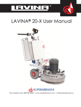
THECONTROLBOARD
1. Powercableplug
2. DigitalRPMindicatorIndicatestherevolutionperminuteofthegrindingplates(nottherevolutionperminuteoftheentire
unit).
3. Polishing/GrindingswitchIn“grinding”position,theoperatorhasthepossibilitytocontroltherpmfrom300until
maximum700rpm.In“Polishing”positionfrom300‐1100rpmmaximum.
4. Lampcablegland
5. InverteralarmledLightsbluewhentheinvertergoesintoalarmmode.
6. WaterpumpswitchLightsorangewhenthewaterpumpisworking.
7. Powerledlightsgreenwhenthepowerison
8. Forward/Reverseswitchchooseforwardforclockwiserotation
ofthegrindingplatesorreverseforanti‐clockwiserotationofthe
grindingplates
9. PotentiometerchangestheRPMofthegrindingplatesfrom
300‐1100rpm
10. Resetbuttonresetsthealarmoftheinverter
11. OFFbuttonstopsthemotor
12. ONbuttonstartsthemotor
13. EmergencybuttonusedinEmergencysituationsforstoppingthe
motor
STARTINGTHEMACHINE
First,followthedirectionsinchapterSafetyDevicesandSafety
Instructions.Next,pulltheemergencystop(13)toensurethatthe
machineisinworkingcondition.Checkthepotentiometer(9)and
ensurethatitissetatworkingspeed.Ifworkingwet,addwatertothe
floor’ssurface.Ifworkingdry,omitthisstep,andinstead,switchon
thevacuumunit.Finally,holdthemachinefirmlyandpushthestart
button(12).
OPERATINGTHEMACHINE
Guidethemachineinstraightlinesacrossthefloor,andwitheachnewlineoverlapalittlebitofthepreviouslycompletedsurface.
Workataconstantspeed,allowingthetoolstimetoworkataspeedappropriateforthetools’gritsize.Avoidvibrations.Donotstop
theLavina®S‐Eononespotwhilethetoolsarestillworkingbecausetheywillleavemarksonthefloors’surface.Whenworkingwet,
firstchoosethewatertap(Fig.4.2)andthepositionforthewaterfeed,periodicallystarttopumpandreleasewaterontothefloor’s
surface(Fig.4.6Pos.6).Whenworkingdry,checkthefloor’ssurfaceperiodicallytoensurethatdustisnotaccumulatingonthe
surface,alsocheckregularlytomakesureyourvacuumisworkingproperly.
STOPPINGTHEMACHINE
TheThestoppingofthemachinemustbedonegraduallyuntilthemotorstops.Donotstopmovingthemachinebeforearrestingthe
motorasthetoolscoulddamagethesurface.Tostop,pushthe“Off”button(11).Usetheemergencybutton(13)onlyinemergency
oruseittoswitchthepowertotallyoff.Remembernottoholdthemachineinonespotbeforeturningoffthemotor.
ALARM
Thealarmlight(5)willlightincaseinvertergoesintoalarmmode.Themostcommonfailureismotorinoverload.Toresetthemode,
pushthe“reset”button(10).
12345678
910111213
Fgure 4.6

Superabrasive UserManual OriginalLanguageLavina®25‐S‐E 8/2014
9
5.TOOLSANDACCESSORIES
WEIGHTS
Superabrasiveoffersadditionalweightsforincreasingtheproductivityofthemachine(Fig.5.1).
Eachadditionalweightweighsabout64lbsor29kg.Eachindividualapplication,typeandcondition
ofsurface,powercapacityoftheoutlet,etc.willdeterminethenumberofweightsyoucanuse
withouttrippingabreaker.Theweightstacksontothreepoststhatarearoundtheouterbowl
(Fig.5.2).Theadditionalweightsdependonthetools;itisnotalwayspossibletoassweights.Some
toolsworktooaggressivelyandthemachinecanstop.Theweightcanbeorderedwithitem
numberA08.00.00.00
TOOLHOLDERKEY
Thetoolholderkey(Fig.5.3)isusedforadjusting,mountinganddismountingofthefoamplates.
Alwaysusethekeyformounting.
ItemnumberisA03.00.00.00
FOAMPLATE
DiamondtoolswithVelcroaremountedonthefoamplate9“(Fig.5.4).Thefoamplateismountedon
the“QuickChange”System.
ItemnumberisLV‐9‐FP‐S
SECURITYPLATEFORQUICKCHANGEPADS
Plate(Fig.5.5)usedtoensurethe“QuickChange”pads.
ItemnumberisA38.00.01
Figure 5.5
Figure 5.3
Figure 5.1
Figure 5.2
Figure 5.4

Superabrasive UserManual OriginalLanguageLavina®25‐S‐E 8/2014
10
6.POPULARTOOLS
RECOMMENDEDTOOLS
QuickChange System and Tooling feature extremely fast and convenient tool changes, and
a long tool
life, providing for great long‐term cost savings. The QuickChange pads are
produced in four different
bonds for super hard, hard, medium and soft concrete, in a variety of
grit sizes. They are offered with
1 or 2 buttons or rectangular segments, which allows you to customize the aggressiveness of the
cut.
Calibra grinding discs: our popular ceramic bond discs are designed for the removal of difficult
scratches
and they save you valuable time by eliminating the need for multiple passes with metal
tools. They can be
used wet or dry, and are best for hard concrete applications.
They are 3-inch, with included Velcro back attachment.
NATO® polishing discs feature a special resin formula designed for both wet and dry applications and a unique
design with
wide channels allowing for work on a cleaner surface and ensuring a quality polish. Available in 3 and 4
in sizes. They are with
included Velcro attachment.
V‐HARR® Premium Polishing Pads are designed for mechanically polishing and restoring concrete; also ideal for
terrazzo and
hard stone floors. V‐HARR® pads are offered in a wide variety of diameters and grit sizes to
accommodate many applications.
Dry use is strongly recommended.
Shine Pro® are high quality diamond‐impregnated pads for floor maintenance. Available in a variety of sizes, and are
great for
daily use. When used wet, they require only water (no wax or chemicals needed) and are a very
environmentally friendly solution
for maintaining floors.
UseonlySuperabrasive’srecommendedtools.Formoretoolingoptions,visitwww.superabrasive.com

Superabrasive UserManual OriginalLanguageLavina®25‐S‐E 8/2014
11
7.EXPLODEDVIEW
LAVINA®25‐SGENERALEXPLODEDVIEW(FIG.7.1)
LAVINA®25‐STOPCOVEREXPLODEDVIEW1(FIG.7.2)
LAVINA®25‐SPLANETARYDRIVEEXPLODEDVIEW(FIG.7.3)
LAVINA®25‐STOPCOVEREXPLODEDVIEW2(FIG.7.4)
Figure 7.3 Figure 7.4
Figure 7.1 Figure 7.2

Superabrasive UserManual OriginalLanguageLavina®25‐S‐E 8/2014
12
LAVINA®25‐SBOTTOMCOVEREXPLODEDVIEW1(FIG.7.5)
LAVINA®25‐SBOTTOMCOVEREXPLODEDVIEW2(FIG.7.6)
LAVINA®25‐SPULLEYUNITSEXPLODEDVIEW(FIG.7.7)
LAVINA®25‐SCARRIAGEEXPLODEDVIEW(FIG.7.8)
LAVINA®25‐STOOLHOLDEREXPLODEDVIEW(FIG.7.9)
Figure 7.8 Figure 7.9
Figure 7.6
Figure 7.5 Figure 7.7

Superabrasive UserManual OriginalLanguageLavina®25‐S‐E 8/2014
13
8.MAINTENANCEANDINSPECTION
CLEANING
Keepyourmachineclean.Cleaningthemachineinaregularbasiswillhelpdetectandsolvepotentialproblemsbeforetheycan
causedamagetothemachine.Mostimportantly,checkandcleanthetoolplateconnections,powercords,plugs,vacuumhoses,
andwatertank.
CHECKDAILY
AfteroperatingtheLavina®S‐Emachine,theoperatorshouldconductavisualinspectionof
themachine.Anydefectshouldbesolvedimmediately.Payattentiontopowercords,plugs,
vacuumhoses,looseboltsorscrews.
Toolholders:Buffersandspidersareconsumablesandmustbevisuallycheckedonadaily
basisandreplacedifnecessary.Makesuretheflangesordiscsaresecurelylockedinplace.
Thekeylockholders(butterflies)shouldalsobechecked.
Checktherubberbuffersandmakesuretheholdersaresecure.Theflangeholdingthebuffers
(Fig.8.1,1)hastobefirmlysecuredtotheunit.Ifthereisagapseenhere,thatmeansthe
screwssecuringtheholderareloose.Thescrewshavetobetightenedimmediatelytosafely
operatethemachine.Workingwithloosescrewscouldcauseseriousdamagetothemachine.
Thetighteningforceofthescrewshastobe25‐30N.m(18‐22ft/lbs).
Itisveryimportanttoregularlycheckthescrewsthatsecurethe“QuickChange”holdertothe
safetypart(Fig.8.1,2),sothattheholderwillnotflyawayifthebuffersgetdamaged.The
“QuickChange”shouldbecleanalso.Thetensionoftheplanetarybeltcanbecheckedby
movingthemainheadandfeelingtheresistanceofthemovingpulleys,tightenthebeltif
necessary.
CHECKANDREPLACEAFTERTHEFIRST15WORKINGHOURS
Checkthebelttensionafter15hoursofworkingwiththemachine.Thebottomcoverhas
acontrolcover(Fig.8.2)thatallowsfastandeasycontrolandcorrectionofthebelt.Itis
recommendedthatthebelttensionbecheckedafterthefirst15hoursandtightenedif
necessary.Forthecorrecttension,seeTROUBLESHOOTING“mountingthebelt”.Every
timeyouopenthecontrolcover,mountbackallthescrewswithwashers.
CHECKEVERY200WORKINGHOURS
Every200workinghours,theoperatorshouldinspectallpartsofthemachinecarefully.
Mostimportantly,inspectandcleanthetoolplateconnections,powercordplugs,
vacuumhosesandwatertankandfilter.Also,checkthewaterflowofthepump.Check
theguardassembly.Makecertainthewheelsarecleanandrotateproperly.Inspectthecontrolbuttons.Iftherearedefective
controlparts,theyshouldbereplacedimmediately.Replacewornvacuumandwaterhoses.Checkthetensionofthebeltandto
tightenifnecessary.Forthecorrecttension,seeTROUBLESHOOTING.
Dismountthetoolholders(SeeTROUBLESHOOTING)andreplaceallparts(spider,buffers,sealercaps,“O”rings)thathavethe
slightestdamage.
Opentheinspectioncoveronthemotorbasetocheckontheplanetarydrivingbelt,bymovingthemainheadthebeltshouldnot
slipontheplanetarypulleyanddrivethepulleys.
CHECKEVERY400WORKINGHOURS
Besidesthechecksof200workinghours,replacesealerandV‐ringslikedescribedinchapter“TROUBLESHOOTINGREPLACING
BELTANDPULLEYUNITS.Checkifbeltsandbearingsareingoodcondition,changeifneeded.
VACUUM
Asstatedpreviously,frequentlycheckhosesandotherpartsforclogging.
WATERLEAKS
Leakingpartsshouldbereplacedimmediatelybecausethewatercoulddamageyourmachine.
MECHANICALPARTS
Partssuchasthebelts,sealrings,caprings,spiders,buffersandguardassemblyaresubjecttowearandmustbereplacedasneeded.
ELECTRICALSYSTEM
Dustshouldnotenterthecontrolbox,asitwilldestroythecontrols.Remove(blowout)anydustpresent.
Figure 8.2
Fi
g
ure 8.1

Superabrasive UserManual OriginalLanguageLavina®25‐S‐E 8/2014
14
LAVINA®25‐S‐EELECTRICALSCHEMESWITHYASKAWAINVERTER
380 VOLT
LAVINA®25‐S‐EELECTRICALSCHEMESYASKAWACONNECTION
MAINCIRCUITTERMINALS
Themotorisconnectedin
“Star”380Volt,
reminderforthewire
connectionofthemotor

Superabrasive UserManual OriginalLanguageLavina®25‐S‐E 8/2014
15
Figure 9.2.7 Figure 9.2.8 Figure 9.2.9 Figure 9.2.10
9.TROUBLESHOOTING
INDEXOFPROBLEMSANDSOLUTIONS
9.1REPLACINGPOWERCORDANDPLUGS
Whenreplacingthepowercordorplugsalwaysusecordsandplugswiththesamespecificationsastheoriginalones.
Neveruselowerqualityordifferenttypesofcordsandplugs.
Inaddition,takeintoconsiderationthedistancebetweentheapplianceandtheelectricalsource.Thegreaterthedistance,the
greatertheresistanceandthelesscurrentthatwillbeavailableattheotherend,therewillbeavoltagedropandtheinverterwill
signintoalarmmode.Thiswillalsohappenifseveralmachinesareworkingonthesamelineorwhenthegeneratorisunderrated.
Ingeneral,ourstandardpowercablecanbedoubledinlength;ifyouneedlongerlengthsthenyoumustreplaceallthecables
withcablesofabiggergaugerateforthelengthandamperage.
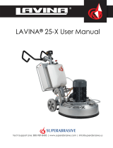
9.2DISMOUNTINGANDMOUNTINGTOOLHOLDERTOCHANGEBUFFERSANDSPIDER,CHANGINGV‐RINGSANDFELT‐RINGS
Tocheckorreplacethebuffersandthespiders,thetoolholderhastoberemoved.Removethecountersunkscrewsontopofthe
buffer(Fig.9.2.1).Takethediscoff(Fig.9.2.2),nowthespidercanberemovedorreplaced(Fig.9.2.3).BylooseningthefourHex
capbolts(Fig.9.2.4),thediscwillcomeloose(Fig.9.2.5)andthebufferscanbereplaced(Fig.9.2.6).Attention,whenmounting
alwaysusethe“blue”threadlockingadhesive,exceptontheboltstolockthebuffers(Fig.9.2.5).Alwaysusetheoriginalbolts.
Dependingonthenumber(3,4,or6)ofbuffers,theholdercanbemoreflexibleorrigid.
Whenthetoolholderisremoved,youcanchangethesealers(V‐RingandFelt‐Ring).
TakeouttheFelt‐Ring,AdaptorandV‐Ring.Beforemountingcheckonwhichsidetheadaptoris
sitting,rememberthecorrectside.MounttheV‐RingwiththesmallestlipoftheVtoinside
(Fig.9.2.7)justpushtheV‐ringsothetopisonthesamelevelasthepulleytop(Fig.9.2.8).
ThentaketheadaptorinthecorrectwayandpushtheV‐Ringdownwiththeadaptor
(Fig.9.2.9).ThelowestlipoftheV‐Ringshouldonlybarelytouchitsglidingsurface;alsonever
pushtheV‐Ringdownwithfingers.MountnowtheFelt‐ringontop(Fig.9.2.10).Closethe
sealerswiththecap(Fig.9.2.11).
Figure 9.2.1 Figure 9.2.2 Figure 9.2.3
Figure 9.2.4 Figure 9.2.5 Figure 9.2.6

Superabrasive UserManual OriginalLanguageLavina®25‐S‐E 8/2014
16
9.3TENSIONINGANDREPLACETHEPLANETARYBELT
Ifthebeltslipsorisbrokenseparatethecarriage
fromthemainhead,pulloutthemotor
plug(Fig.9.3.1),water‐(Fig.9.3.2)(Fig.9.3.3),and
vacuumtubes(Fig.9.3.4).Takeoffthehandles,
fork,topframe,andweightholderssoyoucan
dismountthetopcover(Fig.9.3.5).
9.4TENSIONINGUSEDPLANETARYBELT
Anoticeablelossofspeedintheplanetarymovementmeansthebeltmayneedtobetensioned,see9.5
Mountingandtensioninganewplanetarybelt.
9.5MOUNTINGANDTENSIONINGANEWPLANETARYBELT
Figure 9.4.1 Figure 9.4.2
Figure 9.5.6
Figure 9.5.1
Figure 9.5.4
Figure 9.5.2 Figure 9.5.3
Figure 9.5.5
Figure 9.3.1 Figure 9.3.3
Figure 9.3.2
Figure 9.3.5
Figure 9.3.4

Superabrasive UserManual OriginalLanguageLavina®25‐S‐E 8/2014
17
Completelyremovethetensioningdevice(Fig.9.5.1).Make2signsonthedismountedbelt
thatareexactly10cmfromeachother(beltwithouttension)(Fig.9.5.2).Thepurposeisto
measure10.2cmonthebeltwhentensioned.ATTENTION:NEVER“OVER”TENSIONTHE
BELT,THEBELTWILLBEDAMAGEDANDITWILLNEVERRECOVERFROMITSORIGINAL
TENSION
Mountthebeltbackaroundtheplanetarypulley;seethatthebeltisbehindthedrivingpulley
(Fig.9.5.3).Putthebeltaroundtheleftrollerofthetensioningdevice(Fig.9.5.4).Putthe
tensioningdevicebackinplaceandpullthebeltfromtherollerontherightside(Fig.9.5.5).
Putthebeltaroundthedrivingpulley(Fig.9.5.6).Begintotensionuntiltheprevious10cm
measurementequals10.2cm(Fig.9.5.7andFig.9.5.8).Tightenthetensioningdevicewhile
turningtheboltandmovingtheplanetaryheadsothebeltcanslide(Fig.9.5.8).Donotforget
tolockthetensioningdevice(Fig.9.5.9).
9.6CHECKINGTHETENSIONOFTHEBELT
Openthecheckingcovertoreachthebeltandtensiondevice(Fig.9.6.1).
Whiletensioning,besuretoregularlycheckthetension.Pushthebelt
downwithapressureof71N.Thisisapproximately7kilogramsor15
pounds;withthispressurethebeltshouldmove3.5‐4mmor1/8”.Itis
recommendedthatthetensioningofthebeltbemeasuredwithOptikrik
IIDevice(Measuringrange:500‐1400N)(Fig.9.6.2).Theoriginal
pressureP=1400NandafterworkingawhileisP=1100N.
ATTENTION:NEVER“OVER”TENSIONTHEBELT,THEBELTWILLBE
DESTROYEDANDITWILLNEVERRECOVERITSORIGINALTENSION
Loosenthecontranuts(Fig.9.6.3),lightlyloosenthethreeboltsofthe
tensiondevice(Fig.9.6.4),andadjustthetensionwiththenutseenin
(Fig.9.6.5).Whentherighttensionisreached:closethecontranutsandthethreeboltsofthesupport.Reassembleinthesame
manner.
PLEASEMAKESUREYOUCHECKTHETENSIONOFTHEBELTAFTERTHEFIRST15HOURSOFOPERATION
Figure 9.5.7 Figure 9.5.8 Figure 9.5.9
Figure 9.6.3
Fi
g
ure 9.6.2
Figure 9.6.1
Figure 9.6.4
Figure 9.6.5

Superabrasive UserManual OriginalLanguageLavina®25‐S‐E 8/2014
18
9.7REPLACINGTHEPULLEYUNITS
Dismountguardandtopcoveraspreviousdescribed.
Dismountingthedrivingpulley:takethetopscrewouttoreleasethebushing(Fig.9.7.1),pushthebushingtogetherwiththe
washerup(Fig.9.7.2),pushwasherdownofthebushing(Fig.9.7.3).,takebushingout(Fig.9.7.4),pushkeyout(Fig.9.7.5),nowthe
washerreleases(Fig.9.7.6),dismountsealercap(Fig.9.7.7)(Fig.9.7.8),thepulleycanbereleasedwithtwocrowbarsbutdonotuse
excessiveforce(Fig.9.7.9),pushthesealercaptodismount(Fig.9.7.10),bymountingbacksecurewithsealant(Fig.9.7.11),center
theholestomountthepulley(Fig.9.7.12).
Figure 9.7.10
Figure 9.7.7 Figure 9.7.8 Figure 9.7.9
Figure 9.7.12
Figure 9.7.11
Figure 9.7.6
Figure 9.7.5
Figure 9.7.2
Figure 9.7.1
Figure 9.7.4
Figure 9.7.3
Figure 9.7.13 Figure 9.7.15 Figure 9.7.14

Superabrasive UserManual OriginalLanguageLavina®25‐S‐E 8/2014
19
Forthetwootherpulleys,loosethefiveboltsofeachpulleybetweenthebaseplateandthemotorbasedisc(Fig.9.7.13).Anoil
sealring(Fig.9.7.14)andaseal(Fig.9.7.15)shouldbeplacedontopofthepulleybeforemounting.
9.8MOUNTINGTHEBELT
Seeheretheschematicofthebeltonthepulleys(Fig.9.8.1).
Todismount/mountthebelt,followthetensioninginstructioninchapter:
Checkingthetensionofthebelt.
9.9MOTORCONNECTION
Incasethemotorisbeingreplaced,pleasefollowthecableconnectionsinthefiguresbelow(Fig.9.9.1).
Lavina®25‐S‐E
Themotorisconnectedin“Star”
380Volt,reminderforthe
wireconnectionofthemotor.
Figure 9.9.1
Figure 9.8.1

Superabrasive UserManual OriginalLanguageLavina®25‐S‐E 8/2014
20
9.10FAULTDIAGNOSISINVERTERYASKAWAV1000
Pagesarereferringto
YaskawaElectricSIEPC71060618AYASKAWAACDrive–V1000TechnicalManual
/