
Manufactured By
H&S MANUFACTURING CO.,INC.
P.O. BOX 768 (715) 387-3414 FAX (715) 384-5463
MARSHFIELD, WISCONSIN 54449
WARNING
READ AND UNDERSTAND THIS MANUAL
BEFORE OPERATING THIS EQUIPMENT.
UNSAFE OPERATION OR MAINTENANCE OF
THIS EQUIPMENT CAN RESULT IN SERIOUS
INJURY OR DEATH.
HSMFG1012 Part #59781
430W430W
430W430W
430W
MANURE SPREADERMANURE SPREADER
MANURE SPREADERMANURE SPREADER
MANURE SPREADER
OPERAOPERA
OPERAOPERA
OPERATT
TT
TOR’S MANUOR’S MANU
OR’S MANUOR’S MANU
OR’S MANUALAL
ALAL
AL
Revision #1
430W Starting Serial #317196

CONTENTS
Warranty & Warranty Registration Card . . . . . . . . . . . . . . . . . . . . . . . . . . . . . . . . . . . . . . . . . . . . . . . 1-2
Dealer Pre-Delivery Checklist . . . . . . . . . . . . . . . . . . . . . . . . . . . . . . . . . . . . . . . . . . . . . . . . . . . . . . . . . 3
Dealer Delivery Checklist . . . . . . . . . . . . . . . . . . . . . . . . . . . . . . . . . . . . . . . . . . . . . . . . . . . . . . . . . . . . . 5
Safety Information - Be Alert Symbol . . . . . . . . . . . . . . . . . . . . . . . . . . . . . . . . . . . . . . . . . . . . . . . . . . . . 7
Safety Information - Explanation of Safety Signs . . . . . . . . . . . . . . . . . . . . . . . . . . . . . . . . . . . . . . . . . . 8
Safety Decals . . . . . . . . . . . . . . . . . . . . . . . . . . . . . . . . . . . . . . . . . . . . . . . . . . . . . . . . . . . . . . . . . . . . 9-10
Safety Information - Warning - Owner Must Read and Understand . . . . . . . . . . . . . . . . . . . . . . . . . . . 11
Cap Screw Torque Values . . . . . . . . . . . . . . . . . . . . . . . . . . . . . . . . . . . . . . . . . . . . . . . . . . . . . . . . . . . . 12
Set-Up & Assembly . . . . . . . . . . . . . . . . . . . . . . . . . . . . . . . . . . . . . . . . . . . . . . . . . . . . . . . . . . . . . . . . . 13
Transporting . . . . . . . . . . . . . . . . . . . . . . . . . . . . . . . . . . . . . . . . . . . . . . . . . . . . . . . . . . . . . . . . . . . . . . . . 13
Preparing for Operation . . . . . . . . . . . . . . . . . . . . . . . . . . . . . . . . . . . . . . . . . . . . . . . . . . . . . . . . . . . . . . 14
Operation . . . . . . . . . . . . . . . . . . . . . . . . . . . . . . . . . . . . . . . . . . . . . . . . . . . . . . . . . . . . . . . . . . . . . . . 15-16
Adjustments . . . . . . . . . . . . . . . . . . . . . . . . . . . . . . . . . . . . . . . . . . . . . . . . . . . . . . . . . . . . . . . . . . . . . 17-18
Service . . . . . . . . . . . . . . . . . . . . . . . . . . . . . . . . . . . . . . . . . . . . . . . . . . . . . . . . . . . . . . . . . . . . . . . . . . . . 19
Optional Equipment . . . . . . . . . . . . . . . . . . . . . . . . . . . . . . . . . . . . . . . . . . . . . . . . . . . . . . . . . . . . . . 20-21
Lubrication Guide . . . . . . . . . . . . . . . . . . . . . . . . . . . . . . . . . . . . . . . . . . . . . . . . . . . . . . . . . . . . . . . . 22-23
Decal Location . . . . . . . . . . . . . . . . . . . . . . . . . . . . . . . . . . . . . . . . . . . . . . . . . . . . . . . . . . . . . . . . . . 25-27
Trouble Shooting . . . . . . . . . . . . . . . . . . . . . . . . . . . . . . . . . . . . . . . . . . . . . . . . . . . . . . . . . . . . . . . . . . . . 24
Service Notes . . . . . . . . . . . . . . . . . . . . . . . . . . . . . . . . . . . . . . . . . . . . . . . . . . . . . . . . . . . . . . . . . . . . . . . 28
Specifications . . . . . . . . . . . . . . . . . . . . . . . . . . . . . . . . . . . . . . . . . . . . . . . . . . . . . . . . . . . . Inside Back Cover


DEALER PRE-DELIVERY CHECK LIST
AFTER COMPLETION, DEALER SHOULD REMOVE AND RETAIN FOR RECORDS
After the Manure Spreader has been completely set-up, check to be certain it is in correct operating
order before delivering to the customer. The following is a list of points to inspect. Check off each item
as you have made the proper adjustments and found the item operating satisfactorily.
Manure Spreader was not damaged in shipment. Check for dents and loose or missing
parts. Report damage immediately to H&S Manufacturing Co., Inc.
Manure Spreader has been correctly assembled according to instructions in this manual.
All bolts and fasteners are tight.
All shields and guards are in place and secured.
All grease fittings have been lubricated. Gearbox is filled to proper levels.
See Lubrication Chapter of this manual for details.
Hoses and fittings if applicable, are properly attached and there are no visible leaks.
All drive chains are adjusted to proper tension. See Adjustment Chapter of this manual.
Decals are in place and legible.
Connect the Manure Spreader to a tractor and attach the PTO and make sure that the
PTO guards turns freely.
Connect the lights to the tractor if applicable. Lights and wiring functioning properly.
Run the Manure Spreader and make sure all components operate properly.
Hydraulic system if applicable, does not leak under pressure.
-3-
(Remove Dealer File Copy At Perforation)
Model Number ______________________________________________
Serial Number ______________________________________________
Dealer’s Name ________________________________________________________________
Inspection Date _____________________________________________
Signature of Pre-Delivery Inspector ________________________________________________

-4-
Intentionally Left Blank

AFTER COMPLETION, DEALER SHOULD REMOVE AND RETAIN FOR RECORDS
Note: Warranty is not valid until warranty card is completed and returned to H&S Mfg. Co., Inc.
(Remove Dealer File Copy At Perforation)
-5-
DEALER DELIVERY CHECK LIST
This check list that follows is an important reminder of valuable information that should be passed
on to the customer at the time this Manure Spreader is delivered.
Check off each item as you explain it to the customer.
This delivery check list, when properly filled out and signed assures the customer that the
pre-delivery service was satisfactorily performed.
Explain to the customer that the pre-delivery inspection was made.
Explain to the customer all the safety precautions they must exercise when operating
this unit.
Explain recommended loads for different types of materials.
Explain to customer that regular lubrication is required for proper operation and long
life of machine.
Show customer the lubrication section of Owner’s Manual.
Give the customer Owner’s Manual and make sure they read and understand all
operating and service instructions.
Have customer sign a completed “Warranty Registration,” and mail it promptly.
Date Delivered __________________________________
Dealer’s Name ________________________________________________________________
By __________________________________________________________________________
Signature of Original Buyer ______________________________________________________

-6-
Intentionally Left Blank

BE
ALERT! YOUR SAFETY
IS INVOLVED.
THIS SYMBOL IS USED THROUGHOUT THIS BOOK WHENEVER YOUR PERSONAL SAFETY
IS INVOLVED. TAKE TIME TO BE CAREFUL. REMEMBER: THE CAREFUL OPERATOR IS THE
BEST OPERATOR. MOST ACCIDENTS ARE CAUSED BY HUMAN ERROR. CERTAIN
PRECAUTIONS MUST BE OBSERVED TO PREVENT THE POSSIBILITY OF INJURY OR
DAMAGE.
-7-
H&S MANUFACTURING CO., INC.
SAFETY INFORMATION

-8-
RECOGNIZE SAFETY INFORMATION
This is the safety-alert symbol. When you see this
symbol on your machine or in this manual, be alert to the
potential for personal injury.
Follow recommended precautions and safe operating
practices.
UNDERSTAND SIGNAL WORDS
A single word; DANGER, WARNING, or CAUTION is used
with the safety-alert symbol. DANGER identifies the most
serious hazards.
Safety signs with signal word DANGER or WARNING are
typically near specific hazards.
General precautions are listed on CAUTION safety signs.
FOLLOW SAFETY INSTRUCTIONS
Carefully read all safety messages in this manual, and all safety signs on your machine. Follow all
recommended precautions and safe operating procedures.
OBSERVE MAXIMUM TRANSPORT SPEED
The maximum transport speed for this implement is 32 km/h (20 m.p.h.).
Some tractors are capable of operating at speeds that exceed the maximum
transport speed of this implement. Regardless of the maximum speed capability
of the tractor being used to tow this implement, do not exceed the implement’s
maximum transport speed.
Exceeding the implements maximum transport speed can result in:
* Loss of control of the tractor/implement combination
* Reduced or no ability to stop during braking
* Implement tire failure
* Damage to the implement structure or its components
Use additional caution and reduce speed when towing under adverse surface
conditions, when turning, and when on inclines.
Do not attempt transport if the fully loaded implement weighs more than 1.5 times
the weight of the tractor.
Keep signs in good condition. Immediately replace any missing or damaged signs.
SAFETY INFORMATION

-9-
SAFETY INFORMATION

-10-
SAFETY INFORMATION

-11-
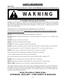
WARNING
TO PREVENT SERIOUS INJURY OR DEATH
Study The Above Safety Rules
ATTENTION - BE ALERT - YOUR SAFETY IS INVOLVED
BEFORE YOU ATTEMPT TO OPERATE THIS EQUIPMENT, READ AND STUDY THE FOLLOWING
INFORMATION. IN ADDITION, MAKE SURE THAT EVERY INDIVIDUAL WHO OPERATES OR WORKS
WITH THIS EQUIPMENT, WHETHER FAMILY MEMBER OR EMPLOYEE, IS FAMILIAR WITH THESE
SAFETY PRECAUTIONS.
KNOW HOW TO STOP UNLOADING MECHANISM BEFORE STARTING IT.
If the machine becomes clogged, disengage the PTO. Stop the tractor engine, remove ignition key,
and allow all mechanisms to stop before cleaning or working on the machine.
DO NOT get off the tractor while the Manure Spreader is in operation.
DO NOT attempt to perform maintenance or repair with tractor running and PTO or hydraulic lines
hooked up.
DO NOT step up on machine at any time.
NEVER manually feed material into the beaters.
DO NOT allow minors to operate or be near the machine.
DO NOT ALLOW PERSONNEL OTHER THAN THE QUALIFIED OPERATOR NEAR THE MACHINE.
Before starting tractor, be sure PTO shields turn freely and PTO is securely locked to tractor.
DO NOT clean, adjust, or lubricate the machine when any part is in operation.
Keep hands, feet, and clothing away from beaters when they are revolving.
Loose or floppy clothing should not be worn by the operator.
Be sure the machine is clear of people, tools, and other objects before engaging PTO.
DO NOT step over power take off shaft. Stay clear of PTO at all times.
NEVER start Manure Spreader until all guards and safety shields are secured in place.
STAY CLEAR of Hydraulic Lines. They may be under extreme pressure or heat.
H&S always takes the operator and his safety into consideration and guards exposed moving parts for
his protection. However, some areas cannot be guarded or shielded in order to assure proper operation.
In addition, the operators manual and decals on the machine itself warn you of further danger and
should be read and observed closely.
TRACTOR:
This operators manual uses the term “Tractor” when identifying the power or the towing source.
SAFETY INFORMATION

-12-

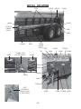
REFLECTORS/SMV
When transporting on the highway, connect the spreader to
the tractor with a lighting power cord. The lighting system
is to be connected to the 7 pin power receptacle (per
SAEJ560B) on your tractor. If your tractor is not equipped
with the proper receptacle, see your tractor dealer for
details. Make sure lights are functioning properly. Regularly
clean the reflective tape at the rear of the spreader. There is
a holder provided for your SMV sign. Unless otherwise
prohibited, use a slow-moving vehicle emblem. Never tow
the manure spreader on a public highway at a speed greater
than 20 m.p.h. (32 kph).
TRANSPORTING
SAFETY CHAIN (Optional)
Follow state and local regulations regarding use of a safety chain and transport lighting when towing farm
equipment on public highways. A proper safety chain should be used to retain the safety connection
between the towing and towed machines, in the event of separation of the primary attaching system.
Check with local law enforcement agencies for your own particular regulations. Never tow the manure
spreader on a public highway at a speed greater than 20 m.p.h. (32 kph).
1. Chain is sufficiently slack to allow turns and movements of either the tractor or the manure spreader,
without placing tension on the chain.
2. Chain is of sufficient strength to hold the decoupled implement (and its load) and tow it to the
shoulder.
SET-UP & ASSEMBLY
Note: Determine right and left side of spreader by viewing it from the rear. If instructions
or parts lists call for hardened bolts, refer to Cap Screw Torque Value page to identify.
-13-
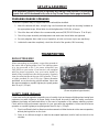
PREPARING MANURE SPREADER
The Manure Spreader may be shipped without the wheels/tires installed.
1. Attach the wheels with tires, using the lug nuts furnished and torque the mounting hardware to
the appropriate torque. Wheel bolts should be tightened at 100 ft./lbs. of torque.
2. Check the tires and inflate to the recommended pressure(295/75RX22.5 tires to 75 to 80 psi.).
3. Check for proper assembly and adjustment and make sure that all bolts are tightened.
4. Securely retighten after a few hours of operation, as bolts can loosen up on new machinery.
5. Lubricate the machine completely, check the oil level of the gearbox, fill if necessary.
(Shown w/optional upper beater)

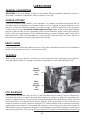
PREPARING FOR OPERATION
Tractor Hitch
Fasten the spreader hitch to the drawbar with a hitch pin with
a safety locking device. Remove the weight from the jack (jack
is not to be used when spreader is loaded). Remove jack from
pipe mount and place on convenient storage mount located on
the top of left hitch channel. This allows protection of jack from
tractor tires during turns. The hitch of the spreader is designed
for a standardized tractor hitch. Adjust the drawbar so that it is
13 to 17 inches above the ground. Extend or shorten it so that
the horizontal distance from the end of the tractor power takeoff
shaft to the center of the hitch pin hole is 14 inches for 540 PTO
and 15-3/4” for 1000 PTO as shown in drawing. An improperly
located hitch point may cause damage to the universal joints of
the power takeoff. Secure the drawbar so that the hitch pin hole
is directly below the power drive line.
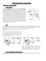
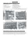
TRACTOR CONNECTIONS
If this implement is attached to a tractor with a clevis
hitch (hammer-strap) style drawbar, the
hammer-strap must be removed to prevent
damage to the IID guarding and the IID telescoping
members. [See Figure 1]
If this implement is attached to a tractor with an
offset in the drawbar, be certain it is in the down
position to prevent damage to the IID guarding and
the IID telescoping members. [See Figure 2]
PTO
Attach the PTO of the spreader to the tractor by sliding the spring loaded locking collar on PTO yoke
rearward, then sliding it onto the tractor PTO shaft. Release spring loaded collar. Be sure the pins fall
into the groove of the tractor PTO shaft and collar snaps forward into locking position.
CAUTION: Do not use a steel hammer to aid in joining PTO parts.
-14-
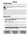
Manure Spreader Speed Control
Attach the manure spreader speed control/beater engage/disengage rope to a convenient point on the
tractor.
15-3/4” for 1000 RPM

High Speed
Low Speed Clean Out
-15-
OPERATION
LOADING
In freezing weather, make certain that hydraulic tail gate (if equipped with one) is not frozen to the sides or
on the floor of the spreader. Make sure the apron chain is not frozen to the spreader floor or any lumps of
manure are frozen to the floor. Begin loading the spreader at the front end and work toward the rear until
loading is completed. Loading this way permits the material to be spread uniformly. Loading front to rear
is particularly important when the spreader is loaded by a mechanical loader because this type of load
requires more power to spread than others loads. When hauling extremely heavy materials with a large
portion of dirt, it may be necessary to reduce the load size to prevent excessive shear bolt breakage.
Never dump material onto the beater. Do not use extra sideboards. Do not overload spreader.
Overloading decreases spreading effectiveness. Do not load more than 15 inches above the beater.
SPREADING - 2 SPEED
NOTE: Two speed drive mechanism and beater engage/disengage are controlled be one rope leading to
the tractor.
1. When ready to unload, make sure beater is in the engaged position and low speed indicator is
visible through low speed hole in panel of spreader.
2. Raise the hydraulic endgate.
3. Engage the tractor PTO shaft slowly.
4. Increased apron speed, if desired, can be accomplished by steadily pulling on the rope until it
stops. Speed select indicator should now be visible through the high speed hole. Beater will
continue to operate and apron speed will be increased.
5. When the Manure Spreader is almost empty, the bed can be cleaned by shifting into clean out
position. Apply a steady pull on the rope until it stops and speed indicator is visible in the clean out
hole. In this position, the beater will stop and the apron will continue to operate at the same speed
as in high speed position, thus saving unnecessary driving.
6. When spreader is empty, shut off tractor PTO. Pull control rope until speed select indicator snaps
into low speed. This will re-engage beater for the next load. DO NOT SHIFT FROM CLEAN OUT
TO LOW SPEED WITH THE TRACTOR PTO RUNNING.
7. Do not operate the Manure Spreader with a PTO speed greater than 540 RPM’s unless necessary
sprocket changes have been made.
EMERGENCY SHUTDOWN
If a foreign object becomes lodged in the beater area and shears the shear bolt, disengage the PTO. Stop
the tractor engine, remove the ignition key, and allow all mechanisms to stop before cleaning or working
on the spreader.
WARNING: Some photographs used in the following pages show guards or shields
removed for clarification. NEVER operate machine until these guards or shields are in
proper operating position.

SPREADING - WITH OPTIONAL HYDRAULIC DRIVE
1. Engage tractor PTO shaft slowly. Beater is always in the engaged position, therefore, engaging
tractor PTO will automatically start beater.
2. Raise the hydraulic tailgate.
3. Open hydraulic valve on tractor connected to speed control valve on Manure Spreader.
4. Control speed of apron by turning speed control handle clockwise to increase speed,
counter-clockwise to decrease speed.
5. When the Manure Spreader is almost empty, the bed can be cleaned out by disengaging tractor
PTO (which will stop beater), and increasing apron speed by turning control handle clockwise,
thus saving unnecessary driving time.
OPERATION
FAILURE TO FOLLOW THE RECOMMENDED ADJUSTMENTS WILL VOID WARRANTY
-16-

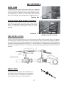
DRIVE CHAIN
To adjust front drive chain, loosen jam nut turn nut on adjusting
rod (located at the right hand front side of spreader) clockwise.
There should be 1/2” deflection at the center of the drive chain.
Over tightening or too loose of a chain will result in excessive
wear on the bearing, chain and sprockets. Retighten jam nut.
Tightener Bolt
-17-
ADJUSTMENTS
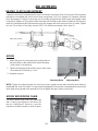
APRON SPEED AND BEATER CONTROL
One cable controls both the beater clutch and two speed
clutch. To compensate for wear or stretching of this cable,
adjust the turnbuckle behind shield at the front of the
spreader.
TWO SPEED CLUTCH
If clutch control yoke becomes worn, it may be necessary to adjust the high speed clutch so it engages
and disengages completely. Adjustment to compensate for this wear is made by sliding spring stop (A)
on control rod closer to the clutch engaging lever. Initial adjustment should be made as follows: Distance
(B) between spring stop and jam nut is seven (7”) inches. Distance (C) between jam nut and shifting rod
bracket is one-eighth (1/8”) inches. This distance may be achieved by adjusting the turnbuckle at front of
spreader.
Shields Removed for Clarity
Turnbuckle
WHEEL HUBS
To adjust wheel hubs, tighten the castellated nut on
the spindle to the point where there is no end-play
and a slight drag on the bearings. Replace the
cotter key with a new one of the correct size.

APRON WORM DRIVE CHAIN
The apron worm drive chains are kept tight
with a spring type tightener that does not
require adjustment. However, periodic
inspection should be made to check for wear.
Mounting Bolts Adjusting Bolt
APRON
1. Adjust the apron by loosening the mounting bolts on
the chain slides on the outside of the frame. Mounting
bolts shown in the drawing.
2. Tighten the adjusting bolts until the apron chain clears
the underside of the axle by 1 inch.
3. Retighten jam nut.
ADJUSTMENTS
NOTE: Tighten the adjusting bolts (on each front corner) equally on each side so that the apron slats run
parallel with the ends of the bed. The apron will be damaged if the machine is operated with one end of the
apron slats running ahead of the opposite end. Do not tighten the apron chains excessively.
-18-
BEATER CLUTCH ADJUSTMENT
It may be necessary to compensate for wear in the beater clutch and clutch control yoke. When properly
adjusted the moveable jaw clutch should have one-quarter (1/4”) inch (distance C) between clutches
when disengaged. To adjust, loosen jam nut (A) holding spring bracket. With beater disengaged (clean
out position), tighten nut (B) against shifter lever bracket until the proper distance between clutch jaws is
reached. Overtightening will cause beater not to fully engage and cause excess tension on cable. Tighten
lock nut (D) so there is one thirty-second (1/32”) inch clearance between clutch jaws (E).
Page is loading ...
Page is loading ...
Page is loading ...
Page is loading ...
Page is loading ...
Page is loading ...
Page is loading ...
Page is loading ...
Page is loading ...
Page is loading ...
Page is loading ...
Page is loading ...
-
 1
1
-
 2
2
-
 3
3
-
 4
4
-
 5
5
-
 6
6
-
 7
7
-
 8
8
-
 9
9
-
 10
10
-
 11
11
-
 12
12
-
 13
13
-
 14
14
-
 15
15
-
 16
16
-
 17
17
-
 18
18
-
 19
19
-
 20
20
-
 21
21
-
 22
22
-
 23
23
-
 24
24
-
 25
25
-
 26
26
-
 27
27
-
 28
28
-
 29
29
-
 30
30
-
 31
31
-
 32
32


Ask a question and I''ll find the answer in the document
Finding information in a document is now easier with AI
Related papers
-
 H&S SW3143 Operating instructions
-
 H&S S3237 Operating instructions
-
 H&S S3143 Operating instructions
-
 H&S MS310 Operating instructions
-
 H&S SW3243 Operating instructions
-
 H&S S3237 Operating instructions
-
 H&S 2217 User manual
-
 H&S S2280 User manual
-
 H&S S3127 Operating instructions
-
 H&S S3127 Operating instructions


Other documents
-
 ABI Attachments 50-125 User guide
-
 Roda 810 User manual
-
Wallenstein MX Series Manure Spreader User manual
-
 ABI Attachments abi Classic Spreader 185 Cu. Ft. User guide
-
 Millcreek 8700P User manual
-
Meyer 8720 User manual
-
-
-


