Page is loading ...

1 - M/B 9999 (Multi-gauge Set) Intellitronix (rev.6/2022) www.intellitronix.com
Made in America Lifetime Guarantee
Thank you for purchasing this instrument set from Intellitronix. We value our customers!
INSTALLATION GUIDE
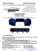
Multi-Gauge Set with sending units
Part Number: M/B 9999
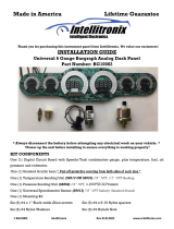
* Always disconnect the battery before attempting any electrical work on your vehicle.*
Parts included in this package -
◊ Fuel Level Gauge
◊ Oil Pressure Gauge and sending unit
◊ Speedometer and sending unit
◊ Tachometer
◊ Voltmeter
◊ Water Temperature Gauge and sending unit
GENERAL WIRING INSTRUCTIONS
Note: Automotive circuit connectors are the preferred method of connecting wires. However, you may
solder if you prefer.
Voltmeter
Ground - Black Connect directly to an engine ground such as the engine block. For the most
accurate readings, connect to the same ground as the sending unit.
Power - Red Connect to a switched +12V source such as the ignition switch.
Note: The device will NOT function properly without a steady +12V source. For best results use a multimeter
to test the power source.
Dimmer – Purple Connect to the parking lights to dim the LEDs 50% when the headlights are
on. However, do not connect to the headlight rheostat control wire; as the dimming feature will
not work properly. Otherwise, connect to ground for permanent 100% brightness.
Fuel Level Gauge
Fuel - Yellow Connect to the output of the vehicle’s existing sending unit.
Ground – Black/Yellow connect to fuel sending unit ground
*This will not apply to Bar Graph style gauges
Model
Resistance
Wire(s) to cut
Ford/Chrysler
73 to 10 OHM
NONE
GM
0 to 90 OHM
Blue
VDO
10 to 180 OHM
Blue & Orange
Universal
240 to 33 OHM
Orange

2 - M/B 9999 (Multi-gauge Set) Intellitronix (rev.6/2022) www.intellitronix.com
Oil Pressure Gauge
Ground - Black Connect directly to an engine ground such as the engine block. For the most
accurate readings, connect to the same ground as the sending unit.
Power - Red Connect to a switched +12V source such as the ignition switch.
Note: The device will NOT function properly without a steady +12V source. For best results use a multimeter
to test the power source.
Dimmer – Purple Connect to the parking lights to dim the LEDs 50% when the headlights are
on. However, do not connect to the headlight rheostat control wire; as the dimming feature will
not work properly. Otherwise, connect to ground for permanent 100% brightness.
Oil Pressure – Orange - Replace the existing oil pressure sending unit with the unit included with
your gauge. The Orange wire will be wired to the S terminal on the sending unit. This gauge is
incompatible with other sending units.
Oil Pressure – Orange/black or Brown/Black- From the G terminal on sender will be wired to
ground on the engine block using 18 Ga wire to ensure proper ground!
Water Temperature Gauge
Ground - Black Connect directly to an engine ground such as the engine block. For the most
accurate readings, connect to the same ground as the sending unit.
Power - Red Connect to a switched +12V source such as the ignition switch.
Note: The device will NOT function properly without a steady +12V source. For best results use a multimeter
to test the power source.
Dimmer – Purple Connect to the parking lights to dim the LEDs 50% when the headlights are
on. However, do not connect to the headlight rheostat control wire; as the dimming feature will
not work properly. Otherwise, connect to ground for permanent 100% brightness.
Water – Blue - This gauge is incompatible with other sending units, so you must replace the existing
water temperature sending unit with the included sender. Do not use Teflon tape or other sealer on
the new sending unit’s threads to avoid inaccurate readings. Connect the blue wire to the sending
unit. For best results we suggest running a new wire.
NOTE: THE FOLLOWING INSTRUCTION ONLY PERTAINS TO THE TWO TERMINAL SENDER AND
CIRCUIT BOARDS THAT ARE WIRED FOR THIS SENDER. NOT ALL KITS WILL CONTAIN A TWO
TERMINAL SENDER.
Water –Black/ Blue - This is a ground wire for the two terminal water temp sender. If your dash kit
came with the single terminal sender this wire will go to the engine block ground. If using the two
terminal sender this will go to the black/blue wire on the sender’s harness. If your kit contains a two
wire sender and your dash circuit board does not have the Black/Blue wire installed then run this wire
coming off the senders harness to the same ground that the dash board is grounded too.

3 - M/B 9999 (Multi-gauge Set) Intellitronix (rev.6/2022) www.intellitronix.com
Speedometer
This speedometer requires a pulse generating electronic speed sensor or a transmission with an
electronic output. If a cable drives the current speedometer in your vehicle, please order our
electronic sensor (S9013) for GM and universal applications or (S9024) for Ford transmissions.
Ground - Black Connect directly to an engine ground such as the engine block. For the most
accurate readings, connect to the same ground as the sending unit.
Power - Red Connect to a switched +12V source such as the ignition switch.
Note: The device will NOT function properly without a steady +12V source. For best results use a multimeter
to test the power source.
Dimmer – Purple Connect to the parking lights to dim the LEDs 50% when the headlights are
on. However, do not connect to the headlight rheostat control wire; as the dimming feature will
not work properly. Otherwise, connect to ground for permanent 100% brightness.
SPEEDOMETER (you have three methods for speedometer connection)
1.) Speedometer – White - (Factory sender with Powertrain Control Module) When using a LS
engine swap, you will need to pick up the Speedometer signal wire from the PCM Pin 50 on the red
connector. (This pin may Differ. Refer to your vehicles Pinout Chart for accuracy). Any other
Computer based engine will need to use to use the PCM/ECM to run the speed signal for the
Speedometer. (Consults Pinout Chart)
2.) Speedometer – White - (Factory two wire sender no PCM) - Most vehicles built after 1984 have
an electronic transmission sender. If your vehicle is already equipped with an electronic
transmission, then the electronic vehicle sender will usually have Two wires attached to it. One
connects to the Signal wire on dash (we prefer this to be high output). The other wire (Low output)
Ground at the Engine block. To find High and Low output wire color or pin location will need to be
looked up by Vehicle vin or Model and year or (Consults Pinout Chart).
3.) Speedometer - White (Intellitronix Speed Sender) - Disconnect the mechanical speedometer
cable from the transmission and thread the new electronic sensor onto the transmission. This panel
comes with a 3-wire sensor. If you are using this sensor, the white wire is the speed signal; connect
this to the speed signal wire on your gauge. The red and black wires in the cable are switch power
(12VDC) and ground, respectively. NOTE:(Twist all Three wires together and this will provide an
additional level of interference protection.) The speed signal wire should not be
CALIBRATION
Note: If using the Intellitronix GPS Sending Unit (not included), the speedometer does not need to be
calibrated.
The speedometer leaves the factory with a pre-set industry standard setting of 8,000 pulses per
mile. Chances are that you may not need to recalibrate your speedometer, unless you have
changed the original tire size or the rear end gear ratio.
Note: Do not attempt to recalibrate your speedometer until after it is working properly and you have
determined that the speed is incorrect. The calibration procedure will NOT correct a faulty installation or
improper wiring. If you attempt to recalibrate your speedometer without making sure the speedometer is
receiving pulses from the sending unit, the speedometer will display ‘Err’ and default back to the factory
settings.
To calibrate:

4 - M/B 9999 (Multi-gauge Set) Intellitronix (rev.6/2022) www.intellitronix.com
1. Locate a measured mile where you can safely start and stop your vehicle. By
running the vehicle over this measured distance, the speedometer will learn the
number of pulses outputted by the speedometer sensor during a specific measured
distance. It will then use this acquired data to calibrate itself for accurate reading. There
is a small recall push-button in the center of the panel used to calibrate and read all of
the data stored in the speedometer. After installing your speedometer according to the
wiring instructions, when the ignition is on it should immediately display the default
screen of 0 MPH, if the vehicle is not moving.
2. Stop at the beginning of the measured mile with your vehicle running and in odometer
mode (NOT trip mode), press and hold the push-button until the odometer displays
‘HISP’. On its own, the gauge will then cycle through the recorded performance in the
following order: ‘0 – 60’, ‘1/4’, ‘ODO’, and ‘CAL’.
3. While ’CAL’ is displayed, quickly tap the push-button once. This will put the
speedometer in Program Mode. If you did not tap while ‘CAL’ is displayed, the pulses
per mile will be displayed on the odometer and the display will go back to MPH mode.
Otherwise, you will now see ‘CAL’ displayed along with the number ‘0’. This indicates
that the microprocessor is now ready for calibration.
4. When you are ready, begin driving on the metered mile. You will notice that the
reading will start counting up. The odometer will begin to display the incoming pulse
count. Drive the vehicle through the measured mile (speed is not important, only the
distance traveled).
5. At the end of the mile, stop and press the push-button again. The odometer will now
display the new number of speedometer pulses that were registered over the distance.
The odometer will continue to display the pulse reading for a few seconds. Once it
reverts to the default mode, you have successfully calibrated your speedometer.
Warning: If, while in ‘CAL’ mode, you do not move the vehicle and press the button
again, the microprocessor will NOT have received any data and the unit will display
‘Err’ and will revert to the factory settings. At a minimum, drive some distance and
return to the start if necessary. If you miss stopping the display at ‘CAL’, simply repeat
the steps.
Trip Distance
A single tap of the recall button will activate the trip meter in the odometer display. A decimal
point will appear which will indicate that you are in trip meter mode. Holding the recall button will
clear out the trip distance. To return to the default odometer display, tap the recall button again.
The decimal point will disappear, indicating that you are back in the default odometer display.
Setting the Odometer
While scrolling through ‘CAL’ mode you will see ‘ODO’ appear. This will allow you to enter the
vehicle’s actual mileage. Press the trip button again at this point and you will enter the odometer
set up mode. Press quickly to change the number of the digit on the right. Press and hold to
advance to the next digit. Do this for all 5 digits. For Example: To enter the mileage reading
23456 into the odometer, at the ‘ODO’ prompt, tap the small black button (quickly) two times,
until the number 2 is displayed. Then press and hold the button until the numbers 20 are
displayed. Tap the button 3 times until 23 is displayed. Press and hold the button until 230 is
displayed, and continue in this manner until 23456 is displayed. The speedometer will advance to
the home screen, five seconds after the last number is entered.

5 - M/B 9999 (Multi-gauge Set) Intellitronix (rev.6/2022) www.intellitronix.com
Recording and Viewing Performance Data
Follow these steps to record and recall Performance Data (high speed, ¼mile ET, and 0-60 time):
1. Before each run, your car must be at a complete stop at the starting position. Press and
hold the push-button as it cycles through the performance data. At the end, the odometer
will reset and all performance data will be cleared. This will not affect your stored
calibration value or the odometer reading.
2. Press the push-button until ‘HI-SP’ is displayed. The gauge will automatically cycle
through the performance data.
3. Start the run, pass, session, etc., as mentioned above.
4. When finished, repeat Step 2 to view the data gathered from the run. While stopped, you
can view this data as often as you wish. However, once it finishes scrolling one time, the
memory is ready to record new data and will begin recording again once the vehicle
starts to move. The highest speed measured over multiple runs will be retained in
memory.
TACHOMETER INSTRUCTIONS
Ground – Black--This is the main ground for the display system. A wire should be run from
this board to the vehicle engine block for the best ground. Use 18 AWG or larger wire to
ensure sufficient grounding. Proper vehicle grounding is extremely important for any gauges (or
electronics) to operate correctly. The engine block should have heavy ground cables to the
battery, frame, and firewall. Failure to properly ground the engine block, senders, or digital dash
can cause incorrect or erratic operation.
Power – Red - Connect the power terminal to accessory +12V power from the fuse panel or
vehicle wiring harness. This terminal should have power when the key is on or in accessory
position. Use 18 AWG wire to ensure the system receives a sufficient power feed
Dimmer – Purple Connect to the parking lights to dim the LEDs 50% when the headlights are on.
However, *DO NOT * connect to the headlight rheostat control wire, or the dimming feature will
not work properly and may cause damage to Unit.
Note: If doing a LS engine swap, pick up the tach signal wire from the ECM/ECU and then set
the tach switch to 4-cylinders. You may also need to order the Intellitronix LS Engine Swap
Adapter Kit – for Series 1, 2 and 3 engines. The part number is 8014LS. If you are getting the tach
signal from the ECU, the resistor in the adapter kit will help pull a stronger signal for the
tachometer.
Tachometer – Green
If your vehicle has a separate ignition coil, connect the green wire to the negative (-) side of the
coil – the wire that goes to the points or electronic ignition module.
To ensure that the ignition system does not interfere with any other dashboard functions, do not
run the tachometer wire alongside any other sender or input wires. Do not use solid core spark
plug wires with this dashboard system. Solid core ignition wires cause a large amount of
electromagnetic and radio frequency interference which can disrupt the system’s operation.

6 - M/B 9999 (Multi-gauge Set) Intellitronix (rev.6/2022) www.intellitronix.com
If your vehicle has a GM HEI ignition, connect to the terminal marked ‘TACH’, or, on some
systems, a single white wire with a spade terminal.
If your vehicle has an after-market ignition – some systems will connect to the TACH output
terminal.
If your vehicle has a Computer controlled ignition system, consult the service manual for the
wire color and location.
If your vehicle has a magneto system, connect the tach signal wire to the negative side of the
coil. Do not connect the tach terminal to the positive (+ or high voltage) side of the ignition coil.
Many tachometers, shift lights or RPM-activated switches will not read directly from a
Magneto, so your installation may need a Magneto Signal Converter to function properly.
The default setting for the tachometer is for an 8-cylinder engine.
To change settings:
The display will stay in Settings Mode until it receives a signal from the ignition system. To
program the unit after starting the engine, shut the engine off and turn on only to the accessory
position.
When in accessory mode, the settings menu will scroll through the settings menu. A light tap on
the button engages the menu system.
1. Sets # of digits in RPM display, using button, display shows: (hundreds) 8800, (tens) 8880, and
(ones) 8888.
2. Sets # of cylinders using button, display shows: 1cy, 2cy, etc.
3. Sets first digit on max RPM on gauge bar display (in thousands) using button, display shows:
1000 to 9990. You will need to hold button till you reach desired range. If you miss range you
will need to go around again.
HIGH RPM RECALL
This tachometer has the ability to recall the highest RPM that your vehicle has obtained since it was
last reset. Press the button and hold in on the gauge to display the recall value. Press and hold for
several seconds to clear memory and reset the recall to “0”.
Note: If doing a LS engine swap, pick up the tach signal wire from the ECM/ECU and then set
the tach switch to 4-cylinders. You may also need to order the Intellitronix LS Engine Swap
Adapter Kit – for Series 1, 2 and 3 engines. The part number is 8014LS. If you are getting the tach
signal from the ECU, the resistor in the adapter kit will help pull a stronger signal for the
tachometer

/