Page is loading ...

APOGEE INSTRUMENTS, INC. | 721 WEST 1800 NORTH, LOGAN, UTAH 84321, USA
TEL: (435) 792-4700 | FAX: (435) 787-8268 | WEB: APOGEEINSTRUMENTS.COM
Copyright © 2022 Apogee Instrument, Inc.
OWNER’S MANUAL
USB QUANTUM SENSOR
Model SQ-420X
Rev: 30-Aug-2022

TABLE OF CONTENTS
Owner’s Manual ............................................................................................................................................................................... 1
Certificates of Compliance............................................................................................................................................................ 3
Introduction.................................................................................................................................................................................. 5
Sensor Models .............................................................................................................................................................................. 6
Specifications................................................................................................................................................................................ 7
Deployment and Installation ...................................................................................................................................................... 10
Software Installation .................................................................................................................................................................. 11
Operation and Measurement ..................................................................................................................................................... 12
Windows Software ..................................................................................................................................................................... 14
Mac Software ............................................................................................................................................................................. 19
Maintenance and Recalibration ................................................................................................................................................. 25
Troubleshooting and Customer Support .................................................................................................................................... 27
Return and Warranty Policy ....................................................................................................................................................... 28

CERTIFICATE OF COMPLIANCE
EU Declaration of Conformity
This declaration of conformity is issued under the sole responsibility of the manufacturer:
Apogee Instruments, Inc.
721 W 1800 N
Logan, Utah 84321
USA
for the following product(s):
Models: SQ-420X
Type: Quantum Sensor
The object of the declaration described above is in conformity with the relevant Union harmonization legislation:
2014/30/EU Electromagnetic Compatibility (EMC) Directive
2011/65/EU Restriction of Hazardous Substances (RoHS 2) Directive
2015/863/EU Amending Annex II to Directive 2011/65/EU (RoHS 3)
Standards referenced during compliance assessment:
EN 61326-1:2013 Electrical equipment for measurement, control, and laboratory use – EMC requirements
EN 63000:2018 Technical documentation for the assessment of electrical and electronic products with
respect to the restriction of hazardous substances
Please be advised that based on the information available to us from our raw material suppliers, the products
manufactured by us do not contain, as intentional additives, any of the restricted materials including lead (see
note below), mercury, cadmium, hexavalent chromium, polybrominated biphenyls (PBB), polybrominated
diphenyls (PBDE), bis (2-ethylhexyl) phthalate (DEHP), butyl benzyl phthalate (BBP), dibutyl phthalate (DBP), and
diisobutyl phthalate (DIBP). However, please note that articles containing greater than 0.1 % lead concentration
are RoHS 3 compliant using exemption 6c.
Further note that Apogee Instruments does not specifically run any analysis on our raw materials or end products
for the presence of these substances, but we rely on the information provided to us by our material suppliers.
Signed for and on behalf of:
Apogee Instruments, August 2022
Bruce Bugbee
President
Apogee Instruments, Inc.

CERTIFICATE OF COMPLIANCE
UK Declaration of Conformity
This declaration of conformity is issued under the sole responsibility of the manufacturer:
Apogee Instruments, Inc.
721 W 1800 N
Logan, Utah 84321
USA
for the following product(s):
Models: SQ-420X
Type: Quantum Sensor
The object of the declaration described above is in conformity with the relevant UK Statutory Instruments and
their amendments:
2016 No. 1091 The Electromagnetic Compatibility Regulations 2016
2012 No. 3032 The Restriction of the Use of Certain Hazardous Substances in Electrical and Electronic
Equipment Regulations 2012
Standards referenced during compliance assessment:
BS EN 61326-1:2013 Electrical equipment for measurement, control, and laboratory use – EMC requirements
BS EN 63000:2018 Technical documentation for the assessment of electrical and electronic products with
respect to the restriction of hazardous substances
Please be advised that based on the information available to us from our raw material suppliers, the products
manufactured by us do not contain, as intentional additives, any of the restricted materials including lead (see
note below), mercury, cadmium, hexavalent chromium, polybrominated biphenyls (PBB), polybrominated
diphenyls (PBDE), bis (2-ethylhexyl) phthalate (DEHP), butyl benzyl phthalate (BBP), dibutyl phthalate (DBP), and
diisobutyl phthalate (DIBP). However, please note that articles containing greater than 0.1 % lead concentration
are RoHS 3 compliant using exemption 6c.
Further note that Apogee Instruments does not specifically run any analysis on our raw materials or end products
for the presence of these substances, but we rely on the information provided to us by our material suppliers.
Signed for and on behalf of:
Apogee Instruments, August 2022
Bruce Bugbee
President
Apogee Instruments, Inc.

INTRODUCTION
Radiation that drives photosynthesis is called photosynthetically active radiation (PAR) and is typically defined as
total radiation across a range of 400 to 700 nm. PAR is often expressed as photosynthetic photon flux density
(PPFD): photon flux in units of micromoles per square meter per second (µmol m-2 s-1, equal to microEinsteins per
square meter per second) summed from 400 to 700 nm (total number of photons from 400 to 700 nm). While
Einsteins and micromoles are equal (one Einstein = one mole of photons), the Einstein is not an SI unit, so
expressing PPFD as µmol m-2 s-1 is preferred.
The acronym PPF is also widely used and refers to the photosynthetic photon flux. The acronyms PPF and PPFD
refer to the same variable. The two terms have co-evolved because there is not a universal definition of the term
“flux”. Some physicists define flux as per unit area per unit time. Others define flux only as per unit time. We
have used PPFD in this manual because we feel that it is better to be more complete and possibly redundant.
Sensors that measure PPFD are often called quantum sensors due to the quantized nature of radiation. A quantum
refers to the minimum quantity of radiation, one photon, involved in physical interactions (e.g., absorption by
photosynthetic pigments). In other words, one photon is a single quantum of radiation.
Typical applications of quantum sensors include incoming PPFD measurement over plant canopies in outdoor
environments or in greenhouses and growth chambers and reflected or under-canopy (transmitted) PPFD
measurement in the same environments.
Apogee Instruments SQ-420X quantum sensors consist of a cast acrylic diffuser (filter), interference filter,
photodiode, and signal processing circuitry mounted in an anodized aluminum housing, and a cable to connect the
sensor to a measurement device. Sensors are potted solid with no internal air space and are designed for
continuous PPFD measurement in indoor or outdoor environments. The signal from the sensor is directly
proportional to radiation incident on a flat surface where the radiation comes from all angles of a hemisphere.

SENSOR MODELS
This manual covers the USB quantum sensor model SQ-420X. Additional models are covered in their respective
manuals.
Model
Signal
SQ-420X
USB
SQ-100X
Self-powered
SQ-202X
0-2.5 V
SQ-204X
4-20 mA
SQ-205X
0-5 V
SQ-421X
SDI-12
SQ-422X
Modbus
A sensor’s model number and serial number are
located near USB connector. If you need the
manufacturing date of your sensor, please contact
Apogee Instruments with the serial number of
your sensor.

SPECIFICATIONS
Calibration Traceability
Apogee SQX series quantum sensors are calibrated through side-by-side comparison to the mean of transfer
standard quantum sensors under a reference lamp. The reference quantum sensors are recalibrated with a 200 W
quartz halogen lamp traceable to the National Institute of Standards and Technology (NIST).
SQ-420X
Resolution
0.1 µmol m-2 s-1
Calibration Factor
Custom for each sensor and stored in the firmware
Calibration Uncertainty
± 5 % (see calibration Traceability below)
Measurement
Repeatability
Less than 0.5 %
Long-term Drift
(Non-stability)
Less than 2 % per year
Non-linearity
Less than 1 % (up to 2500 µmol m-2 s-1)
Response Time
Software updates every second
Field of View
180°
Spectral Range
370 to 650 nm (wavelengths where response is greater than 50 % of
maximum; see Spectral Response below)
Directional (Cosine)
Response
± 5 % at 75° zenith angle (see Cosine Response below)
Temperature Response
-0.04 % per C (see Temperature Response below)
Operating Environment
10 to 60 C; 0 to 100 % relative humidity; can be submerged in water up to
depths of 30 m
Dimensions
24 mm diameter, 33 mm height
Mass
Sensor head weighs 90 g
USB Cable
4.5 m (15 ft)
Current Draw (when
Logging)
61 mA

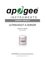
Spectral Response
Mean spectral response of four SQ-100x
series quantum sensors compared to
PPFD weighting function. Spectral
response measurements were made at
10 nm increments across a wavelength
range of 350 to 800 nm in a
monochromator with an attached
electric light source. Measured spectral
data from each quantum sensor were
normalized by the measured spectral
response of the monochromator/electric
light combination, which was measured
with a spectroradiometer.

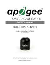
Cosine Response
Mean cosine response of five SQ-
100X series quantum sensors.
Cosine response measurements
were made by direct side-by-side
comparison to the mean of seven
reference SQ-500 quantum
sensors.
Directional, or cosine, response is defined
as the measurement error at a specific
angle of radiation incidence. Error for
Apogee SQ-100X series quantum sensors is
approximately ± 2 % and ± 5 % at solar
zenith angles of 45° and 75°, respectively.

DEPLOYMENT AND INSTALLATION
Mount the sensor to a solid surface with the nylon mounting screw provided. To accurately measure PPFD incident
on a horizontal surface, the sensor must be level. An Apogee Instruments model AL-100 Leveling Plate is
recommended to level the sensor when used on a flat surface or being mounted to surfaces such as wood. To
facilitate mounting on a mast or pipe, the Apogee Instruments model AL-120 Solar Mounting Bracket with Leveling
Plate is recommended.
To minimize azimuth error, the sensor should be mounted with the cable pointing toward true north in the
northern hemisphere or true south in the southern hemisphere. Azimuth error is typically less than 1 %, but it is
easy to minimize by proper cable orientation.
In addition to orienting the cable to point toward the nearest pole, the sensor should also be mounted such that
obstructions (e.g., weather station tripod/tower or other instrumentation) do not shade the sensor. Once
mounted, the blue cap should be removed from the sensor. The blue cap can be used as a protective covering for
the sensor when it is not in use.
Nylon Screw: 10-32x3/8
Model AL-100
Nylon Screw: 10-32x3/8
Model AL-120
Important: Only use the nylon screw provided
when mounting to insulate the non-anodized
threads of the aluminum sensor head from the
base to help prevent galvanic corrosion. For
extended submersion applications, more insulation
may be necessary. Contact Apogee tech support for
details.

SOFTWARE INSTALLATION
The most recent version of ApogeeConnect software can be downloaded at
http://www.apogeeinstruments.com/downloads/.
Installing the software on a PC (Windows compatible, XP and later)
1. Double click on the installer package
2. On the ‘Welcome’ screen, please click ‘Next’ to continue.
3. Select the radio button next to “I Agree” to the UELA… and click ‘Next’ to continue.
4. On the ‘Ready to Install the Program’ screen, click ‘Install’ to continue.
5. Click ‘Finish’ to complete the installation. There are shortcuts on your desktop and in your start bar.
Installing the software on a Mac (Mac compatible, 10.10 and later)
1. Double click on the installer package
2. On the ‘Introduction’ screen, please click ‘Continue’ to proceed.
3. Select ‘Continue’ on the ‘Read Me’ screen to continue, this screen contains a history of updates made to
the ApogeeConnect software versions.
4. Select ‘Continue’ on the ‘License’ screen to receive a prompt to agree to the terms of the software license
agreement. Click ‘Agree’ to continue once you receive the prompt.
5. On the ‘Installation Type’ screen, click ‘Install’ to install the software. You can change the location the
software installs to by clicking ‘Change Install Location…’. *Note: You may be prompted for an
administrator password at this time. If you are, proceed by entering your respective password and clicking
‘Install Software’.
6. Once you receive the message “The installation was successful.” on the ‘Summary’ screen click ‘Close’.
Your software is now ready to be used.

OPERATION AND MEASUREMENT
Spectral Errors
Apogee SQ-100X series sensors can measure PPFD for sunlight and electric light with a single calibration factor.
However, errors occur in various light sources due to changes in spectral output. If the light source spectrum is
known, then errors can be estimated and used to adjust the measurements. The weighting function for PPFD is
shown in the graph below, along with the spectral response of Apogee SQ-100X series quantum sensors. The closer
the spectral response matches the defined PPFD spectral weighting functions, the smaller spectral errors will be.
The table below provides spectral error estimates for PPFD measurements from light sources different than the
calibration source. The method of Federer and Tanner (1966) was used to determine spectral errors based on the
PPFD spectral weighting functions, measured sensor spectral response, and radiation source spectral outputs
(measured with a spectroradiometer). This method calculates spectral error and does not consider calibration,
cosine, and temperature errors.
Federer, C. A., and C. B. Tanner, 1966. Sensors for measuring light available for photosynthesis. Ecology 47:654-
657.
McCree, K. J., 1972. The action spectrum, absorptance and quantum yield of photosynthesis in crop plants.
Agricultural Meteorology 9:191-216.

Underwater Measurements and Immersion Effect
When a quantum sensor that was calibrated in air is used to make underwater measurements, the sensor reads
low. This phenomenon is called the immersion effect and happens because the refractive index of water (1.33) is
greater than air (1.00). The higher refractive index of water causes more light to be backscattered (or reflected)
out of the sensor in water than in air (Smith,1969; Tyler and Smith,1970). As more light is reflected, less light is
transmitted through the diffuser to the detector, which causes the sensor to read low. Without correcting for this
effect, underwater measurements are only relative, which makes it difficult to compare light in different
environments.
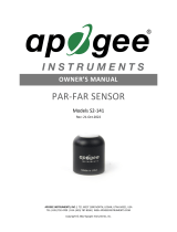
The SQ-420X sensor has an immersion effect correction factor of 1.15. The
immersion effect correction factor can be automatically applied to SQ-420X
measurements by turning on the immersion setting in the settings option of the
ApogeeConnect software, as pictured. Once you are finished making your
underwater measurements simply uncheck the immersion setting in the software,
to turn it off, and continue making measurements in air like normal.
When making underwater measurements, only the sensor and cable can go in the
water. The USB connector is not waterproof and must not get wet.
Further information on underwater measurements and the immersion effect can
be found at http://www.apogeeinstruments.com/underwater-par-
measurements/.

WINDOWS SOFTWARE
When the SQ-420X sensor is not plugged into the USB
port, the software will display a message in the lower left
corner, “Device Not Connected,” indicating it cannot
establish communication with the sensor.
Plug the sensor into a USB port and allow some time
for the sensor to automatically establish
communication with the software. Once established,
the message in the lower left corner will display
“Device Connected SN: ####” and real-time PAR
readings will update on the screen. Moving the sensor
closer to a light source should increase the readings,
while blocking all light from the sensor should drop the
reading to zero.

Click the ‘Settings’ icon to display the software
options.
Clicking ‘Calibration’ will display the factory calibrated
multiplier and offset values. These values are saved in
firmware and can be recovered by clicking the
‘Recover Original’ button. Deriving a new calibration
multiplier and offset is accomplished by clicking the
‘Recalibrate’ button. This is applicable if users want to
calibrate the sensor to their own specific light source.
Note that a reference PAR value of the light source is
required to complete a recalibration.
After clicking the ‘Recalibate’ button the user will be
prompted to cover the sensor. Place a dark cap over the
sensor and wait for the real-time PAR reading to settle
at zero. Click OK.
Uncover the sensor and wait for the PAR reading to
settle before entering the reference value. Click OK.
Clicking ‘Immersion Setting’ will automatically apply
the sensor’s immersion effect correction factor of 1.18
to the sensor measurements. This setting should be
used when the sensor is being used to take
measurements underwater.

The multiplier and offset values will automatically
calculate and update in the appropriate field. Be sure to
click ‘Save’ to retain the new multiplier and offset.
Clicking ‘Data Logging’ will allow the user to log interval
measurements in a csv file while the software is open
and communicating with the sensor.
Click ‘Setup’ and the Setup Logging window appears.
Click the ‘Browse’ button to create or select a csv file.
Select the desired sampling interval. Note that 1 second
is the minimum interval allowed. Click ‘Start’.

The about screen tells you the software and firmware
versions. These can be used to help troubleshoot if
problems arise.
The data logging window will start to update at the
specified sampling interval and display the Timestamp,
Light Source, and Data Value. At the same time, data will
be written to the csv file. Note that if the csv file is open
in another program new data will not be saved to it.
The data logging window can be closed without affecting
logged data by clicking the ‘Exit’ button. The ‘Stop’
button must be clicked to end data logging.
‘Manage Field Logging’ is used to setup the SQ-420X for
use in the field. When the SQ-420X is supplied power
from a USB power source it will log data which you can
retrieve. Choose the interval that data is saved, as well
as the interval that data is sampled and the light source
used. The shortest sampling interval is 1 second. The
longest sampling or logging interval is 1440 minutes (1
day). Click ‘Load Settings’ to see current settings and
‘Save Settings’ to save the settings you want to the
sensor. Note: If you don’t click save the sensor won’t
change the settings.

Click ‘Get Logged Data’ to save the data to your computer.
You will be asked where you want to save the data.
Click ‘Erase Data’ to erase all the saved data. This can’t be
undone.
Before clicking ‘Get Logged Data’ it is important to set the
time of the last logged data point. This is used to back
calculate the timestamps for the remaining data points. If
you just unplugged the sensor and plugged it into the
computer, the preloaded day and time should be
sufficient.
Set the sampling interval in minutes or seconds. The
sampling interval is how often a measurement is taken
and logging interval is how often the data is saved. The
logged data is the average of the samples. The logging
interval must be evenly divided by the sampling interval.
For example, if the logging interval is 5 minutes and the
sampling interval is 2 minutes it causes an error. But a
sampling interval of 1 minute is acceptable.
To use additional SQ-420X devices, open additional ApogeeConnect software windows. The device serial
number will display in the lower left-hand corner of the corresponding software window. Devices may be
selected by serial number in the tool bar.
When the software is open and logging data from sensor
models SQ-420X and SQ-520, it will calculate daily light
integral (DLI) in moles and Dark Hours in hours each day at
12:00 AM using PAR values collected during the previous
36 hours. The Dark Hours value is calculated using the
“Darkness Threshold” setting. The number of continuously
logged PAR values less than the Darkness Threshold are
counted and multiplied by the logging interval to calculate
the number of Dark Hours. This represents the longest
continuous duration of darkness, not the total duration of
darkness.

MAC SOFTWARE
When the SQ-420X sensor is not plugged into the USB
port, the software will display a message in the lower left
corner, “Device Not Connected,” indicating it cannot
establish communication with the sensor.
Plug the sensor into a USB port and allow some time
for the sensor to automatically establish
communication with the software. Once established,
the message in the lower left corner will display
“Device Connected Model: SN ####” and real-time PAR
readings will update on the screen. Moving the sensor
closer to a light source should increase the readings,
while blocking all light from the sensor should drop the
reading to zero.

Click the ‘Settings’ icon to display the software options.
Clicking ‘Calibration’ will display the factory calibrated
multiplier and offset values. These values are saved in
firmware and can be recovered by clicking the
‘Recover Original’ button. Deriving a new calibration
multiplier and offset is accomplished by clicking the
‘Recalibrate’ button. This is applicable if users want to
calibrate the sensor to their own specific light source.
Note that a reference PAR value of the light source is
required to complete a recalibration.
After clicking the ‘Recalibrate’ button the user will be
prompted to cover the sensor. Place a dark cap over
the sensor and wait for the real-time PAR reading to
settle at zero. Click OK.
Clicking ‘Immersion Setting’ will automatically apply
the sensor’s immersion effect correction factor of 1.18
to the sensor measurements. This setting should be
used when the sensor is being used to take
measurements underwater.
/