Page is loading ...

36” (91 cm),
42” (106 cm)
and 48” (122 cm)
Built-In
Refrigerators
Important:
Read and save
these instructions.
Installation
requires 2 or more
people.
Important:
l
Installer:
Leave Installation
Instructions with the
homeowner.
l
Homeowner:
Keep Installation
Instructions for future reference.
l
Save
these Installation
Instructions for the local
electrical inspector’s use.
/ I I I I I
I I \
\ \
/
I I
I
I
I
I
\
\
\
Part No. 2004022
KitchenAPd”
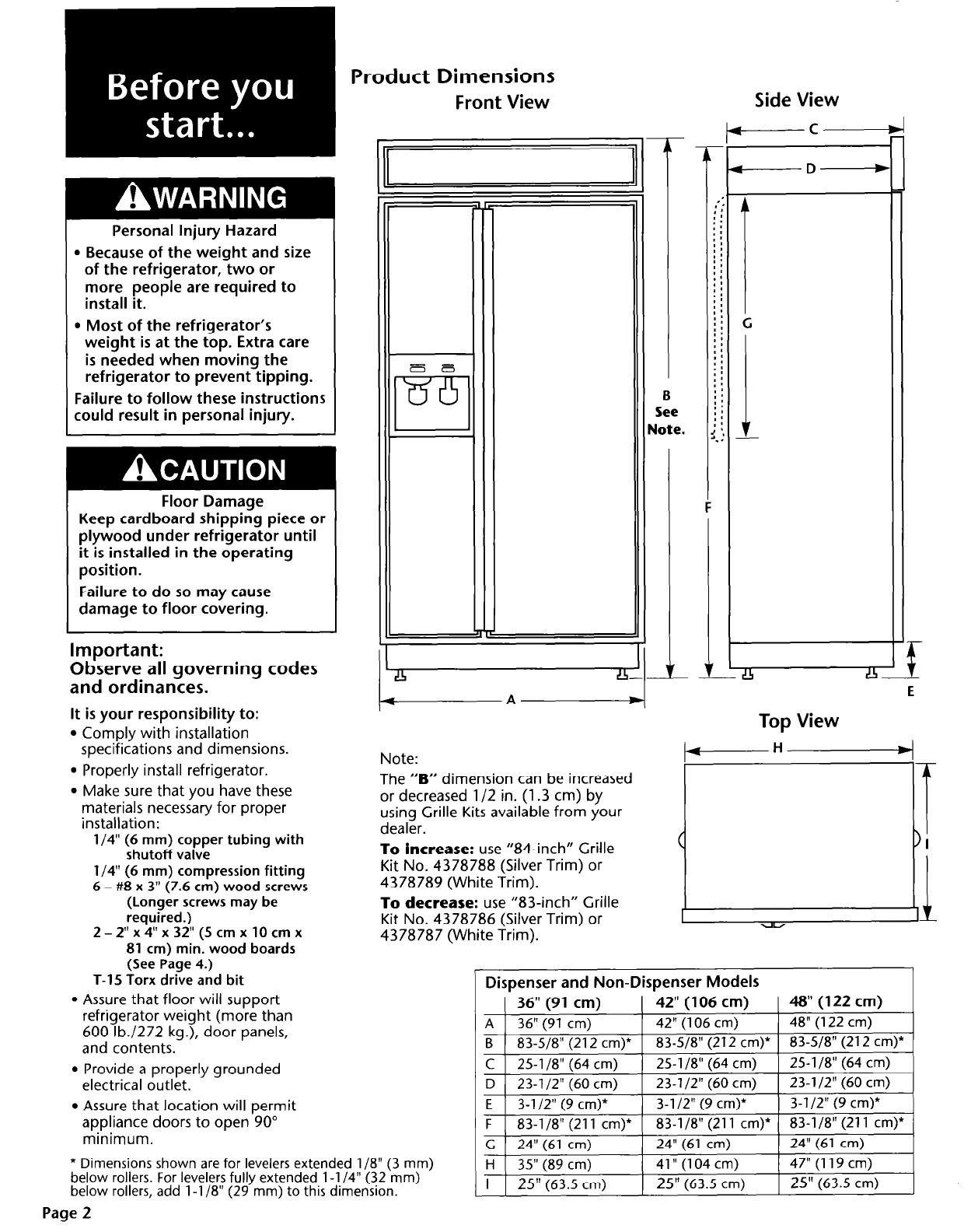
Product Dimensions
Front View
Personal Injury Hazard
. Because of the weight and size
of the refrigerator, two or
more people are required to
install it.
l Most of the refrigerator’s
weight is at the top. Extra care
is needed when moving the
refrigerator to prevent tipping.
Failure to follow these instructions
could result in personal injury.
Floor Damage
Keep cardboard shipping piece or
plywood under refrigerator until
it is installed in the operating
position.
Failure to do so may cause
damage to floor covering.
Important:
Observe all governing codes
and ordinances.
It is your responsibility to:
l
Comply with installation
specifications and dimensions.
l
Properly install refrigerator.
l
Make sure that you have these
materials necessary for proper
installation:
l/4” (6 mm) copper tubing
with
shutoff valve
l/4” (6 mm) compression fitting
6 - #8 x 3" (7.6
cm) wood screws
(Longer screws may be
required.)
2 - 2" x 4" x 32"
(5 cm x 10 cm x
81 cm) min. wood boards
(See Page 4.)
T-15 Torx drive and bit
l
Assure that floor will support
refrigerator weight (more than
600 lb./272 kg.), door panels,
and contents.
l
Provide a properly grounded
electrical outlet.
!I4
-
A-
Note:
The “B” dimension can be increased
or decreased l/2 in. (1.3 cm) by
using Grille Kits available from your
dealer.
To increase:
use “84-inch” Grille
Kit No. 4378788 (Silver Trim) or
4378789 (White Trim).
To decrease:
use “83-inch” Grille
Kit No. 4378786 (Silver Trim) or
4378787 (White Trim).
-
B
See
Jote.
Side View
t------C
-D-
‘f
- LFhL
E
Top View
Dispenser and Non-Dispenser Models
( 36" (91 cm)
1 42"(106 cm)
1 48” (122 cm)
A 1 36” (91 cm)
1 42" (106 cm)
1 48" (122 cm)
I
I
I
B ) 83-518" (212 cm)* 1 83-518” (212 cm)* 1 83-518” (212 cm)*
1
C
25-1/8"(64 cm)
25-l /8” (64 cm)
25-l /8” (64 cm)
D 23-1/2"(60 cm)
23-1/2"(60 cm)
23-1/2"(60 cm)
E 3-l/2" (9 cm)*
3-l /2” (9 cm)*
3-l/2" (9 cm)*
I
\ ,
I
. ,
I
F 1 83-118" (211 cm)* [ 83-118” (211 cm)* ( 83-l/8” (211 cm)*
c 24"(61 cm)
24" (61 cm)
24" (61 cm)
H 35"(89 cm)
41” (104 cm)
47" (119 cm)
I
25"
(63.5 cm)
25"
(63.5 cm)
25" (63.5
cm)
l
Assure that location will permit
appliance doors to open 90”
minimum.
* Dimensions shown are for levelers extended l/B” (3 mm)
below rollers. For levelers fully extended l-l /4” (32 mm)
below rollers, add l-l /8” (29 mm) to this dimension.
Page 2
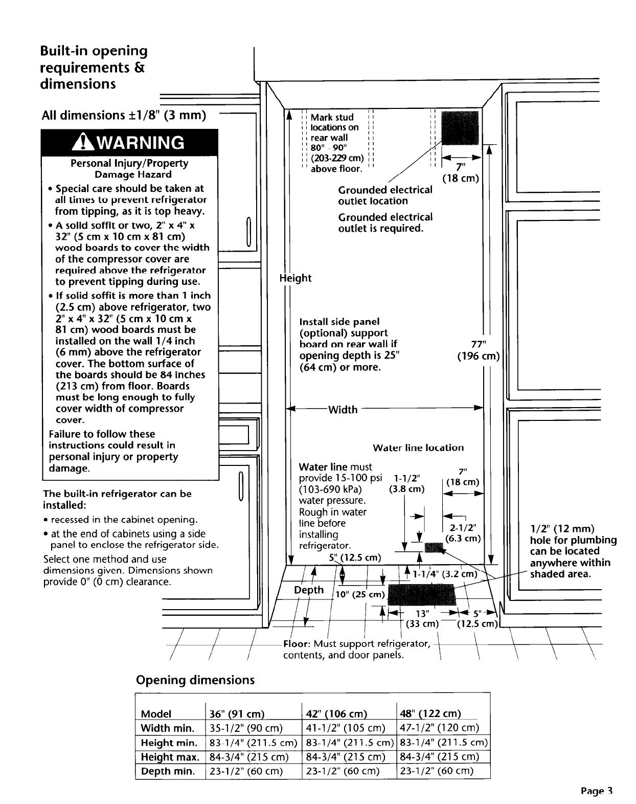
Built-in opening
requirements &
dimensions
All dimensions +1/8” (3 mm)
-
Personal Injury/Property
Damage Hazard
l Special care should be taken at
all times to prevent refrigerator
from tipping, as it is top heavy.
l A solid soffit or two, 2” x 4” x
32”
(5 cm x 10 cm x 81 cm)
wood boards to cover the width
of the compressor cover are
required above the refrigerator
to prevent tipping during use.
l If solid soffit is more than 1 inch
(2.5 cm) above refrigerator, two
2” x 4” x 32”
(5 cm x 10 cm x
81 cm) wood boards must be
installed on the wall l/4 inch
(6 mm) above the refrigerator
cover. The bottom surface of
the boards should be 84 inches
(213 cm) from floor. Boards
must be long enough to fully
cover width of compressor
cover.
Failure to follow these
instructions could result in
personal injury or property
damage.
The built-in refrigerator can be
installed:
l
recessed in the cabinet opening.
l
at the end of cabinets using a side
panel to enclose the refrigerator side.
Select one method and use
dimensions given. Dimensions shown
provide 0” (0 cm) clearance.
II
II
I
I I (203229
cm) I I
’ ’ above floor. ’ ’
Grounded electrical
outlet location
Grounded electrical
outlet is required.
Install side panel
(optional) support
board on rear wall if
opening depth is 25”
(1 !ZZm)
(64
cm) or more.
-Width
*
Water line location
Water line
must
provide 15-l 00 psi l-1/2”
(103-690 kPa)
(3.8 cm) V
water pressure.
I
I I
, / 11 I
I T
I I
1 (33 cm) -(12.5 cm)
l/2” (12 mm)
hole for plumbing
can be located
anywhere within
- shaded area.
Floor:
Must support refrigerator, l
\
\ \
\
contents, and door panels.
Opening dimensions
Model
36” (91
cm)
42” (106
cm)
48” (122 cm)
Width min.
35-l/2” (90 cm)
41-l /2” (105 cm)
47-l /2” (120 cm)
Height min.
83-l /4” (211.5 cm) 83-l /4” (211.5 cm) 83-l /4” (211.5 cm)
Height max. 84-3/4” (215 cm)
84-3/4” (215 cm)
84-3/4” (215 cm)
Depth min. 23-l /2” (60
cm)
23-l /2” (60 cm)
23-l /2” (60 cm)
Page 3
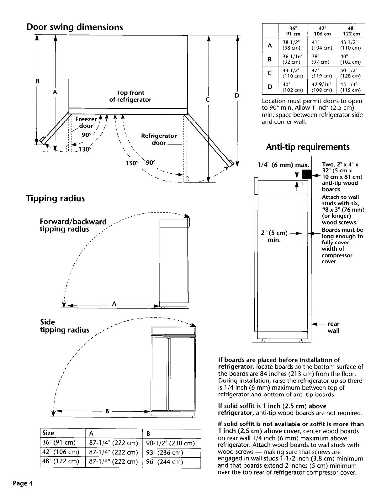
Door swing dimensions
1
B
A
Top front
of refrigerator
Tipping radius
Forward/backward _x-xT-*--
tipping radius ,,1-’
,’
#’
I’
I
I
I
r’
I
I’
I’
_____-------____
tipping radius ,/l’-
/
/
/
/
/
/
/
Side
__--
_------_
*’
e3l
/
/I
/
I
I
V-B-
87-l /4” (222 cm)
90-l /2” (230 cm)
Location must permit doors to open
to 90” min. Allow 1 inch (2.5 cm)
min. space between refrigerator side
and corner wall.
Anti-tip requirements
l/4” (6 mm) ma,
2” (5 cm)
min.
Two 2” x 4” x
32” (5 cm x
*lOcmx81 cm)
anti-tip wood
boards
Attach to wall
studs with six,
#8 x 3” (76 mm)
(or longer)
wood screws.
Boards must be
- long enough to
fully cover
width of
compressor
cover.
+ rear
wall
I
44
I
If boards are placed before installation of
refrigerator,
locate boards so the bottom surface of
the boards are 84 inches (213 cm) from the floor.
During installation, raise the refrigerator up so there
is l/4 inch (6 mm) maximum between top of
refrigerator and bottom of anti-tip boards.
If solid soffit is 1 inch (2.5 cm) above
refrigerator,
anti-tip wood boards are not required.
If solid soffit is not available or soffit is more than
1 inch
(2.5 cm)
above cover,
center wood boards
on rear wall l/4 inch (6 mm) maximum above
refrigerator. Attach wood boards to wall studs with
wood screws - making sure that screws are
engaged in wall studs l-l /2 inch (3.8 cm) minimum
and that boards extend 2 inches (5 cm) minimum
over the top rear of refrigerator compressor cover.
Page 4
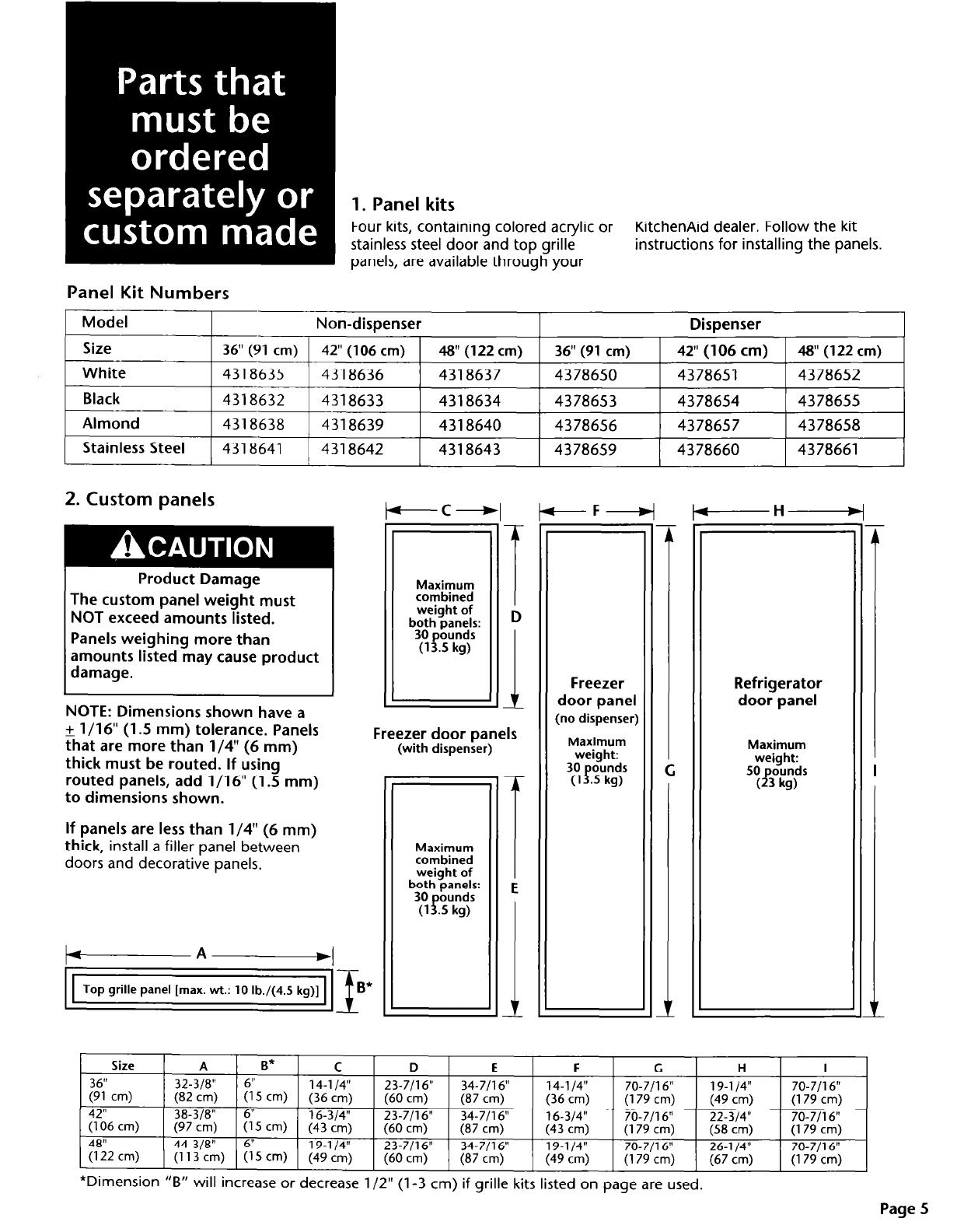
1. Panel kits
Four kits, containing colored acrylic or
KitchenAid dealer. Follow the kit
stainless steel door and top grille
instructions for installing the panels.
panels, are available through your
Panel Kit Numbers
Model
Non-dispenser
Dispenser
Size
36"
(91 cm)
42" (106
cm)
#I"(122
cm)
36"(91
cm)
42"
(106 cm)
W(122
cm)
White
4318635
4318636
4318637
4378650
4378651
4378652
Black
4318632
4318633
4318634
4378653
4378654
4378655
Almond
4318638
4318639
4318640
4378656
4378657
4378658
Stainless
Steel
4318641
4318642
4318643
4378659
4378660
4378661
2. Custom panels
Product Damage
The custom panel weight must
NOT exceed amounts listed.
Panels weighing more than
amounts listed may cause product
damage.
NOTE: Dimensions shown have a
+ l/16” (1.5 mm) tolerance. Panels
that are more than l/4” (6 mm)
thick must be routed. If using
routed panels, add l/16” (1.5 mm)
to dimensions shown.
If panels are less than l/4” (6 mm)
thick,
install a filler panel between
doors and decorative panels.
-C+
-A
+
Top grille panel [max. wt.:
10 lb./(4.5 kg)]
Freezer door panels
(with dispenser)
Maximum
combined
weight of
both panels:
30
ounds
(1 p.5 kg)
Size
36"
(gl cm)
A
B*
C
D
32-318"
6"
14-l/4"
I^_ \ I- r \ ._ _
E F G
H
I
23-7/16"
34-7/16" 14-l/4" 70-7/16"
19-l 14”
70-7/16"
(t5.i cm)
(13 cm)
(36
cm)
(60
cm)
(87 cm) (36
cm) (179 cm)
(179 cm)
’
42"
(49 cm)
38-318"
23-7/l 6”
(106
cm)
34-7/l 6”
16-314”
(97 cm)
(6;‘5 cm) :&‘c$
70-7/l 6”
22-314"
70-7116"
(60
cm)
(87
cm)
(43
cm) (179 cm)
(58
cm)
(179 cm)
48"
44-3/8"
6"
19-l 14”
23-7/l 6”
(122 cm)
(113 cm) (15
cm)
(49 cm)
34-7/l 6”
19-l 14”
70-7Jl6"
26-l/4"
70-7116"
(60
cm)
(87
cm) (49 cm) (179 cm)
(67
cm)
(179 cm)
L
r
Freezer
door panel
(no dispenser)
Maximum
weight:
30 ounds
(1 f.5 kg)
-H
Refrigerator
door panel
Maximum
weight:
50 ounds
33
kg)
*Dimension “B” will increase or decrease l/2” (l-3 cm) if grille kits listed on page are used.

End view of handle side of panel
Custom panels
3- l/4”
Dimensions for
more than l/4”
(6 mm) thick:
routing panel
Route entire length
edges
or selected areas of
handle side of
panels 3-l /4”
(8.25
cm).
l/4” (6mm )max.
(
Side view
-7
nanare
min.
panel
L’ L’
314” 314”
f f
19 mm) 19 mm)
min. min.
panel panel
f f
+ l/4”
(6 mm) max.
3. Side panels
If side panel will be installed inside
side trim and the side panel is more
than l/4” (6 mm) thick,
route front
edge of panel to fit trim piece.
End view of side trim piece
1/4”-D
(6 mm)
l/16”
(1.5 mm)
7132”
(5.5 mm)
$
i
+
--I+
+ s/32”
I I
(4 mm>
13/32” (10 mm)
side panel inside side panel outside
side trim piece. side trim piece.
Width and height:
depend on
installation type.
Thickness:
l/2” (12 mm)
minimum to
prevent warping.
Notches for toe
panel recess
(if desired). \
Determine
installation height
before cutting
notches.
support
board
side panel outside side
trim piece and recessed.
side panel
su~~ort nailer
side trim piece
Page 6
Electrical Requirements
Electrical Shock Hazard
b Electrical ground is required on
this appliance.
B If cold water pipe is interrupted
by plastic, non-metallic gaskets
or other insulating materials, Do
Not use for grounding.
b Do Not ground to gas pipe.
l Do Not modify the power supply
cord plug. If it does not fit the
outlet, have a proper outlet
installed by a qualified
electrician.
m Do Not have a fuse in the neutral
or grounding circuit. A fuse in
the neutral or grounding circuit
could result in an electrical shock.
m Do Not use an extension cord
with this appliance.
l Check with a qualified electrician
if you are in doubt as to whether
the appliance is properly
grounded.
It is the customer’s responsibility:
l To contact a qualified electrical
installer.
. To assure that the electrical
installation is adequate and in
conformance with the National
Electrical Code, ANWNFPA 70 -
latest edition** or Canadian
Electrical Code, C22.1-1982 and
C22.2 No. 01982 (or latest
edition)*, and all local codes and
ordinances.
Failure to follow these instructions
could result in death or serious
injury.
If codes permit and a separate
grounding wire is used, it is
recommended that a qualified
electrician determine that the
grounding path is adequate.
A 120-volt, 60-Hz, AC-only, 15 or 20-
ampere, fused, electrical supply is
required. A time-delay fuse or circuit
breaker is recommended. It is
recommended that a separate circuit
serving only this appliance be provided.
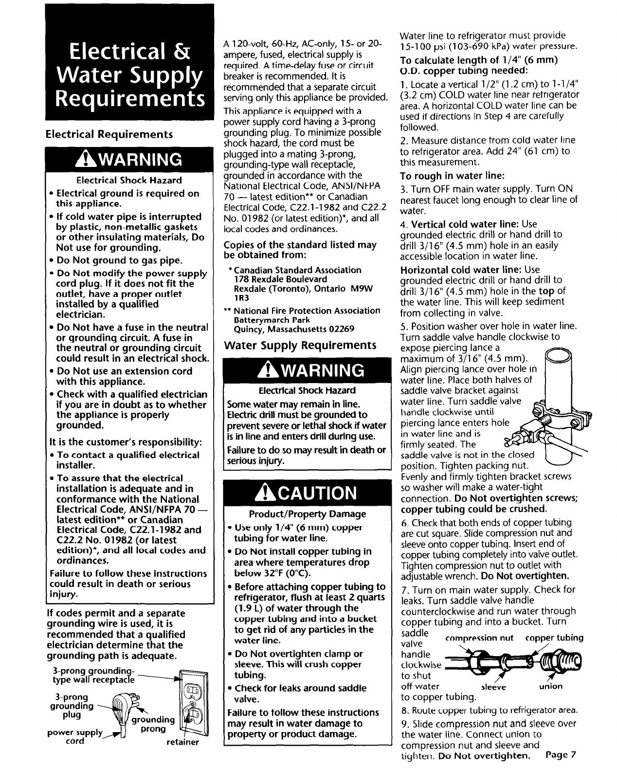
This appliance is equipped with a
power supply cord having a 3-prong
grounding plug. To minimize possible
shock hazard, the cord must be
plugged into a mating 3-prong,
grounding-type wall receptacle,
grounded in accordance with the
National Electrical Code, ANSVNFPA
70 -
latest edition** or Canadian
Electrical Code, C22.1-1982 and C22.2
No. 01982 (or latest edition)*, and all
local codes and ordinances.
Copies of the standard listed may
be obtained from:
*Canadian Standard Association
178 Rexdale Boulevard
Rexdale (Toronto), Ontario M9W
lR3
** National Fire Protection Association
Batterymarch Park
Quincy, Massachusetts 02269
Water Supply Requirements
I
Electrical Shock Hazard
I
Some water may remain in line.
Electric drill must be grounded to
prevent severe or lethal shock if water
is in line and enters drill during use.
Failure to do so may result in death or
serious injury.
Product/Property Damage
l Use only l/4” (6 mm) copper
tubing for water line.
. Do Not install copper tubing in
area where temperatures drop
below 32°F (0°C).
l Before attaching copper tubing to
refrigerator, flush at least 2 quarts
(1.9 L) of water through the
copper tubing and into a bucket
to get rid of any particles in the
water line.
. Do Not over-tighten clamp or
sleeve. This will crush copper
tubing.
l Check for leaks around saddle
valve.
Failure to follow these instructions
may result in water damage to
property or product damage.
Water line to refrigerator must provide
15-l 00 psi (103-690 kPa) water pressure.
To calculate length of l/4” (6 mm)
O.D. copper tubing needed:
1. Locate a vertical l/2” (1.2 cm) to l-l /4”
(3.2 cm) COLD water line near refrigerator
area. A horizontal COLD water line can be
used if directions in Step 4 are carefully
followed.
2. Measure distance from cold water line
to refrigerator area. Add 24” (61 cm) to
this measurement.
To rough in water line:
3. Turn OFF main water supply. Turn ON
nearest faucet long enough to clear line of
water.
4. Vertical cold water line:
Use
grounded electric drill or hand drill to
drill 3/l 6” (4.5 mm) hole in an easily
accessible location in water line.
Horizontal cold water line:
Use
grounded electric drill or hand drill to
drill 3/l 6” (4.5 mm) hole in the
top
of
the water line. This will keep sediment
from collecting in valve.
5. Position washer over hole in water line.
Turn saddle valve handle clockwise to
expose piercing lance a
maximum of 3/l 6” (4.5 mm).
Align piercing lance over hole in
water line. Place both halves of
saddle valve bracket against
water line. Turn saddle valve
handle clockwise until
piercing lance enters hol
in water line and is
firmly seated. The
saddle valve is not in th
position. Tighten
packing nut.
Evenly and firmly tighten bracket screws
so washer will make a water-tight
connection.
Do Not over-tighten screws;
copper tubing could be crushed.
6. Check that both ends of copper tubing
are cut square. Slide compression nut and
sleeve onto copper tubing. Inset-t end of
copper tubing completely into valve outlet.
Tighten compression nut to outlet with
adjustable wrench.
Do Not overtighten.
7. Turn on main water supply. Check for
leaks. Turn saddle valve handle
counterclockwise and run water through
copper tubing and into a bucket. Turn
saddle
valve
compression nut
copper tubing
/
.-. -
handle
clockwise
to shut
off water
sleeve
u&on
to copper tubing.
8. Route copper tubing to refrigerator area.
9. Slide compression nut and sleeve over
the water line. Connect union to
compression nut and sleeve and
tighten.
Do Not over-tighten.
Page 7

Parts supplied for ins:allation:
l
base grille
l
miscellaneous parts bag
Check l-hat all
part, were nc ludetl
Product/Property Damage
l
Do Not lower the refrigerator
against the shipping base when
removing the shipping base.
l
Do Not remove protective film
until refrigerator is in operating
position.
l
All four leveling legs must
contact the floor to support and
stabilize the full weight of the
refrigerator.
l
Keep cardboard shipping piece
or plywood under refrigerator
until it is installed in operating
position.
Failure to follow these instructions
may cause damage to product olr
floor covering.
1
Remove and save literature
. package and parts bag taped to
refrigerator door. Remove four
brackets (two on each side) attaching
shipping base to refrigerator bottorn.
Do Not remove tape and door
bracing until product is secured in
final location. See Page 3.
Personal Injury Hazard
l
Because of the weight and size of
the refrigerator, two or more
people are required to install it.
l
Most of the refrigerator’s weight
is at the top. Extra care is needed
when moving the refrigerator
to
prevent tipping.
Failure to follow these instructions
could result in personal injury.
3
Place sections of shipping carton
. on the floor when rolling dolly
and refrigerator into the house. Move
refrigerator close to built-in opening.
4
Set*power switc
at top of cabinet
to “OFF” position.
Plug power supply
cord into
grounded outlet.
Install retainer on
grounded outlet using
screw from parts bag.
5
Place top of cardboard
. carton or plywood under
refrigerator. Remove dolly. Open
appliance doors and remove all boxes,
parts packages and packing materials
from refrigerator and freezer
compartments. Do Not remove
protective film.
Move the refrigerator straight back and
evenly into the opening. Check that:
l
copper tubing is not kinked.
l
power supply cord is on top of
refrigerator next to cover.
corner of
I
\
\
Ye
I
l/4” (6 mm)
(6
mm)
compression
union
nut
I I
l/4” (6 mm)
compression
nut
l/4”
(6
mm)
sleeve
Slide a compression nut and sleeve on
open end of each copper line. Use a
copper tubing union to connect both
copper lines.
Do Not overtighten.
Turn water supply valve to “OPEN”
position. Turn refrigerator switch
“ON.” Wait a few minutes. Check
water line connection and water valve
on top of cabinet for leaks. Without
kinking the tubing, carefully place it
back underneath cabinet.
Insert carton corner posts between
strap and refrigerator at side trim
Check that water supply line has
pieces and handles. Carefully tighten
been flushed. See Page 7.
strap making sure side trim and
6
Pull copper line from refrigerator
handles are protected.
.
water valve and copper line from
plumbing forward from underneath
Paae 8
refrigerator. Remove cap from water line.

Filler panel
re uired if -
pane s are less
7
than l/4”
(6 mm) thick.
nylon
/
washers
(discard)
door
handle-
IGcorative
9
panel
. Remove all taDe and door bracinq
If panels are
more than
l/4” (6 mm)
thick, route
panel edges
on all sides.
from refrigerator and freezer doors.
Remove screws attaching handles to
door frames. Discard nylon washers
underneath screws. Slide decorative
door panels into door frames.
If panels are less than l/4” (6 mm)
thick,
install a filler panel between
door and decorative panel.
If panels are more than l/4” (6 mm)
thick,
route panel edges on all sides.
are atigned and teveJ,
lf4~~~s iwsd ta be adjusted
kbr fight or bl or out,
bmen’&e 3/S” (9 mm) hex
hwfid screws in the tap hinge5
# dptws md to be adjusted
up or
down,
loosen the 3/8
(9 rnmi~ hex head screws in
the b&torn hinges.
Adju$t doors. Tighten screws.
ftimk that doors are aligned
and levei.
assembiy
Remove door stop set screw
located in top and bottcvn
hinges using a f-7 4 Tom
wrench.
Hotd door in the desired position
and replrace ~?t crews. I# door
does not clear countertop after
door stop has been adjusted,
countertops may need to be
““mitered.
top grille
14 .
Slide top grille decorative panel
assembly up and off top grille
assembly. Release the two tethers
holding the decorative panel to the
top grille assembly.
Page 9
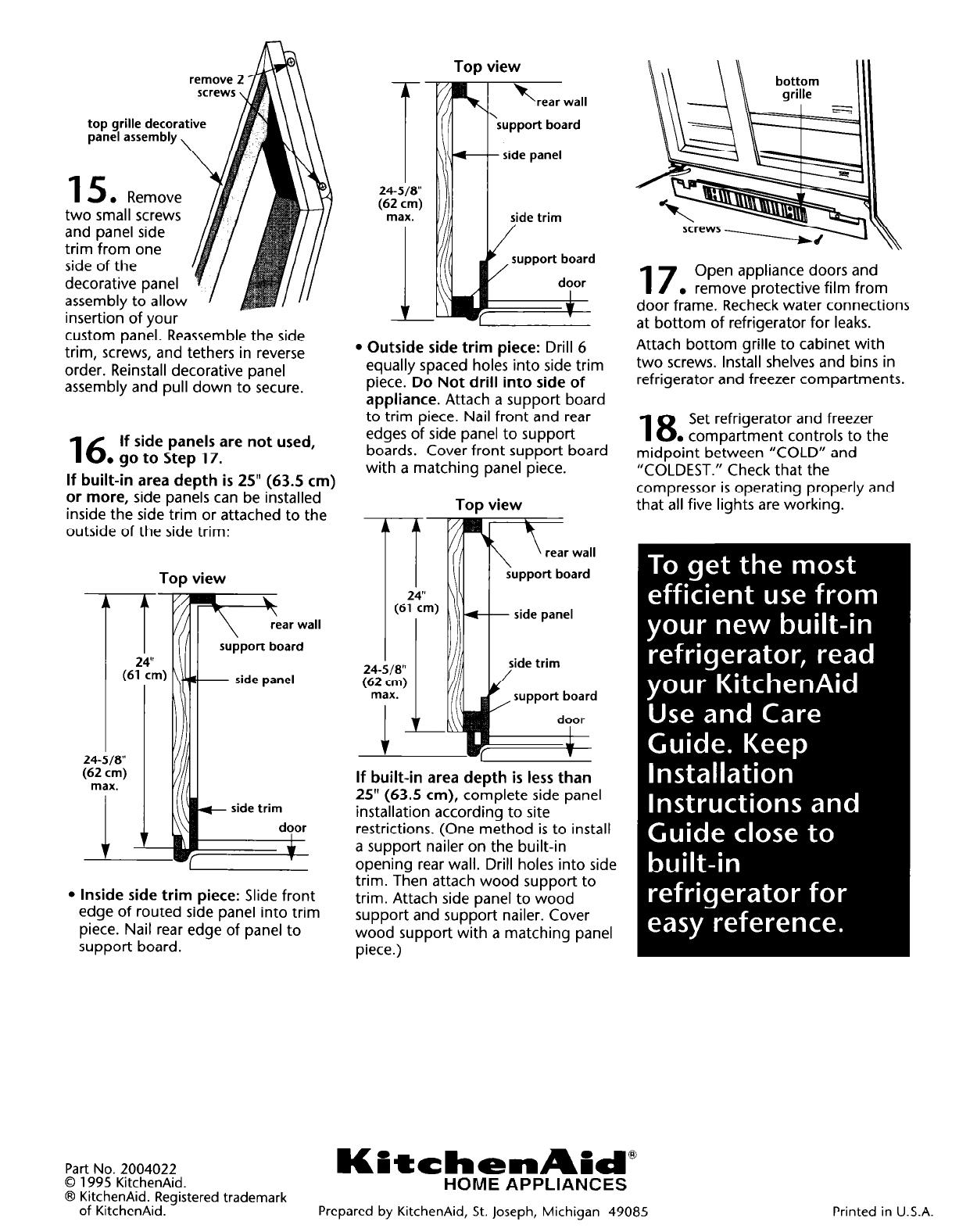
top grille decorative
panel assembly,
two small screws
and panel side
trim from one
side of the
decorative panel
assembly to allow
insertion of your
---
custom panel. Reassemble the side
trim, screws, and tethers in reverse
order. Reinstall decorative panel
assembly and pull down to secure.
16
If side panels are not used,
. go to Step 17.
If built-in area depth is 25” (63.5 cm)
or more,
side panels can be installed
inside the side trim or attached to the
outside of the side trim:
-
I
24-518”
(62 ;m)
max.
Top view
l Inside side trim piece:
Slide front
edge of routed side panel into trim
piece. Nail rear edge of panel to
support board.
Top view
24-518”
(62 cm)
max.
L
l Outside side trim piece:
Drill 6
equally spaced holes into side trim
piece.
Do Not drill into side of
appliance.
Attach a support board
to trim piece. Nail front and rear
edges of side panel to support
boards. Cover front support board
with a matching panel piece.
Top view
24-
\
\ rear wall
support board
- side panel
side trim
door
If built-in area depth is less than
25” (63.5
cm),
complete side panel
installation according to site
restrictions. (One method is to install
a support nailer on the built-in
opening rear wall. Drill holes into side
trim. Then attach wood support to
trim. Attach side panel to wood
support and support nailer. Cover
wood support with a matching panel
piece.)
17
Open appliance doors and
. remove protective film from
door frame. Recheck water connections
at bottom of refrigerator for leaks.
Attach bottom grille to cabinet with
two screws. Install shelves and bins in
refrigerator and freezer compartments.
18
Set refrigerator and freezer
. compartment controls to the
midpoint between “COLD” and
“COLDEST.” Check that the
compressor is operating properly and
that all five lights are working.
Part No. 2004022
KPtchenAid”
0 1995 KitchenAid.
8 KitchenAid. Registered trademark
HOME APPLIANCES
of KitchenAid.
Prepared by KitchenAid, St. Joseph, Michigan 49085
Printed in U.S.A.
/