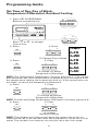
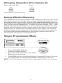
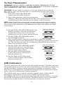
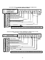
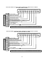
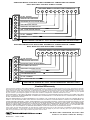
Aprilaire 8355 is a 7-day programmable thermostat with 2 heat/2 cool settings for heat pump systems. It features four pre-programmed setpoints for each day of the week, fast and easy programming, energy-efficient recovery, residual cooling, and a low battery indicator. The large display shows the time of day and temperature, and the multi-colored LED indicators provide system status. The thermostat is compatible with 100% lockout systems and can be reset by turning it to the OFF position for at least 60 seconds.
Aprilaire 8355 is a 7-day programmable thermostat with 2 heat/2 cool settings for heat pump systems. It features four pre-programmed setpoints for each day of the week, fast and easy programming, energy-efficient recovery, residual cooling, and a low battery indicator. The large display shows the time of day and temperature, and the multi-colored LED indicators provide system status. The thermostat is compatible with 100% lockout systems and can be reset by turning it to the OFF position for at least 60 seconds.


-
 1
1
-
 2
2
-
 3
3
-
 4
4
-
 5
5
-
 6
6
-
 7
7
-
 8
8
-
 9
9
-
 10
10
-
 11
11
-
 12
12
-
 13
13
-
 14
14
-
 15
15
-
 16
16


Aprilaire 8355 is a 7-day programmable thermostat with 2 heat/2 cool settings for heat pump systems. It features four pre-programmed setpoints for each day of the week, fast and easy programming, energy-efficient recovery, residual cooling, and a low battery indicator. The large display shows the time of day and temperature, and the multi-colored LED indicators provide system status. The thermostat is compatible with 100% lockout systems and can be reset by turning it to the OFF position for at least 60 seconds.
Ask a question and I''ll find the answer in the document
Finding information in a document is now easier with AI
Related papers
-
Aprilaire 8336 User manual
-
-
-
-
-
-
-
-
-
Other documents
-
ICM Controls SC2201 Installation, Operation & Application Manual
-
GE RAK149P2 Digital Programmable Wall Thermostat Owner's manual
-
Lux Products TX500U Owner's manual
-
-
protech PRO-615 Installation Instructions And Owner's Manual
-
Braeburn 2000NC User manual
-
Lux LTX9600TS-A04 User manual
-
Bryant 5200 User manual
-
-