Page is loading ...

Water heater
INSTRUCTION & INSTALLATION GUIDE
Capri

2

3
Water heater
Capri
Content
1.
Important rules............................................................................................................................................................................4
2.
Installation and connecting......................................................................................................................................................5
3.
Hydraulic installation.................................................................................................................................................................7
4.
Electric installation................................................................................................................................................................8
5.
Safety precautions.....................................................................................................................................................................9
6.
Use (Putting into operation)....................................................................................................................................................9
7.
Maintenance ...........................................................................................................................................................................11
8.
Rointe Product Guarantee.......................................................................................................................................................11
9.
European Directive....................................................................................................................................................................13
10.
Dimensions & Technical Characteristics...............................................................................................................................13
11.
Certicate of Guarantee...........................................................................................................................................................15
IMPORTANT
Please read this Instruction Manual carefully to ensure correct operation. It is important that the
installer reads and understands these instructions and unpacks and familiarises themselves with
the equipment before commencing the installation. Please leave this manual with the product after
installation. Failure to observe these installation instructions could render the guarantee null and
void.
ATTENTION
Thank you very much for choosing the CAPRI water heater model, made with the highest quality
components designed for you.
The CAPRI water heaters have passed the most stringent quality controls to meet the most stringent
safety requirements. Before starting to use the CAPRI water heaters, the manual recommended with
this manual, in order to obtain the correct operation with the maximum guarantees.

4
1. IMPORTANT RULES
Attention! Improper installation and connection of the appliance may make it hazardous for the health and
life of consumers. It may cause grievous and permanent consequences, including but not limited to physical
injuries and/or death. Improper installation and connection of the appliance may also lead to damage to the
consumers’ property /damage and/ or destruction/, or to that of third persons, as a result of, but not limited
to ooding, explosion and/or re.
Installation, connection to the main water and power supply, and putting into operation must be carried out
by certied electricians and technical personnel certied in installation of this category of appliances, who
have obtained their license in the state where the installation and commissioning of the appliance are carried
out, and in compliance with its local legislation.
• The water heater is to be installed only on premises with standard re safety.
• Do not switch on the appliance before making sure it is full of water.
• Make sure the supply voltage meets the value indicated on the appliance. Make sure the pressure of the
water system does not exceed 6 Bar (0.6 MPa).
• The appliance has to be installed on premises where there is no danger of freezing.
• Avoid turning on other electrical appliances with similar power when using the water heater.
• If you are not to use the appliance for a long time turn o the power supply to it and shut the control cock
well.
• The open type water heaters (with given pressure of 0 Pa – see nameplate of the appliance)it is not allowed
to shut the hot water outlet via stop cock or other types of isolating ttings. It has to always be open to the
atmosphere.
• If the supply cord (for the models tted with such) is damaged, it has to be replaced by a service oce
representative or a person of similar qualication in order to avoid any risks.
• Do not use the appliance for purposes other than the ones described in this instruction.
• Do not dismantle the front panel before turning o power supply to the heater.
• In case of fault turn o the power supply of the appliance immediately
• Only the authorized service oces listed in the warranty card are entitled to performing the service
maintenance of the product and to selling spare parts for the appliance.
• The appliance has a lter at the inlet. The lter protects it from solid particles which can cause fault. Clean
the lter periodically
• The shower head included in the set for the bathroom models is tted with a cleaning system. Regularly
clean the shower head to achieve correct and trouble-free operation of the appliance.
• This appliance can be used by children aged from 8 years and above and persons with reduced physical,
sensory or mental capabilities or lack of experience and knowledge if they have been given supervision or
instruction concerning use of the appliance in a safe way and understand the hazards involved.
• Children shall not play with the appliance.
• Cleaning and user maintenance shall not be made by children without supervision.

5
2. INSTALLATION AND CONNECTING
Attention! Improper installation and connection of the appliance may make it hazardous for the health and
life of consumers. It may cause grievous and permanent consequences, including but not limited to physical
injuries and/or death. Improper installation and connection of the appliance may also lead to damage to the
consumers’ property /damage and/ or destruction/, or to that of third persons, as a result of, but not limited
to ooding, explosion and/or re.
2.1. Installation. The appliance shall be installed in premises where the temperature does not fall below 4°С
and there is no danger for the water to freeze.
The appliances have been hydraulically tested during manufacture. A little water may leak from the ingoing
and the leading-out pipes of the appliance when the protection caps are removed.
2.2. Models designed for the kitchen (supplied with a mixing tap). It is not allowed to use connecting
ttings that are not from the manufacturer or have not been agreed upon with them. The following order
shall be adhered to during installation:
· The mixing tap is installed to the water supply system so that the handles are positioned horizontally – g.1
· For the cordless models – the supply conductors have to be connected to the appliance beforehand. It is
necessary to follow the instructions in item 3.3 of Section VI: Connecting to the electricity grid.
· The appliance is installed directly to the mixing tap (1) by using the 2 nuts with gaskets (2) – g. 1. Unscrew
the nuts up to two or three turns. Place the pipes of the appliance in the nuts openings and press slightly until
stop piece. Screw the nuts rmly in order to tighten the connection.
· Install thespout.
· The appliance has to be lled with water. The supply voltage has to be switched o. Turn the red-colour
handle to let water run to the heater. Wait until a continuous water jet starts running from the spout.
· Once the appliance is full of water, you can switch on the supply voltage.
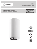
2.3. Models for the bathroom
The following order shall be adhered to during installation:
· Select the position for the shower head holder by taking into account the height - “h” g.2 desired by you
for the position of the shower.
Fig.1

6
· Place the holder onto the wall and mark the holes for attaching
· Drill holes and install the xing plugs in them. Place the holder, tighten the screws then place the ornamental
caps on top of the screws
· Select position for the appliance – the appliance has to be installed in an area where it will not be directly
splashed with water. It is xedly installed to a plastic holder (included in the
set) which is xed to wall beforehand.
· Place the holder (hook) for the appliance onto the wall and mark the holes for xing (g. 3)
· Drill holes and install the xing plugs in them then place the holder and tighten the screws (g. 3)
· Attach the appliance to the holder - (g.4) by taking into account the following:
· for the cordless models with a plug - the supply conductors have to be connected to the appliance
beforehand. It is necessary to follow the instructions in item 3.3 of Section VI: Connecting to the electricity
grid.
· if you want the tap to be directly connected to the appliance, you have to install it beforehand.
Fig.3
Fig.4
Fig.2

7
2.4. IN LINE models
The incoming and the leading-out pipes of the appliance have R1/2” fastening thread.The inlet and the outlet
are indicated by arrows on the back lid of the appliance (or on the tubes themselves). The arrows show the
direction of the water ow. These models are designed as a closed type(pressurized). The cock for running,
control and stopping of the water ow is installed after the appliance.
It is not allowed to install any back valves and closed isolating ttings in the water system before the appliance.
The appliance can be connected to more than one hot water point of use.
The water heater cannot supply enough hot water in cases of simultaneous consumption from two points
ofuse!
After connecting the appliance and before switching the power on, open the hot water tap until a steady
water jet starts running!
3. HYDRAULIC INSTALLATION
3.1. Connection of the water heater to the water supply system (g.2). The appliance has to be connected
to the water system for supply of cold water with a pressure not lower than 1.5 bar (0.15 MPa) and not higher
than 6 bar (0.6 MPa).
If the pressure in the water supply system is over 0.6MPa (6 bars), PRESSURE REDUCING VALVE has to be installed
in the water supply system before the appliance. The pressure reducing valve is not included in the set of the
appliance!
It is not allowed to use the appliance in systems with preliminarily heated water. The highest allowed
temperature at the inlet of the appliance is 20°С.
The resistance of water cannot be lower than the value given on the nameplate of the appliance.
3.2. Models for the kitchen – g. 1. It is not allowed to use connecting ttings that are not from the
manufacturer or have not been agreed
upon with them.
The thread at the inlet of the mixing tap (included in the set) is ½”. The tap is directly connected to the water
supply system and the appliance is installed to it- see item 1.1 above.
After connecting the appliance and before switching on the power, open the hot water tap until a constant
water jet starts running!
3.3. Models for the bathroom – g. 2
The incoming and the leading-out pipes of the appliance have R1/2” fastening thread.The inlet and the outlet
are indicated by arrows on the back lid of the appliance (or on the tubes themselves). The arrows show the
direction of the water ow.
The cock for running, control and stopping of the water ow is connected to the inlet of the appliance. It can
be installed directly on the incoming pipe of the water heater or at a distance via a exible hose (not included
in the set) when necessary.
The exible hose of the shower head is directly connected to the outlet of the appliance.
IMPORTANT! These models are open type (with nominal pressure of 0 Pa). It is not allowed to shut the hot water
outlet via a stop cock or other types of isolating ttings! It
has to always be open to the atmosphere (these models contact the atmosphere via the shower head and

8
the exible hose)!
After connecting the appliance and before turning on the electric supply, open the tap until steady jet of water
starts running from the shower head!
3.4. IN Line models – g. 5
The incoming and the leading-out pipes of the appliance have R1/2” fastening thread.The inlet and the outlet
are indicated by arrows on the back lid of the appliance (or on the tubes themselves). The arrows show the
direction of the water ow. These models are designed as a closed type(pressurized). The cock for running,
control and stopping of the water ow is installed after the appliance.
It is not allowed to install any back valves and closed isolating ttings in the water system before the appliance.
The appliance can be connected to more than one hot water point of use.
The water heater cannot supply enough hot water in cases of simultaneous consumption from two points ofuse!
After connecting the appliance and before switching the power on, open the hot water tap until a steady
water jet starts running!
4. ELECTRIC INSTALLATION
4.1. Connection to the electricity grid
The appliance has to be earthed! Do not switch on the power of the appliance before making sure that it is
full of water!
4.2. Water heater tted with supply cord and a plug
· The plug has to be plugged in to a properly connected and earthed socket.
· The socket has to be connected to a separate electrical circuit supplied with a safety fuse. The section of the
supply conductors and the nominal power of the safety fuse have to conform with the data given in Table 1
· The verication of the fulllment of the abovementioned requirements shall be carried out by a qualied
technician (see item IV)
· The appliance shall be placed in a position allowing access to the socket of the supply cord.
4.3. Water heaters tted with a supply cord without a plug
The appliance has to be connected to a separate electricity circuit of the stationary electrical wiring. The
connecting has to be constant- with no plug contacts. The circuit has to be supplied with a safety fuse and
with inbuilt device to ensure disconnection of all pole pieces in the conditions of over- voltage from category
III (a device with a distance between the studs of at least 3 мм). The sections of its conductors for the various
powers are listed in Table 1
Fig.5

9
The connecting of the conductors of the supply cord of the appliance has to be carried out as follows:
· Conductor with brown insulation – to the phase conductor of the electrical wiring (L)
· Conductor with blue insulation - to the neutral conductor of wiring (N)
· Conductor with yellow-green insulation – to the safety conductor of the wiring
4.4. Water heater without supply cord
The appliance has to be connected to a separate electricity circuit of the stationary electrical wiring. The
connecting has to be constant- with no plug contacts. The circuit has to be supplied with a safety fuse and
with inbuilt device to ensure disconnection of all pole pieces in the conditions of over-
voltage from category III (a device with a distance between the studs of at least 3 мм). The sections of its
conductors for the various powers are listed in Table 1.
Connecting:
· Unscrew the four screws on the back of the appliance. Remove the front panel.
· It is obligatory that the phase conductor is connected to the terminal indicated by L, the neutral conductor
is connected to the N terminal and the safety one is connected to the terminal indicated by
· Put back the front panel of the appliance. Tighten the four screws on the back.
· Install the appliance to the holder (hook)
5. SAFETY PRECAUTIONS
The product can be used by children aged from 8 years and above and by persons with reduced physical
sensory or mental capabilities or lack of experience and knowledge, if they are supervised or have been given
instruction concerning use of the product in a safe way and understand the hazards involved. The product
is not a toy, children should not play with the product. Cleaning and user maintenance should not be carried
out by children without supervision. Children must be supervised at all times to ensure that they do not
interfere with the product.
6. USE (PUTTING INTO OPERATION)
6.1. Operacion method. After accomplishing the heater installation and before switching the power on,
open the cock for ow control until a steady water jet starts running from the outlet.
Do not turn on the supply voltage of the appliance if there is a possibility for the water in it to be frozen.
ATTENTION! It is obligatory to do the following before using the appliance after interruption and restoring of
the water supply, in regions where water supply is often interrupted:

10
· Switch o power to the appliance- if the model is tted with a cord and a plug – unplug it from the socket.
For the other models – switch o the shut-down device built into the wiring of the appliance (see item 3.1 and
item 3.2 from section VI)
· To ll the appliance with water – open the tap until a steady jet of water starts running, not interrupted by
air from the water system
· Switch on the power to the appliance again
Do not use the appliance before you have made sure that it is full of water!
When water runs or supply is interrupted, it is usual to hear a sound from the switching over of the automatic
device for switching on and o of the electrical heater.
Specic features of the various models:
6.2. Models for the kitchen.
The heater of the appliance switches on automatically when you run water from the red-coloured handle of
the mixing tap. You can control the temperature of the outgoing water by regulating the water jet from the
same handle. By increasing the water jet you lower the temperature; when decreasing the jet the temperature
goes up. The heater switches o automatically when water from the red-coloured tap stops running.
When you wish to use only cold water, use the blue-coloured tap.
RECOMMENDATION! Control the temperature of the hot water only by changing the water ow rate by using
the red-coloured tap. Do not mix hot and cold water.
It is possible that a little water leaks out of the outlet of the spout after shutting the mixing tap. This is not
a fault but is caused by the emptying of the leading-out pipe of the water tank because the appliance has a
constantly open to the atmosphere outlet.
Do not over-tighten the taps to their end position to avoid damaging them!
Never block the S-spout and never shut the outlet of the mixing tap. Regularly remove the scale from it.
6.3. Model for the bathroom.
The heater is automatically switched on when water runs from the tap at the inlet of the appliance. Increase
the ow in order to lower the temperature of the hot water; to increase the temperature, decrease the water
ow.
The heater switches o automatically when water ow through the appliance stops running.
Regularly remove limestone from the shower head.
These models have inbuilt device to protect from high temperatures of the outgoing water. It can be activated
when the water ow through the appliance is low. In that case the temperature lowers abruptly. After a while
the device restores its function and the temperature goes up. Thus you have alternation of hot and cold jets
in close succession. Such a mode is not recommended and has to be avoided. You have to increase the water
ow until constant temperature of the outgoing water is achieved.
6.4. IN LINE models
Their heater is automatically switched on when water runs through the appliance. Increase the ow in order
to lower the temperature of the hot water. In order to increase the temperature, decrease the water ow.
RECOMMENDATION! Control the temperature only by changing the water ow rate. Do not mix hot and cold
water.

11
7. MAINTENANCE
Use a wet towel to clean the appliance and its accessories. Do not use abrasives or cleaning substances
containing solvent.
· Low voltage of the supply grid – the supply voltage of the appliance is 230V. In the case of lower supply
voltage (under 220V), the power of the appliance decreases signicantly. This causes lowering of the
temperature of the outgoing water.
· The use of conductors whose section is narrower than the recommended can lead to decrease in power of
the appliance and to risk of re.
· Low temperature of the incoming water and low supply voltage.
· For the pressurized water heaters (with pressure of 0.6 MPa – see nameplate on the appliance) – if the
distance line between the water heater and the point of use is over 2 m.
· If there is very high rate of water consumption – over 4l/ minute.
· When the pressure in the water supply system is low /under 1.5 Bar/.
8. GUARANTEE
In this section, we hereby describe the guarantee conditions, which the buyer acquires, on buying this product
from ROINTE. These conditions comply with all the rights construed in the national legislation in force, as well
as any additional rights and guarantees, which are oered by ROINTE.
Any incident that you might detect in your ROINTE product can be sorted by the product seller or quickly by
the manufacturer. Please contact ROINTE by telephoning 0203 321 5929 for Technical Support. Alternatively,
you can email ROINTE at suppor[email protected], through which we will instruct you on how to solve the
incident.
You will need the product reference, serial number, date of purchase and the nature of the failure to
contact us to improve the warranty. Also attach a copy of the product purchase invoice.
CAPRI
REFERENCE
SERIAL NUMBER
CWI700DHWU4
8.1. ROINTE guarantees that there are no material defects of design or manufacture at the time of original
acquisition and guarantees for 24 months, provided that they have not been modied in any way.
8.2. If during the guarantee period, the product does not work correctly under normal use, and any design,
material or manufacturing defect is found, ROINTE will repair or substitute the product as it may see t, in
accordance with the terms and conditions as follows:

12
8.2.1. The guarantee is only applicable if the original guarantee is issued by the seller and when the said
guarantee is lled in correctly including product reference, series number (marked on the product’s label
indicating technical features), purchase date and the seller’s stamp, and either registered on our website at www.
rointe.co.uk or returned completed to ROINTE within 90 days of installation. ROINTE reserves the right to reject
the guarantee service when this information has been removed or modied after the original product purchase.
8.2.2.1. Damage caused by negligence and/or misuse of the product, i.e. used for other purposes that
are not construed as its normal use or for not respecting the instructions of use and maintenance given by
ROINTE as well as incorrect installation or use of the product that may not comply with the current technical
standards of safety.
8.2.2.2. Corrosion of any part of the product caused by direct exposure to salt water. When the product is
installed no more than 200m from the coast the guarantee for damages caused by corrosion the period will
be reduced by 50%.
8.2.2.3. Any unauthorised modication of the product or repairs of the product carried out by third parties
or unauthorised technicians or opening of the product by third parties or unauthorised people.
8.2.2.4. Any accidents that are deemed outside the control of ROINTE, such as (but not limited to): lightning,
res, oods, natural disasters, public disorder, atmospheric or geologic phenomena etc.
8.2.2.5. Faults that result from an incorrect installation. Guidance can be found within the recommendations
for installation, by Rointe and in the installation manual. If in doubt, please contact ROINTE.
8.2.2.6. Aesthetic wear and tear produced by use, the cleaning of lime scale accumulation, revision and
substitution of the magnesium anode as well as other operations of maintenance of the product. Such repairs
will be charged to the user.
8.2.2. Any repairs or substitutions covered under this guarantee must be parts that are functionally equivalent.
The defective parts or parts removed or replaced shall become the property of ROINTE.
8.2.3. The product must be installed in a way that allows access for our technicians should they need to gain
access to the product for repair or maintenance. The user/client is responsible for any costs or organisation
required to provide access to the products for their repair and/or substitution.
8.2.4. The product has been installed indoors, in a frost free environment and has solely been used for the
purpose of heating potable water that complies with current (at time of installation) regulations and standards
and is not fed with water from a private source.
8.2.5. The product has not been subjected to excessive pressure or electrolytic actions from dissimilar
materials or attack from salt deposits.
8.3. The Technical Service department of ROINTE will advise you if you need to purchase any parts not covered
under the guarantee or out of guarantee.
8.4. This guarantee will be null and void if the product: has been manipulated, modied and/or repaired in any
way and/or by unauthorised persons. This guarantee will also be void if the product is not correctly installed.
8.5. This guarantee is not transferable and does not include claims due to frost or limescale damage.
8.6. Proof of purchase will be required to ROINTE for any claim.
8.7. This guarantee does not aect your statutory rights.

13
8.8. This guarantee does not aect the buyer’s legal rights stipulated in the current national legislation, nor aects
those rights against the distributor or installer that could come forth in compliance with the purchase contract.
8.9. In the absence of a national legal legislation applicable, this guarantee shall prevail and may be construed
as the buyer’s only protection. ROINTE, its oces, distributors and installers may not be held responsible for
any accidental damage that emerges due to infringement of any rules implicitly related to this product.
9. EUROPEAN DIRECTIVE (WEEE) 2012/19/UE
Under the European Directive 2012/19/UE on Waste Electrical and Electronic Equipment (WEEE), the product
cannot be disposed in the usual council bins and containers. They must be separated to optimize the recovery
and recycling of all of the components and materials and reducing the impact to human health and the
environment. The symbol of the container crossed out over a horizontal line is marked on all of ROINTE
products to remind the consumer of the obligation to separate them on disposal. The consumer should
contact the local authority or original point of sale to learn more about the correct disposal of this product.
10. DIMENSIONS & TECHNICAL CHARACTERISTICS
TECHNICAL INFORMATION
Compact size
Water temperature stabilisation
Overheating protection
Non pressurised installation
Nominal pressure 6 bar
Protection Grade IP24
Energy classication A
FUNCTIONS
Illuminated pilot light
INSTALLATION
Installation position 360º
SAFETY
Safety thermostat
REGULATIONS & GUARANTEES
2004/108/CE Electromagnetic comp.
2006/95/CE Low voltage directive
Guarantee 2 years
MODELS
CWI700DHWU4 CWI800DHWU4
CWI350DHWK4
Output volume (L/Min) 4 4.6 2
Load prole XS XS XXS
Nominal power (W) 7,000 8,000 3,500
Annual electricity consumption (kWh) 467 468 478
Recommended use Universal Universal Kitchen
DIMENSIONS
Width x height x depth (mm) 130 x 200 x 76 130 x 200 x 76 130 x 200 x 76
Depth from connections to the wall (mm) 28 28 28
Distance between connections (mm) 70 70 70
CHARACTERISTICS
Water connections (inches) 1/2” 1/2” 10 mm
Finishes White RAL 9016
INSTALLATION
Installation Pressurised Pressurised Non-pressurised
EAN CODE 8436045914583 8436045914590 8436045913647

14

15
CERTIFICATE OF GUARANTEE
Cut along the dotted line
In the event of any defect being detected in the product within the period of guarantee, you must ll in the below Certicate
of Guarantee and send it to us stamped together with a copy of the sales invoice via email to suppor[email protected]
or to the following postal address: INDUSTRIAS ROYAL TERMIC, S.L., C/E, Parcela 43, 30140 Santomera (Murcia, Spain).
CERTIFICATE OF GUARANTEE
REFERENCE:
Nº SERIES:
PURCHASE DATE:
USER:
HOME ADDRESS:
TOWN: POSTCODE:
COUNTY:
COUNTRY:
TELEPHONE: EMAIL:
SELLER’S STAMP:
NB: This certicate of Guarantee MUST be completed in full in order to obtain guarantee rights. The purchase date and seller’s stamp are
compulsory. Please attach a copy of your sales invoices. In addition, for new constructions include the Certicate of First Occupation.

16

17
NOTES

18
NOTES

19
NOTES

Rointe France
6 Rue Duret,
75116 Paris
T. (FR) 1 73 05 70 01
www.rointe.fr
Water heater
Capri
Rointe UK & Ireland
Catalyst House, 720 Centennial Court,
Centennial Park, Elstree, Herts, WD6 3SY
T. (UK) 0203 321 5928
T. (IE) 015 530 526
www.rointe.co.uk
www.rointe.ie
Rointe Spain & Portugal
P.I. Vicente Antolinos C/ E, parc. 43
30140 Santomera (Murcia)
T. (ES) 902 158 049
T. (PT) 221 200 114
www.rointe.com
www.rointe.pt
/