
With the installation of a harness kit, these
appliances are Star-K compliant to meet strict
religious regulations in conjunction with specific
instructions found on star-k.org. You may purchase
this harness kit through your Sub-Zero dealer.
To obtain local dealer information, visit the Locator
section of our website, subzero.com.
Planning Information
Built-In Model 601RG
All Refrigerator with Glass Door
1
Dimensions in parentheses are in
millimeters unless otherwise specified.
11/06
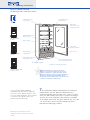
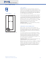
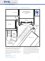
The Sub-Zero Model 601RG all
refrigerator with glass door is available in
your choice of the framed, overlay or stain-
less steel design application. Three stainless
steel finishes are offered—classic (/S),
platinum (/P) and carbon (/B).
This handsome addition to Sub-Zero’s inventory of
models offer
s y
ou the ability to complement the
commer
cial looking kitchen with ease
. There are, obvi
-
ously, no door shelves, but there is no loss of storage
space in this unit. A roll-out utility drawer is available
as an option. Even with the glass door on this unit, you
can assure your clients that this model still meets
Department of Energy numbers.
6
0
1
R
G
Model 601RG/S (P/B)
Stainless Steel
Model 601RG/O
Overlay
M
odel 601RG/F
F
ramed
Front venting allows unit
to be completely built in
Removable kickplate
F
our-sided
magnetic gaskets
A
djustable spill-proof
glass shelves
Serial and model
number plate
T
riple-pane
U
V resistant low-
energy glass door
High humidity
compartment
Hermetically sealed
refrigeration units
E
gg container
Lighted electronic
control panel
Door closers
(Stainless steel design shown)

36"
(914)
24"
(610)
73"
(1854)
36"
(914)
36
1
/16"
(916)
35
1
/4"
(895)
23
7
/8"
(606)
BEHIND
FRAME
3
/8" (10)
FRAME
EXTENSION
Planning Information
Built-In Model 601RG
2
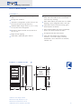
OVERALL DIMENSIONS
FEATURES
36" (914) wide all refrigerator with glass
door
Energy Star qualified
Sub-Zero's refrigeration system ensures the
freshest food and energy efficiency
Shallow-depth design means access is easy
to any area of the refrigerator
Electronic digital controls are up front and
easy to use
Bright interior lighting
Adjustable, spill-proof glass shelves
High-humidity crisper drawer is large and
deep with removable divider and smooth
sides for easy cleaning
Door alarm will let you know with an audible
beeping if your refrigerator door is left ajar
Triple-pane UV-resistant low-energy glass
door improves insulation
Front venting allows unit to be completely
b
uilt in and serviced from the front
UL approved for US and Canada
Two, five and twelve year residential
warranty – exclusions apply; warranty
information can be found on our website,
subzero.com
Dimensions in parentheses are in
millimeters unless otherwise specified.
Stainless steel design shown.
Dimensions ma
y v
ary b
y
±
1
/8" (3).

Planning Information
Built-In Model 601RG
Dimensions in parentheses are in
millimeters unless otherwise specified.
3
SPECIFICATIONS
M
odel 601RG All Refrigerator
w
ith Glass Door
Overall Width 36" (914)
Overall Height 73" (1854)
Overall Depth 24" (610)
Refrigerator Capacity 20.1 cu ft (569 L)
M
inimum Height (levelers in) 72
3
/4"
(1848)
Door Swing Clearance 36
1
/1
6
" (916)
Electrical Requirements 115 V AC, 60 Hz, 15 amp circuit
Annual Energ
y Usage 400 kWh / $ 37
(based on 9.06 cents per kilowatt hour)
Energy Star Qualified
Shipping Weight Framed – 400 lbs (181 kg)
Overlay – 400 lbs (181 kg)
Stainless Steel – 430 lbs (195 kg)
Special Note Model 601RG has a triple-pane
UV-resistant low-energy glass door
Specifications are subject to change without notice.
MODEL OPTIONS
Framed Design 601RG/F
Overlay Design 601RG/O
Classic Stainless Steel 601RG/S
Platinum Stainless Steel 601RG/P
Carbon Stainless Steel 601RG/B
Y
ou must allow 90 days from order to
delivery for platinum and carbon finishes.
A CCESSORIES
Side panels in white, almond and
classic stainless steel
Extended framed handle
Stainless steel and polished
chrome handles for overlay design
Roll-out deli basket
Dozen egg container with lid
90˚ and 105˚ door stop kits
Accessories are available through your
Sub-Zero dealer. To obtain local dealer
information, visit the Locator section of
our website, subzero.com.

Planning Information
Built-In Model 601RG
Dimensions in parentheses are in
millimeters unless otherwise specified.
4
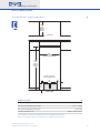
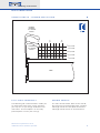
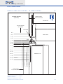
INSTALLATION SPECIFICATIONS
72
3
/4"
(1848)
ROUGH
OPENING
HEIGHT
35
1
/2"
(
902)
R
OUGH OPENING WIDTH
24"
(610)
ROUGH
OPENING
D
EPTH
11"
(279)
24"
(610)
LOCATE ELECTRICAL
WITHIN SHADED AREA
6"
(152)
E
FRONT VIEW
TOP VIEW
DIMENSIONS
Finished Rough Opening Width 35
1
/2" (902)
Finished Rough Opening Height 72
3
/4" (1848)
Finished Rough Opening Depth 24" (610)
Location of Electrical Within shaded area
See Installation Instructions shipped with unit for detailed specifications.
Refer to the Sub-Zero Design Guide pdf file for additional specifications.

Planning Information
Built-In Model 601RG
Dimensions in parentheses are in
millimeters unless otherwise specified.
5
INSTALLATION NOTES
R
efer to the illustrations and specifications
for overall dimensions, finished rough opening
dimensions and installation specifics.
A
llow the door to open a minimum of 90˚ or
you'll have problems removing drawers. With
the door opening at 90˚, you may have to move
drawers slightly to clear the door interior. Refer
to the minimum door swing clearance in the
specifications chart.
For corner installations, allow for a minimum
3" (76) filler so that the door can open to 90˚.
If you're using raised panels, consider using a
wider filler. A 90˚ door stop is available as an
accessory.
When units are installed side by side, a filler
strip is recommended. The width of this filler
strip will vary depending on the configuration
and panels you use. An anchoring kit may also
be used to attach two units together. This kit is
available through your Sub-Zero dealer.
Be sure to add the filler strip width to your
finished rough opening dimension. In any side-
by-side installation without a filler strip, add an
additional
1
/2" (13) to y
our combined number
s.
This will allow for the proper width.
Refer to the full-scale illustrations at the end
of this section for specifics on door openings
and filler size alternatives.
If your client has chosen the stainless steel
design, the unit will be shipped complete with
wrapped stainless steel doors and handle
hardware. You will not have to install front
panels.
If y
our client has chosen the fr
amed or
overlay design, you will be adding front panels
to give the unit the custom Sub-Zero look. The
overlay design also allows you to add your own
handles, or you may choose accessory handles
av
ailable through your Sub-Zero dealer. Refer to
pages
6
–
10 for detailed information on adding
panels.
T
he refrigerator door panel must include a
cut-out to accommodate the window. Refer to
the panel specifications for exact dimensions.
The glass portion of the door must be exposed
a
nd not covered by any part of the panel.
A 115 volt, 60 Hz, 15 amp electrical supply
is required. The supply circuit for this appliance
must be protected by a 15 amp fuse or circuit
breaker. It is recommended that a separate
circuit, serving only this appliance, be provided.
All Built-In models are equipped with a 6'
(1.8 m) power supply cord with a 3-prong
grounding plug which must be plugged into a
mating 3-prong grounding type wall receptacle.
Locate electrical within the shaded area shown
in the installation illustration.
You must follow all National Electrical Code
regulations. In addition, be aware of local codes
and ordinances when installing your service.
To prevent the unit from tipping forward and
provide a stable installation, the unit must be
secured in place with an anti-tip blocking kit. If
there is a solid soffit above the unit with clear-
ance between the unit and the soffit of 1" (25)
or less, you won't need to block the unit.
For installations with clearances of more
than 1" (25), you must block the unit with the
anti-tip bloc
king kit (wood block and hardware)
provided with each Built-In unit.
Refer to the Built-In Installation Instructions
packed with the appliance, which provides
step-by-step procedures for making sure the
unit is installed properly.

Planning Information
Built-In Model 601RG
Dimensions in parentheses are in
millimeters unless otherwise specified.
6
ADDING PANELS
In your plan for panels, be sure you are working with the
Sub-Zero panel design family called for in your design. If
you have chosen the stainless steel design, the unit will be
shipped complete with wrapped stainless steel doors and
h
andle hardware. You will not have to install front door
panels.
If you and your client have ordered a framed or overlay
design model, you will be adding panels to give the unit
the custom Sub-Zero look. Specifications on the following
pages provide installation considerations for framed and
overlay door panels.
Side panels can be used with the framed, overlay and
stainless steel design applications. Refer to specifications
on page 10.

Planning Information
Built-In Model 601RG
Dimensions in parentheses are in
millimeters unless otherwise specified.
7
FRAMED PANELS
Framed door panel
1
/4" (6) thick or less
Framed door panel thicker than
1
/4" (6)
FRAMED PANELS
If the thickness of the custom panels is less than
1
/4"
(6), they must be backed up with a sheet of shim material
to build the total thickness to
1
/4" (6). If the panel is thicker
than
1
/4" (6), an edge must be routed around the panel to
ensure a proper fit. Refer to the illustrations on this page.
I
MPORTANT NOTE:
R
outing, recessing or optional
extended handles may be required on raised panels for
finger clearance under the handle. Refer to the full-scale
illustrations on pages 11–14.
IMPORTANT NOTE: The weight of each panel cannot
exceed 50 lbs (23 kg).
The traditional framed models come with an 11" (279)
louvered grille and elegant full-length handle. Optional
extended full-length handles that provide additional finger
clearance for raised panels are available through your
Sub-Zero dealer. To obtain local dealer information, visit
the Locator section of our website
, subzero.com.
To install framed panels, refer to the installation instruc-
tions shipped with each unit
. These instructions can also
be found on our website, subzero.com.
The refrigerator door panel must include a cut-out to
accommodate the window. Refer to the chart below for
exact dimensions. The glass portion of the door must be
exposed and not covered by any part of the panel.
FRAMED PANEL DIMENSIONS
WIDTH HEIGHT
Door P
anel 34
1
/8" (867) 58
15
/16" (1497)
Handle Recess Location A – 29
15
/32" (749)
Window Cut-Out 25
3
/8" (645) 41
3
/16" (1046)
Window Cut-Out Location B – 4
3
/8" (111)
Maximum Panel Weight 50 lbs (23 kg)
PANELS
1
/4" (6) THICK OR LESS
1
/4" (6) Panel
Trim reveal
1
/4" (6) min
PANELS THICKER THAN
1
/4" (6)
Trim reveal
1
/4" (6) min
Rout to
1
/4" (6)
thickness
B
W
H
A
B B
13
3
/8" (340)
C
14" (356) 1
Framed Door Panel

Planning Information
Built-In Model 601RG
Dimensions in parentheses are in
millimeters unless otherwise specified.
8
OVERLAY PANELS
Three panel assembly—cross section
Door/ Drawer /
Grille Trim
1
/16" (2)
5
/32" (4)
1
/4" (6) Backer Panel
5
/1
6
" (
8)
min
.
10"
(3)
Spacer Panel
Overlay Panel
Three panel assembl
y—rear view
Spacer Panel
Overlay Panel
1
/4" (6)
Backer
Panel
.10"
(3)
~
3
/4"
(19)
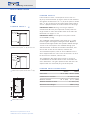
OVERLAY PANELS
The overlay design allows decorative panels to cover the
door trim for a more seamless appearance that blends
with the design of the room. To achieve this look, the
most common way is to work with three panels—the
decorative overlay panel, a .10" (3) spacer panel and a
1
/4"
(6) backer panel. Depending on your cabinet manufacturer,
this could be one panel routed for different dimensions or
more likely, three different panels.
Regardless of the physical construction of the panels
(routing or three panel assembly), you will need to follow
the exact dimensions and panel placement to ensure a
proper fit.
The top illustration on this page is a cross section view of
the three panel assembly showing placement of the
door / drawer/ grille trim. The bottom illustration shows a
rear view of the three panel assembly and critical dimen-
sions, standard for all overlay models.
Overlay models will come with no handle hardware,
because the beauty of this design is that you can match
the surr
ounding cabinetry hardware. For overlay door panel
dimensions, refer to specifications on page 9.
IMPOR
TANT NOTE:
Keep in mind that the Sub-Zer
o door
panels have the potential for hitting adjacent cabinets
and/or countertops when they are opened. You need to be
aw
are of your surrounding cabinetry and space limitations
when using the overlay models. Refer to the full-scale
illustrations on pages 13 –14.
IMPORTANT NOTE: The weight of each door panel
assembly cannot exceed 50 lbs (23 kg). The total thick-
ness of all panels for an overlay model must be at least
5
/8" (16) thick.
To install overlay panels, refer to the installation instruc-
tions shipped with each unit
. These instructions can also
be found on our website, subzero.com.
Do not exceed the dimensions listed for the overlay
grille panel. The decorative panel cannot be any larger
or it ma
y restrict the air flow to the compressor area
and cause problems with the operation of the unit.

A
W
H
A A
13
1
/2" (343)
A
Overlay Door Panel
Planning Information
Built-In Model 601RG
Dimensions in parentheses are in
millimeters unless otherwise specified.
9
OVERLAY PANELS
The refrigerator door panel must include a cut-out to
accommodate the window. Refer to the chart below for
exact dimensions. The glass portion of the door must be
exposed and not covered by any part of the panel.
OVERLAY PANEL DIMENSIONS
WIDTH HEIGHT
Door Panel 34
7
/1
6
" (875) 59
1
/4" (1505)
Door Spacer 33
1
/2" (851) 58
5
/16" (1481)
Door Backer 34
1
/8" (867) 58
15
/16" (1497)
Window Cut-Out
25
7
/16" (646) 4
1
1
/4" (1048)
Window Cut-Out Location A – 4
1
/2" (114)
Maximum Weight (panel assembly) 50 lbs (23 kg)

Planning Information
Built-In Model 601RG
Dimensions in parentheses are in
millimeters unless otherwise specified.
10
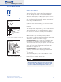
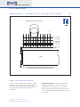
SIDE PANELS
Side panels can be used with the framed, overlay and
stainless steel design applications. When planning for side
panels with the installation of the Built-In model, you need
to be aware of space configuration to achieve a pleasing
fit. Depending on the exact panel you are using with your
unit, the height of the panel will vary.
Cut-outs around the toe kick and grille area are required if
a
1
/4" (6) thick panel will be inserted into the main frame
channel. The panel will need to be 24" (610) deep. Refer to
the illustration on this page for placement of toe kick and
grille area cut-outs. If a
3
/8" (10) thick panel is used, the
panel will abut the main frame and should be 23
7
/8" (606)
deep. The toe kick area may or may not be cut out
depending on the look you want to achieve.
IMPORTANT NOTE: The use of side panels may change
the width of your rough opening.
HARDWARE CONSIDERATIONS
Overlay models come without handle hardware. The
beauty of this design is that you can match the surround-
ing cabinet hardware. You or the cabinet manufacturer
must provide handle hardware to match the overall deco-
rating scheme.
The handle hardware must be installed before installing
the panel assembly. Use larger D-style handles. If screws
with thick heads are used, the screws will need to be
countersunk into the door before the panel is put into
place
. Refer to the full-scale illustr
ations on pages 1
1–12
for handle hardware considerations.
IMPORTANT NOTE: Sub-Zero does not recommend using
single pull knobs on any of its Built-In models.
Optional stainless steel handles are available in a variety of
diameter
s and lengths in the classic, platinum and carbon
stainless steel finishes and polished chrome. Contact
your Sub-Zero dealer for specifics. To obtain local dealer
information, visit the Locator section of our website,
subzer
o.com.
SIDE PANELS
Cut-outs for grille and toe kick area
4"
(102)
3" (76)
23
7
/8" (
606)
B
EHIND FRAME
6

Planning Information
Built-In Model 601RG
Dimensions in parentheses are in
millimeters unless otherwise specified.
11
FULL-SCALE TEMPLATES
The following full-scale illustrations enable you
to under
stand some of the unique situations
you may face as you design the Built-In units
into homes. These templates can be easily
photocopied or used in y
our tr
acings.
HANDLE PROFILE
The full-scale illustration above shows handle
placement for the fr
amed a
pplication standard
full-length handle and the optional extended
full-length handle shown in the dashed line.
1
1
/4"(
32)
P
ANEL
1"(25) PANEL
1
/4"(
6)
P
ANEL
1
/2"(13) PANEL
3
/4"(19) PANEL
O
PTIONAL
EXTENDED
FULL-LENGTH
HANDLE
S
TANDARD
FULL-LENGTH
HANDLE
DOOR
1
/4"(
6)
FRAMED PANEL
1"
(25)
2"
(
51)
3"
(
76)
HANDLE PROFILE – FRAMED APPLICATION

Planning Information
Built-In Model 601RG
Dimensions in parentheses are in
millimeters unless otherwise specified.
12
1
1
/4" (32) PANEL
1" (25) PANEL
1
/4" (
6) PANEL
1
/2" (
13) PANEL
3
/4" (19) PANEL
5
/8" (16) PANEL
DOOR
1
/4" (
6)
APPROXIMATE THICKNESS OF WRAPPED STAINLESS STEEL DOOR
NOTE: FOR OVERLAY APPLICATIONS, OPTIONAL STAINLESS STEEL HANDLE
MUST BE MOUNTED ON PANEL MINIMUM 5/8" (16) THICK.
1"
2"
(
51)
3"
(
76)
S
TANDARD STAINLESS STEEL HANDLE
PANEL AND HANDLE PROFILE
The full-scale illustr
ation a
bove shows handle
placement for the standard stainless steel
handle on the wrapped stainless steel door and
on overla
y panel applications shown in the
dashed line
.
IMPORTANT NOTE: For overlay applications,
the optional stainless steel handle must be
mounted on a panel at least
5
/8" (16) thick.
For overlay applications, mount door handles
close to the opening edge of the door for ease
of opening
.
HANDLE PROFILE – STAINLESS STEEL / OVERLAY APPLICATIONS

1
1
/
4
"
(32)
PA N
EL
1"
(25)
PA N
EL
*
1
/
4
"
(6)
PA N
EL
1
/
2
"
(13)
PA N
EL
3
/
4
"
(19)
PA N
EL
130˚ DOOR OPENING
WITH 2" (51) FILLER STRIP
(
TOP VIEW)
OPTIONAL
FRAMED EXTENDED
FULL-LENGTH HANDLE
STANDARD
FRAMED
FULL-LENGTH
HANDLE
D
OOR CLOSED
DOOR OPEN @ 130˚
HINGE
2" (51)
F
ILLER STRIP
MAIN FRAME
A
LLOW FOR FILLER LAP
BEHIND FLANGE
APPROX
PROFILE OF
STAINLESS
STEEL DOOR
AND HANDLE
OVERLAY PANEL
3/4" (19) THICK
(NOMINAL)
S
UB-ZERO UNITSUB-ZERO UNIT
Planning Information
Built-In Model 601RG
Dimensions in parentheses are in
millimeters unless otherwise specified.
13
The full-scale illustration above shows the panel
and handle profile of a 130˚ door opening with
2" (51) filler strip for framed applications.
Interference of door panels with handles at
maximum door s
wing ma
y require the use of an
optional 90˚ door stop available through your
Sub-Zero dealer.
To obtain local dealer information, visit the
Locator section of our website, subzero.com.
The full-scale illustration on the following page
lets you see what considerations you need to
mak
e for any overla
y panel applications, and
how they may interact with adjacent cabinets
and/or countertops.
PANEL AND HANDLE PROFILE – 130˚ DOOR OPENING
*
Appr
oximate thic
kness of wr
a
pped
stainless steel door
.

Planning Information
Built-In Model 601RG
Dimensions in parentheses are in
millimeters unless otherwise specified.
14
1
1
/4
"
(32)
PA N
EL
1"
(25)
PA N
EL
*
1
/4
"
(6)
PA N
EL
1
/2
"
(13)
PA N
EL
3
/4
"
(19)
PA N
EL
1
1
/4
"
(32)
1
1
/2
"
(38)
1
3
/4
"
(44)
0"
(0)
1"
(25)
2"
(51)
2
1
/4
"
(57)
2
1
/
2
"
(63)
2
3
/
4
"
(70)
3"
(76)
3
1
/4
"
(83)
3
1
/
2
"
(89)
1
/4
"
(6)
1
/2
"
(25)
3
/4
"
(19)
HINGE
OVERLAY PANEL
3/4" (19) THICK (NOMINAL)
DOOR CLOSED
DOOR OPEN @ 90˚
90˚ DOOR OPENING
(TOP VIEW)
M
AIN FRAME
NOMINAL OVERALL
WIDTH OF SUB-ZERO
S
UB-ZERO UNIT
23
7
/8" (606) TO REAR
O
F SUB-ZERO
OVERLAY PANEL APPLICATION – 90˚ DOOR OPENING
*
Appr
oximate thic
kness of wr
a
pped
stainless steel door
.
-
 1
1
-
 2
2
-
 3
3
-
 4
4
-
 5
5
-
 6
6
-
 7
7
-
 8
8
-
 9
9
-
 10
10
-
 11
11
-
 12
12
-
 13
13
-
 14
14


Ask a question and I''ll find the answer in the document
Finding information in a document is now easier with AI
Related papers
-
Sub-Zero 600 Series Refrigeration Design Guide
-
Sub-Zero 601R User manual
-
-
-
Sub-Zero 611/O Specification
-
-
-
-
-
