Thermador HMCB30WS User manual
- Category
- Cooker hoods
- Type
- User manual
This manual is also suitable for

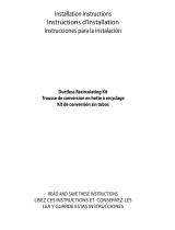
Installation
INSTRUCTIONS
Thermador Masterpiece
®
Chimney Wall Hoods
THERMADOR.COM

THERMADOR.COM
Installation
INSTRUCTIONS
Thermador
Masterpiece
®
Chimney Wall Hoods
Table of Contents (English) ................................................................... 3
Table de Matières (Français) ................................................................. 22
Índice de Capitulos (Español)................................................................ 41
Models |
Modèles |
Modelos:
HMCB30WS
HMCB36WS

Installation Instructions English | 3 |
Table of
Contents
Safety ................................................................................. 4
Important Safety Instructions ..................................... 4
Advance Planning .............................................................. 7
Before You Begin ........................................................ 7
General Information ................................................... 8
Installation Preparation...................................................... 9
Installation Considerations ......................................... 9
Electrical Requirements .............................................. 10
CommonDuctingCongurations...............................12
Hood Transition .......................................................... 12
Installation Instructions....................................................... 13
Wall Installation ........................................................... 14
Electrical Connection .................................................. 15
Remote Control Installation (optional)........................ 17
Duct Cover Extension (optional)................................. 18
Recirculating Kit (optional).......................................... 19
Charcoal Filter Replacement (optional)...................... 20
Installer Checklist and Service ........................................... 21
Installer Checklist ........................................................ 21
Before Calling Service ................................................ 21
Product Data Rating Plate .......................................... 21
Safety
Definitions
WARNING
This indicates that death or serious injuries may occur as a
result of non-observance of this warning.
CAUTION
This indicates that minor or moderate injuries may occur
as a result of non-observance of this warning.
NOTICE: This indicates that damage to the appliance or
property may occur as a result of non-compliance with this
advisory.
Note: This alerts you to important information and/or tips.
This THERMADOR® appliance is made by
BSH Home Appliances Corporation
1901 Main Street, Suite 600
Irvine, CA 92614
Questions?
1-800-735-4328
www.thermador.com
We look forward to hearing from you!

Installation InstructionsEnglish | 4 |
Safety
IMPORTANT SAFETY INSTRUCTIONS
READ AND SAVE THESE INSTRUCTIONS
INSTALLER: Save these instructions for the local electrical
inspector’s use. Please leave these instructions with this
unit for the owner. Show the owner the location of the
circuit breaker or fuse. Mark it for easy reference.
OWNER: Please retain these instructions for future
reference.
WARNING
If the information in this manual is not followed exactly,
reorshockmayresultcausingpropertydamageor
personal injury.
WARNING
If the information in this manual is not followed
exactly,reorshockmayresultcausingproper-
ty damage, personal injury or death.
- DONOTstoreorusegasolineorotherammable
vapors and liquids in the vicinity of this or any other
apppliance.
- WHAT TO DO IF YOU SMELL GAS
• DO NOT try to light any appliance.
• DO NOT touch any electrical switch.
• DO NOT use any phone in your building.
• Immediately call your gas supplier from a
neighbor’s phone. Follow the gas supplier’s
instructions.
• Ifyoucannotreachyourgassupplier,callthere
department.
- Installation and service must be performed by an
authorized servicer, service agency or the gas supplier.
WARNING
Turn off power circuit at service panel and lock out panel
before wiring this appliance. Requirement: 120 VAC, 60
Hz 15 A. Allow the appliance to cool after the power has
been turned off before servicing the appliance.
WARNING
Automatically Operated Device
To reduce the risk of injury disconnect from power supply
before servicing.
WARNING
TO REDUCE THE RISK OF FIRE, ELECTRIC SHOCK,
OR INJURY TO PERSONS, OBSERVE THE
FOLLOWING:
• Use this unit only in the manner intended by the
manufacturer. If you have questions, contact the
manufacturer at the address or telephone number
listed on the back page.
• Before servicing or cleaning unit, switch power off at
service panel and lock the service disconnecting
means to prevent power from being switched on
accidentally. When the service disconnecting means
cannot be locked, securely fasten a prominent
warning device, such as a tag, to the service panel.
WARNING
DO NOT repair or replace any part of the appliance
unlessspecicallyrecommendedinthemanuals.
Improper installation, service or maintenance can cause
injury or property damage. Refer to this manual for
guidance. All other servicing should be done by an
authorized servicer.
WARNING
ELECTRICAL SHOCK HAZARD
• DO NOT remove connections.
• DO NOT use an extension cord.
• Failure to follow these instructions can
resultindeath,re,orelectricalshock.

Installation Instructions English | 5 |
IMPORTANT SAFETY INSTRUCTIONS
READ AND SAVE THESE INSTRUCTIONS
Grounding Instructions
WARNING
Improper grounding can result in a risk of electric shock.
This appliance must be grounded. In the event of an electri-
cal short circuit, grounding reduces the risk of electric shock
by providing an escape wire for the electric current.
Be sure your appliance is properly installed and grounded
byaqualiedtechnician.Installation,electricalconnections
and grounding must comply with all applicable codes.
If required by the National Electrical Code (or Canadian
Electrical Code), this appliance must be installed on a sepa-
rate branch circuit.
WARNING
Toreducetheriskofreorelectricalshock,DO NOT use
this appliance with any solid state speed device.
Safety Codes and Standards
This appliance complies with one or more of the following
Standards:
• UL 507, The Standard for the Safety of Electric Fans
• CSA C22.2 No. 113, Fans and Ventilators
It is the responsibility of the owner and the installer to de-
termine if additional requirements and/or standards apply
tospecicinstallations.
CAUTION
Unit is heavy and requires at least two people
or proper equipment to move and install.
Hidden surfaces may have sharp edges. Use
caution when handling the appliance. Failure
to do so may result in property damage or
personal injury.
WARNING
State of California Proposition 65 Warnings:
This product can expose you to chemicals including vinyl
chloride, which is known to the State of California to
cause cancer and birth defects or other reproductive
harm. For more information go to
www.P65Warnings.ca.gov.
Never modify or alter the construction of the appliance.
For example, do not remove panels, wire covers or
brackets/screws.
CAUTION
For general ventilating use only. DO NOT use to exhaust
hazardous or explosive materials and vapors.
WARNING
Toreducetheriskofre,useonlymetalductwork.
Useaqualiedinstaller.
Remove all tape and packaging before using the
appliance. Destroy the packaging after install. Never allow
children to play with packaging material.
WARNING
TO REDUCE THE RISK OF FIRE, ELECTRIC SHOCK,
OR INJURY TO PERSONS, OBSERVE THE
FOLLOWING:
• Installation work and electrical wiring must be done
byqualiedperson(s)inaccordancewithall
applicablecodesandstandards,includingre-related
construction.
• Sufcientairisneededforpropercombustionand
exhaustingofgasesthroughtheue(chimney)of
fuel burning equipment to prevent back drafting.
Follow the heating equipment manufacturer’s
guideline and safety standards such as those
published by the National Fire Protection
Association (NFPA), and the American Society for
Heating, Refrigeration and Air Conditioning
Engineers (ASHRAE), and the local code authorities.
• When cutting or drilling into wall or ceiling, do not
damage electrical wiring and other hidden utilities.
• Ducted fans must always be vented to the outdoors.

Installation InstructionsEnglish | 6 |
IMPORTANT SAFETY INSTRUCTIONS
READ AND SAVE THESE INSTRUCTIONS
WARNING
TO REDUCE THE RISK OF A RANGE TOP GREASE
FIRE:
• Never leave surface units unattended at high
settings.
Boilovers cause smoking and greasy spillovers that
may ignite. Heat oils slowly on low or medium
settings.
• Always turn hood ON when cooking at high heat
orwhencookingambéingfood(i.e.CrepesSuzette,
Cherries Jubilee, Peppercorn Beef Flambe).
• Clean ventilating fans frequently. Grease should
notbeallowedtoaccumulateonfanorlter.
• Use proper pan size. Always use cookware
appropriate for the size of the surface element.
WARNING
TO REDUCE THE RISK OF INJURY TO PERSONS IN
THE EVENT OF A RANGE TOP GREASE FIRE,
OBSERVE THE FOLLOWING:
a
• SMOTHERFLAMESwithaclosettinglid,cookie
sheet, or metal tray, then turn off the burner. BE
CAREFULTOPREVENTBURNS.Iftheamesdonot
go out immediately, EVACUATE AND CALL THE
FIRE DEPARTMENT.
• NEVER PICK UP A FLAMING PAN - you may get
burned.
• DO NOT USE WATER, including wet dishcloths or
towels - a violent steam explosion will result.
• Use an extinguisher ONLY if:
a) You know you have a class ABC extinguisher,
and you already know how to operate it.
b) Thereissmallandcontainedintheareawhere
it started.
c) Theredepartmentisbeingcalled.
d) Youcanghttherewithyourbacktoanexit.
a
Based on “Kitchen Fire Safety Tips” published by NFPA.

Installation Instructions English | 7 |
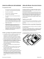
Advance Planning
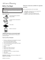
Before You Begin
CAUTION
Before installing, turn power OFF at the service panel.
Lock service panel to prevent power from being turned
ON accidentally.
Parts Included
Hood assembly (lamps and blower
already installed)
8” Metal transition with backdraft
damper
Greaselters
Fastener assortment*
* Hardware provided is for mounting through standard
thickness drywall or plaster into wood studs. Installers
are responsible to provide hardware for other types of
mounting situations.
Tools and Parts Needed
• Ducting as needed (refer to Equivalent Duct Lengths
for Commonly Used Transitions Table)
• Aluminum tape (DO NOT use duct tape)
• 1/2’’ (13 mm) Conduit if required (follow local codes)
• 1’’ (25.4 mm) Strain relief
• Ducting as needed
• Blower
• Flat head and Phillips screwdrivers
• Drill with 3/16’’ (4.76 mm) drill bit
• Circular saw or jigsaw
• 3/8’’ (9.52 mm) nut driver or socket and ratchet
• Wire stripper
• Protective work gloves
IMPORTANT: DO NOT throw away any packaging until
appliance is fully installed.
Optional accessories available for separate
purchase.
Refer to www.thermador.com for more details.
• CHXTHMCB – Telescopic Duct Cover Extension Kit
• RECHMCB – Recirculating Kit
• CHFHMCD – Charcoal Filter Replacement Kit
• REMCPW – Built-In Remote Control Accessory

Installation InstructionsEnglish | 8 |
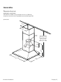
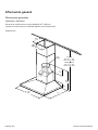
General Information
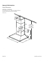
Overall Dimensions
HMCB30WS and HMCB36WS
This model series is 23
3
⁄16’’ (588 mm) in depth and feature
brushed stainless-steel canopy with LED lights.
inches (mm)
30" (762)
36" (914)
23
3
⁄
16
"
(588)
Ø 8"
(200)
30" (762)
36" (914)
23
3
⁄
16
"
(588)
20
9
⁄
16
"
(522)
20
9
⁄
16
"
(522)
20
9
⁄
16
"
(522)
5"
(127)
7"
(177)
13
2
⁄
16
"
(332)
13
2
⁄
16
"
(332)
10
13
⁄
16
"
(275)
10
13
⁄
16
"
(275)
DUCTED
MIN: 32
1
⁄
16
" (814)
MAX: 53
3
/
8
" (1355)
RECIRCULATING
MIN: 32
1
⁄
16
" (814)
MAX: 57
5
⁄
16
" (1455)
DUCTED
MIN: 32
1
⁄
16
" (814)
MAX: 53
3
/
8
" (1355)
RECIRCULATING
MIN: 36
3
⁄
8
" (924)
MAX: 57
5
⁄
16
" (1455)

Installation Instructions English | 9 |
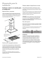
Installation Preparation
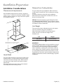
Installation Considerations
Clearances and requirements
Hood installation height above a cooktop, rangetop or
range can vary. To obtain the necessary installation height
above a cooktop, rangetop or range, consult the applian-
ce’s installation manual.
20
9
⁄
16
"
(522)
30" (762) min over a electric cooktop
30" (762) min over a gas cooktop
Hood Width
The hood width should be no less than the width of the
cooking surface. For proper performance, the housing
must cover the entire cooking surface. Where space is
not restricted, a wider hood can be used to increase
capture area.
For proper performance, the hood must be centered
horizontally above the cooking surface.
Distance From Cooking Surface
For gas cooktop & range installations: Mount the hood
so the bottom is at least 30” (76.2 cm) above the cooking
surface.
For electric/induction cooktop & range installations:
Mount the hood so the bottom is at least 30” (76.2 cm)
above the cooking surface.
NOTICE: The hood could incur some damage from heat
if a THERMADOR MASTERPIECE
®
series cooktop is opera-
ted with multiple burners at high settings under a hood that
is installed at minimum clearances.
Unit Weight
This vent hood is heavy. Adequate structure and support
must be provided in all types of installations.
When calculating the load for the housing support
system, be sure to consider the weight of the
ventilation unit.
Unit Weight
30’’ (76 cm) 50.2 lb (22.8 kg)
36’’ (91 cm) 53.3 lb (24.2 kg)
IMPORTANT:
The supplied weights address only the ventilation unit and
blower. Installer must account for weight of any materials
of construction when calculating the total dead weight
load of installation, including but not limited to: wall, tile,
mortar,plaster,brick,nishes,partitions,andothersimilar-
ly incorporated architectural and structural items. It is the
responsibility of the owner and the installer to determine if
additionalrequirementsand/orstandardsapplytospecic
installations.

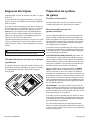
Installation InstructionsEnglish | 10 |
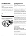
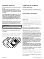
Electrical Requirements
The unit requires a 120V AC, 60Hz. 15A branch circuit.
The hood should only be connected to a dedicated circuit
(with ground) that has been installed according to relevant
regulations.
Check your local building codes for proper method of ins-
tallation. In the U.S., if there are no applicable local codes,
this unit should be installed in accordance with the National
Electric Code ANSI/NFPA No. 70, Current Issue. In Canada,
installation must be in accordance with the CAN 1- B149.1
and .2 - Installation Codes for Gas Burning Appliances and/
or local codes.
The appliance must be grounded. In the event of an elec-
trical short circuit, grounding reduces the risk of electric
shock by providing a wire that allows the electric current to
escape.
WARNING
The appliance must be grounded.
Electrical Data on the Data Rating Label
Data, including the model and serial number, is located
on the product data rating label inside the appliance,
visibleafterremovalofthelterframe.
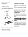
Ductwork Preparation
Discharge Direction
The exhaust air is discharged upwards through a duct.
The hood can be mounted only with a vertical discharge.
Ducting Recommendations
Proper performance is dependent upon proper ducting.
Local building codes may require the use of make-up air
systems when using ducted ventilation systems greater than
speciedcubicfeetperminute(CFM)ofairmovement.
ThespeciedCFMvariesfromlocaletolocale.Itisthe
responsibility of the owner and the installer to determine if
additionalrequirementsand/orstandardsapplytospecic
installations.
DO NOT USE FLEXIBLE DUCT; it creates back pressure/
air turbulence and reduces performance. Always use metal
ductwork.
Always install a metal vent cover where the ductwork exits
the house. Hood must be vented to the outside of building
only.
COLD WEATHER installations should have an additional
backdraft damper installed to minimize backward cold air
owandanonmetallicthermalbreaktominimizeconduc-
tion of outside temperatures as part of the ductwork. The
damper should be on the cold air side of the thermal break.
The break should be as close as possible to where the duc-
ting enters the heated portion of the house.
MAKE-UP AIR: Local building codes may require the use of
make-up air systems when using ducted ventilation systems
greaterthanspeciedCFMofairmovement.
ThespeciedCFMvariesfromlocaletolocale.Itisthe
responsibility of the owner and the installer to determine if
additionalrequirementsand/orstandardsapplytospecic
installations.
For safety reasons, ducting should vent directly outdoors
(not into an attic, underneath the house, into the garage or
into any enclosed space).
THERMADOR
®
recommends not exceeding 50 equivalent
length (ft) (15.24 m) of duct.
Keep duct runs as short and straight as possible.
Elbowsandtransitionsttingsreduceairowefciency.
Back to back elbows and “S” turns give very poor delivery
and are not recommended.
A short straight length of duct at the inlet of a remote
blower gives the best delivery.
Hoods are supplied with a 8” (203 mm) round transition. A
locally supplied transition is required for other sizes.
Use “Equivalent Duct Lengths for Commonly Used Transi-
tions” on page 11 to compute permissible lengths for duct
runs to outdoors.

Installation Instructions English | 11 |
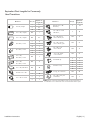
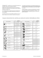
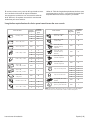
Equivalent Duct Lengths for Commonly
Used Transitions
Size (in)
Eq uivalent
Length (ft)
Size (in)
Eq uivalent
Length (ft)
61.2
61
0
80.7
10 0.6
3¼" x 10", straight N/A1
3¼" x 10", Center
reverse elbow, right
N/
A2
5
3¼" x 14", straight N/A0.7
3¼" x 10", Left
reverse elbow
N/
A1
5
3¼" x 10", Right
reverse elbow
N/
A2
5
612
62
86
82
10
10 2
65
62
2
5
83
82
2
2
10
10
3¼" x 10",
90° elbow, round
N/A5
2’ long, 3¼" x 10" exN/A 20
3¼" x 10",
45° elbow, round
N/A15
3¼" x 10", Flat elbowN/A 20
61
810
82
3¼" x 10", Roof jack
and shutter
N/A
65
61
0
NOTE: These commonly used installation parts can be purchased at a
local hardware store. Thermador does not manufacture all these parts.
Round wall cap
Round roof cap
3¼" x 10" to round
90° elbow,
Duct Piece
3¼" x 10" Center
reverse elbow, left
15N/A
Round to 3¼" x 10"
3¼" x 10" to round
Round to 3¼" x 10"
90° elbow,
Duct Piece
Smooth, straight
90° elbow, round
45° elbow, round

Installation InstructionsEnglish | 12 |
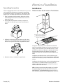
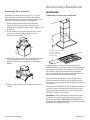
CommonDuctingCongurations
B
D
E
A
A
B
E
B
E
B
C
A
RECIRCULATING MODE VENTING THROUGH THE WALL VENTING THROUGH THE CEILING
A. 8” round transition
B. 8” round duct system
C. 90° elbow
D. Recirculating kit
E. Installation height:
Gas range MIN: 30” (76.2 cm)
Electric range MIN: 30” (76.2 cm)
NOTE: Theguredoesnotrepresentallcongurationsorinstallationmethods.TheimageistobeusedasaguideONLY.
Venting Methods
This hood is factory set for venting through the roof (vertical
discharge) or wall (horizontal discharge). A 8” (203 mm)
round duct system is needed for installation (not included).
NOTE: Flexible duct is not recommended. Flexible
ductwork creates back pressure and air turbulence that
greatly reduce performance.
Vent system can terminate either through the roof or wall.
Always install a metal vent cover where the ductwork exits
the house.
For Non-Vented (recirculating) Installations
If it is not possible to vent cooking fumes and vapors to
the outside, the hood can be used in the non-vented
(recirculating) version, using the recirculating kit . Fumes
and vapors are recycled through the round grid.
See optional accessories section.
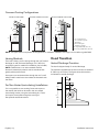
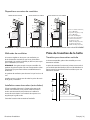
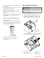
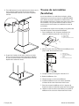
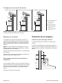
Hood Transition
Vertical Discharge Transition
The hood is shipped ready for vertical discharge.
The transition supplied with the hood connects to standard
8"(203mm)roundduct.Thegureshowsthetransition
connected for vertical discharge.
13
9
⁄
16
"
(345)
7"
(177)
4
3
⁄
4
”
(120)
CL

Installation Instructions English | 13 |
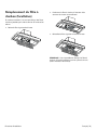
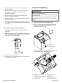
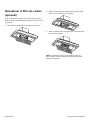
Assembly of the Transition
A minimum height clearance of 4
5
⁄16’’ (110 mm) is needed
above the hood for transition mounting. See “General
Information” on page 8 for overall hood dimensions.
1. Depending on direction of discharge, align mounting
holes at base of transition with the mounting holes on
the top of the hood.
2. Fasten transition to hood using four (4)
1
⁄4’’ (6 mm)
sheet metal screws included with hood.
3. Seal connection between transition and hood with
aluminum tape. DO NOT use duct tape. Ensure that
the connection is completely sealed.
4. Remove tape holding damper closed.
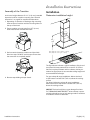
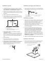
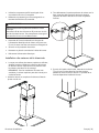
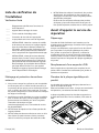
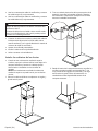
Installation Instructions
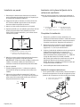
Installation
Determine installation height
20
9
⁄
16
"
(522)
30" (762) min over a electric cooktop
30" (762) min over a gas cooktop
Thegureaboveindicatesatypicalinstallationofthehood.
An optional chimney extension kit to reach 9’-12’ (274 to
366 mm) may be purchased. Add or subtract chimney ex-
tensions as appropriate to accommodate ceiling height and
recommended hood height.
For gas cooktop & range installations: Mount the hood
so the bottom is at least 30” (76.2 cm) above the cooking
surface.
For electric/induction cooktop & range installations:
Mount the hood so the bottom is at least 30” (76.2 cm)
above the cooking surface.
NOTICE: The hood could incur some damage from heat
if a THERMADOR MASTERPIECE
®
series cooktop is opera-
ted with multiple burners at high settings under a hood that
is installed at minimum clearances.

Installation InstructionsEnglish | 14 |
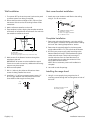
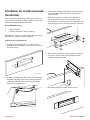
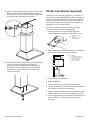
Wall installation
1. Turn power OFF at the service panel. Lock service panel
to prevent power from being turned ON.
2. Ensure that the minimum height of 30” (762 mm) from
the bottom of the hood to the cooking surface will be
maintained.
3. Mark a reference centerline on the wall.
4. Tape template in place, aligning the template centerline
and bottom of template with hood bottom line and with
the centerline marked on the wall.
Ver tical Centerline
C
L
LLAW RAER
ETALPMET GNITNUOM
EGDE MOTTOB NGILA
ENIL LICNEP HTIW
MOTTOB GNITACIDNI
DOOH EHT FO
thgieH noitallatsnI
TROPPUS LLAW RAER RO SDUTS HGUORHT SELOH TOLIP "61/3 )OWT( 2 LLIRD
eniL latnoziroH
A
B
C
A. Centerline
B. Fastener locations
C. Mounting height reference (hood bottom line)
5. Mark centers of the fastener locations through the
template to the wall.
IMPORTANT: All screws must be installed into wood.
If there is no wood to screw into, additional wall framing
supports may be required.
6. Remove the template.
7. Drill
3
⁄16” (4.8 mm) pilot holes at all locations where
screws are being installed into wood.
8. Install the 2 - 5 x 45 mm mounting screws. Leave a
1
⁄4”
(6.4 mm) gap between the wall and the back of the
screw head to slide range hood into place.
1
/
4
"
(6.4)
Vent cover bracket installation
1. Attachventcoverbrackettowallushtotheceiling
using 2 - 5 x 45 mm screws.
A
C
D
B
A. 8 x 40 mm drywall anchors
B. Centerline on wall
C. Vent cover support bracket
D. 5 x 45 mm screws
Complete Installation
1. Determine and make all necessary cuts in the wall for
the vent system. Install the vent system before installing
the hood. See “Venting Requirements” section.
2. Determine the required height for the home power
supply cable and drill a 1
1
⁄4” (3.2 cm) hole at this location.
3. Run the home power supply cable according to the
National Electrical Code or CSA Standards and local
codes and ordinances. There must be enough
1
⁄2”
conduit and wires from the fused disconnect (or
circuit breaker) box to make the connection in the
hood’s electrical terminal box.
NOTE: Do not reconnect power until installation is
complete.
4. Use caulk to seal all openings.
Installing the range hood
1. Using 2 or more people, hang range hood on 2
mounting screws through the mounting slots on back of
the hood.
A Upper mounting screws
B Security screws
A
B

Installation Instructions English | 15 |
2. Mark with a pencil the lower mounting holes location.
3. Uninstall the hood assembly, and drill
3
⁄16” (4.8 mm)
pilot holes at marked locations.
4. Hang the range hood again on 2 upper mounting screws.
5. Level the range hood and tighten upper mounting
screws.
6. Install 2 - 5 x 45 mm lower mounting screws and
tighten. Use the optional wall anchors if needed.
Connect Vent System
1. Fit vent system over the exhaust outlet.
2. Measurefromthebottomoftheairdeectortothe
bottom of the hood outlet. Cut the ductwork at the
measured dimension.
Dimension
to measure
Roof
outlet
Wall
outle
t
3. Seal connection with clamps.
4. Check that back draft dampers work properly.
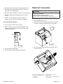
Electrical Connection
WARNING
Electrical Shock Hazard
Disconnect power before servicing.
Replace all parts and panels before operating.
Failure to do so can result in death or electrical shock.
• Disconnect power.
• Remove terminal box cover.
• Remove the knockout in the terminal box cover and
install a UL listed or CSA approved
1
⁄2” strain relief.
C
B
A
A Juction Box
B Knockout
C Juction Box cover
• Run home power supply cable through strain relief,
into terminal box.
A. Home power supply cable
B. UL listed or CSA approved
strain relief
C. Black wires
D. UL listed wire connectors
E. White wires
F. Green (or bare) and yellow-green
ground wires
A
B
C
D
E
F

Installation InstructionsEnglish | 16 |
• Use UL listed wire connectors and connect black wires
(C) together.
• Use UL listed wire connectors and connect white wires
(E) together.
WARNING
Electrical Shock Hazard
Electrically ground blower.
Connect ground wire to green and yellow ground wire
in terminal box. Failure to do so can result in death or
electrical shock.
• Connect green (or bare) ground wire from home power
supply to yellow-green ground wire (F) in terminal box
using UL listed wire connectors.
• Tighten strain relief screw.
• Install terminal box cover.
• Reconnect power.
Install duct covers
• When using both upper and lower vent covers, push
lower cover down onto hood and lift upper cover to
ceiling and install with two mounting screws.
NOTE: For vented installations, the upper vent cover
may be reversed to hide slots.
1. Insert the complete duct cover at an angle and swivel
toward the wall.
2. Carefully pull the top part of the extension upwards.
Screw the left and right sides of the extension to the
mounting bracket with the supplied stainless screws.
3. From inside of hood, screw the supplied
5
⁄8’’ (16 mm)
sheet metal screws through the holes on each side
and along the front into bottom of the extension.
Screw quantity is dependent on hood size.

Installation Instructions English | 17 |
Remote Control Installation
(optional)
Before you begin, read these instructions carefully. It is
recommended that the Remote Control be wired to the
hood after the hood is installed.
REMCPW Parts Included
• 1 – Remote control
• 1 – 30 ft. extension harness
IMPORTANT: Cutting off a connector to the appliance or
to the extension cable kit will void the warranty.
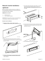
Remote Control Installation
4. Prepare the wall (or similar surface) cutout for
installation as shown below (view is shown facing wall)
13
5
8
/
"
(346)
2
5
8
/
"
(65)
inches (mm)
5. Access the hood’s wiring. Route the 30 ft. extension
harness through the strain relief to the square mounting
clip until it clicks.
6. Route the 30 ft extension harness through the cutout
and connect the harness to the back of the remote
control bracket.
7. Press the bracket inside the cutout. Drill a ¼’’ (6 mm)
tap hole through the bracket holes into the wall.
Mount the bracket to the wall using the four (4) screws
provided.
8. Hook up the wire harness connector inside the bracket
to the terminal on the back side of the remote control.
Use either terminal.
9. Snap the Remote Control into the bracket.

Installation InstructionsEnglish | 18 |
Duct Cover Extension (optional)
On some models, optional duct covers and telescoping
extensionsmaybeusedtollthespacebetweenthehood
and ceiling in wall mount installations. Chimney duct cover
includedwiththerangehoodllthespacebetweenthe
hood and ceiling of 8’ (2.4 m) ceilings. Telescoping exten-
sions accommodate 12’ (3.6 m) ceilings.
Model
Telescopic
Extension
HMWB30WS CHXTHMCB
HMWB361WS CHXTHMCB
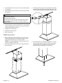
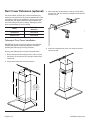
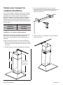
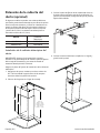
Telescopic Duct Cover Installation
IMPORTANT: Secure the Chimney Hood to the wall after
installing the Extension Mounting Bracket, but before
installing the Telescoping Chimney Extension.
Securing the Telescoping Chimney Extension Bracket
1. Ensure that the minimum height of 30” (762 mm) from
the bottom of the hood to the cooking surface will be
maintained.
2. Locate two studs at the mounting location.
20
9
⁄
16
"
(522)
5"
(127)
13
2
⁄
16
"
(332)
13
2
⁄
16
"
(332)
10
13
⁄
16
"
(275)
10
13
⁄
16
"
(275)
20
9
⁄
16
"
(522)
34"
(863)
20
9
⁄
16
"
(522)
34"
(860)
DUCTED
MIN: 32
1
⁄
16
" (814)
MAX: 53
3
/
8
" (1355)
RECIRCULATING
MIN: 32
1
⁄
16
" (814)
MAX: 57
5
⁄
16
" (1455)
DUCTED
MIN: 34" (860)
MAX: 63" (1600)
RECIRCULATING
MIN: 39" (99)
MAX: 77" (1700)
3. Mount the duct cover bracket on the top of the ceiling
using (2) 1½’’ (38 mm) screws (provided). Ensure that the
bracket is level.
4. Insert the complete duct cover at an angle and swivel
toward the wall.

Installation Instructions English | 19 |
5. Carefully pull the top part of the extension upwards.
Screw the left and right sides of the extension to the
mounting bracket with the supplied stainless screws.
6. From inside of hood, screw the supplied
5
⁄8’’ (16 mm)
sheet metal screws through the holes on each side
and along the front into bottom of the extension.
Screw quantity is dependent on hood size.
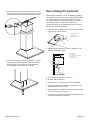
Recirculating Kit (optional)
When used in recirculation mode, To Reduce the Risk of
Fire and Shock use only conversion kit Model RECHMCB.
If it is not possible to vent cooking fumes and vapors to
the outside, the hood can be used in the non-vented
(recirculating) version, using the recirculating kit .
Fumes and vapors are recycled through the round grid.
See optional accessories section.
1. Assembletheairdeectorwiththeductcoverbracket
using (4) 4.2 x 8 mm screws.
C
B
A
A. Mounting screws
B.Airdeector
C. Duct cover bracket
2. Measurefromthebottomoftheairdeectortothe
bottom of the hood outlet.
X
A
C
B
D
E
A.Airdeector
B. Vent clamp
C. X = length to cut vent duct
D. Vent duct
E. Exhaust outlet
3. Cut the duct to the measured size “X.”
4. Removetheairdeector.
5. Slidetheductontothebottomoftheairdeector.
6. Placetheassembledairdeectorandductoverthe
exhaust outlet from the hood.
7. Reassembletheairdeectortotheductcoverbracket
with the four assembly screws.
8. Useducttapeorventclampstosealthedeectorand
the exhaust outlet from the hood.

Installation InstructionsEnglish | 20 |
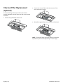
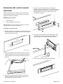
Charcoal Filter Replacement
(optional)
In the reciruclating mode, the air will be recirculated
throughdisposablecharcoalltersthathelpremovesmoke
and odors.
• Removethegreaselterofthehood.
• Positionthecharcoallterinsidethestructureofthe
motor as shown in picture.
• Reinstallthegreaselterontothebottomofthehood.
NOTE:Thecharcoallterscannotbecleaned.Itshouldbe
replaced every 4-6 months (depending on hood usage).
Page is loading ...
Page is loading ...
Page is loading ...
Page is loading ...
Page is loading ...
Page is loading ...
Page is loading ...
Page is loading ...
Page is loading ...
Page is loading ...
Page is loading ...
Page is loading ...
Page is loading ...
Page is loading ...
Page is loading ...
Page is loading ...
Page is loading ...
Page is loading ...
Page is loading ...
Page is loading ...
Page is loading ...
Page is loading ...
Page is loading ...
Page is loading ...
Page is loading ...
Page is loading ...
Page is loading ...
Page is loading ...
Page is loading ...
Page is loading ...
Page is loading ...
Page is loading ...
Page is loading ...
Page is loading ...
Page is loading ...
Page is loading ...
Page is loading ...
Page is loading ...
Page is loading ...
Page is loading ...
-
 1
1
-
 2
2
-
 3
3
-
 4
4
-
 5
5
-
 6
6
-
 7
7
-
 8
8
-
 9
9
-
 10
10
-
 11
11
-
 12
12
-
 13
13
-
 14
14
-
 15
15
-
 16
16
-
 17
17
-
 18
18
-
 19
19
-
 20
20
-
 21
21
-
 22
22
-
 23
23
-
 24
24
-
 25
25
-
 26
26
-
 27
27
-
 28
28
-
 29
29
-
 30
30
-
 31
31
-
 32
32
-
 33
33
-
 34
34
-
 35
35
-
 36
36
-
 37
37
-
 38
38
-
 39
39
-
 40
40
-
 41
41
-
 42
42
-
 43
43
-
 44
44
-
 45
45
-
 46
46
-
 47
47
-
 48
48
-
 49
49
-
 50
50
-
 51
51
-
 52
52
-
 53
53
-
 54
54
-
 55
55
-
 56
56
-
 57
57
-
 58
58
-
 59
59
-
 60
60


Thermador HMCB30WS User manual
- Category
- Cooker hoods
- Type
- User manual
- This manual is also suitable for
Ask a question and I''ll find the answer in the document
Finding information in a document is now easier with AI
in other languages
- français: Thermador HMCB30WS Manuel utilisateur
- español: Thermador HMCB30WS Manual de usuario
Related papers
-
Thermador CHXTHMCB Installation guide
-
Thermador PH36HS Installation guide
-
-
Thermador CHXTHDDW Installation guide
-
Thermador RECHMIB Installation guide
-
Thermador PROFESSIONAL PH30HS User manual
-
-
Thermador HMCB30WS User guide
-
Thermador HMCB36WS User guide
-
Thermador HPCB48NS Installation guide
Other documents
-
IKEA Plumbing Product AA-338705-2 User manual
-
-
-
-
ELICA EVL436S1 Install Instructions Volterra
-
-
Silhouette SR001 The Renoir Installation guide
-
GE PV970NSS Owner's manual
-
ELICA EPL636S1 Installation guide
-
 arietta KIT0102876 Installation guide
