
ge.com
Refrigerators
Bottom Freezer
200D9366P001 49-60489-2 06-07 JR
Safety Instructions . . . . . . . . . . .2, 3
Operating Instructions
Additional Features . . . . . . . . . . . . .8
Automatic Icemaker . . . . . . . . . . .11
Care and Cleaning . . . . . . . . . .12–13
Controls . . . . . . . . . . . . . . . . . . . .4–5
Crispers and Pans . . . . . . . . . . . . . .9
Freezer . . . . . . . . . . . . . . . . . . . . . .10
Replacing the Light Bulbs . . . . . . .14
Shelves and Bins . . . . . . . . . . . . .7, 8
Water Filter . . . . . . . . . . . . . . . . . . .6
Installation Instructions
Installing the Anti-Tip
Floor Bracket . . . . . . . . . . . . . .18–19
Installing the Refrigerator . . . .20–24
Installing the Water Line . . . . .33–35
Preparing to Install
the Refrigerator . . . . . . . . . . . . . . .17
Removing and Replacing the
Freezer Drawer . . . . . . . . . . . .25, 26
Reversing the Door Swing
(Single Door Refrigerator
Models only) . . . . . . . . . . . . . .27–29
Removing and Replacing
the Doors (Double Door
Refrigerator Models only) . . . .30–32
Trim Kits and Decorator
Panels . . . . . . . . . . . . . . . . . . . .15–16
Troubleshooting Tips . . . . . . .36–40
Normal Operating Sounds . . . . . .36
Consumer Support
Consumer Support . . . . .Back Cover
Performance Data Sheet . . . . . . . .47
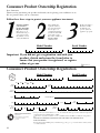
Product Registration
for Canadian Customers . . . . .43, 44
Product Registration
for U.S. Customers . . . . . . . . .41, 42
State of California Water
Treatment Device Certificate . . . . .48
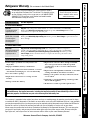
Warranty for Canadian
Customers . . . . . . . . . . . . . . . . . . .46
Warranty for U.S. Customers . . . . .45
Réfrigérateurs
Congélateur inférieur
Refrigeradores
Congelador inferior
Write the model and serial
numbers here:
Model #______________________
Serial # ______________________
Find these numbers on a label
on the right side, near the top of
the refrigerator compartment.
Models 21 and 25
Manuel d’utilisation
et d’installation
Owner’s Manual and
Installation Instructions
Manual del propietario
y instalación
La section française commence à la page 49
La sección en español empieza en la página 93

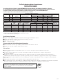
IMPORTANT SAFETY INFORMATION.
READ ALL INSTRUCTIONS BEFORE USING.
WARNING!
Use this appliance only for its intended purpose as described in this Owner’s Manual.
SAFETY PRECAUTIONS
When using electrical appliances, basic safety precautions should be followed, including the following:
■
■ This refrigerator must be properly installed
and located in accordance with the Installation
Instructions before it is used.
■
■ Do not allow children to climb, stand or hang
on the shelves in the refrigerator. They could
damage the refrigerator and seriously injure
themselves.
■
■ Do not touch the cold surfaces in the freezer
compartment when hands are damp or wet.
Skin may stick to these extremely cold surfaces.
■
■ Do not store or use gasoline or other flammable
vapors and liquids in the vicinity of this or any
other appliance.
■
■ Keep fingers out of the “pinch point” areas;
clearances between the doors and between
the doors and cabinet are necessarily small.
Be careful closing doors when children are
in the area.
■
■ In refrigerators with automatic icemakers,
avoid contact with the moving parts of the
ejector mechanism, or with the heating element
that releases the cubes. Do not place fingers or
hands on the automatic icemaking mechanism
while the refrigerator is plugged in.
■
■ Unplug the refrigerator before cleaning and
making repairs.
NOTE: We strongly recommend that any servicing be
performed by a qualified individual.
■
■ Setting either or both controls to 0 (off) does
not remove power to the light circuit.
■
■ Do not refreeze frozen foods which have
thawed completely.
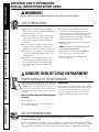
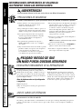
PROPER DISPOSAL OF THE REFRIGERATOR
Child entrapment and suffocation are not problems
of the past. Junked or abandoned refrigerators are
still dangerous…even if they will sit for “just a few
days.” If you are getting rid of your old refrigerator,
please follow the instructions below to help prevent
accidents.
Before You Throw Away Your Old Refrigerator
or Freezer:
■ Take off the doors.
■ Leave the shelves in place so that children may
not easily climb inside.
Refrigerants
All refrigeration products contain refrigerants,
which under federal law must be removed prior
to product disposal. If you are getting rid of
an old refrigeration product, check with the
company handling the disposal about what
to do.
USE OF EXTENSION CORDS
Because of potential safety hazards under certain conditions, we strongly recommend against
the use of an extension cord.
However, if you must use an extension cord, it is absolutely necessary that it be a UL-listed (in the United
States) or a CSA certified (in Canada), 3-wire grounding type appliance extension cord having a grounding
type plug and outlet and that the electrical rating of the cord be 15 amperes (minimum) and 120 volts.
DANGER! RISK OF CHILD ENTRAPMENT
Consumer Support Troubleshooting Tips
Operating Instructions Safety InstructionsInstallation Instructions
2

3
Consumer SupportTroubleshooting TipsOperating InstructionsSafety Instructions Installation Instructions
ge.com
WARNING!
HOW TO CONNECT ELECTRICITY
Do not, under any circumstances, cut or remove the third (ground) prong from the power cord.
For personal safety, this appliance must be properly grounded.
The power cord of this appliance is equipped
with a 3-prong (grounding) plug which mates
with a standard 3-prong (grounding) wall outlet to
minimize the possibility of electric shock hazard
from this appliance.
Have the wall outlet and circuit checked by a
qualified electrician to make sure the outlet is
properly grounded.
Where a standard 2-prong wall outlet is
encountered, it is your personal responsibility and
obligation to have it replaced with a properly
grounded 3-prong wall outlet.
The refrigerator should always be plugged into its
own individual electrical outlet which has a voltage
rating that matches the rating plate.
This provides the best performance and also
prevents overloading house wiring circuits which
could cause a fire hazard from overheated wires.
Never unplug your refrigerator by pulling on the
power cord. Always grip plug firmly and pull
straight out from the outlet.
Repair or replace immediately all power cords that
have become frayed or otherwise damaged. Do not
use a cord that shows cracks or abrasion damage
along its length or at either end.
When moving the refrigerator away from the
wall, be careful not to roll over or damage the
power cord.
READ AND FOLLOW THIS SAFETY INFORMATION CAREFULLY.
SAVE THESE INSTRUCTIONS

4
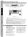
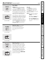
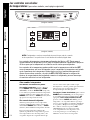
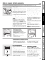
About the controls with temperature settings.
The temperature controls are preset in the factory at 37°F for the refrigerator compartment
and 0°F for the freezer compartment. Allow 24 hours for the temperature to stabilize to the
preset recommended settings.
The temperature controls can display both the SET temperature as well as the actual
temperature in the refrigerator and freezer. The actual temperature may vary slightly from
the SET temperature based on usage and operating environment.
Setting either or both controls to OFF stops cooling in both the freezer and refrigerator
compartments, but does not shut off electrical power to the refrigerator.
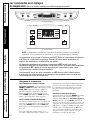
For Controls-on-the-Door Models:
To change the temperature, press and release the
WARMER or COLDER pad. The ACTUAL TEMP light
will come on and the display will show the actual
temperature. To change the temperature, tap
either the WARMER or COLDER pad until the
desired temperature is displayed.
For Controls Inside the Refrigerator:
Opening the door displays the actual temperature.
To change the temperature, press either the
WARMER or COLDER touch pads until the
desired temperature is displayed.
Once the desired temperature has been set,
the temperature display will return to the actual
refrigerator and freezer temperatures after 5
seconds. Several adjustments may be required.
Each time you adjust controls, allow 24 hours for the
refrigerator to reach the temperature you have set.
To turn the cooling system off, tap the WARMER pad
for either the refrigerator or the freezer until the
display shows OFF. To turn the unit back on, press the
COLDER pad for either the refrigerator or freezer.
Then press the COLDER pad again and it will go to
the preset points of 0°F for the freezer and 37°F for
the refrigerator. Setting either or both controls
to OFF stops cooling in both the freezer and
refrigerator compartments, but does not shut
off electrical power to the refrigerator.
Changing the Temperature
NOTE: The refrigerator is shipped with protective film covering the temperature controls.
If this film was not removed during installation, remove it now.
Consumer Support Troubleshooting Tips
Operating Instructions Safety InstructionsInstallation Instructions
(on some models)
(on some models)

Consumer SupportTroubleshooting TipsOperating Instructions
Safety Instructions
Installation Instructions
5
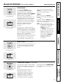
About TurboCool.
™
(on some models) ge.com
How it Works
TurboCool rapidly cools the refrigerator
compartment in order to more quickly
cool foods. Use TurboCool when adding a
large amount of food to the refrigerator
compartment, putting away foods after they
have been sitting out at room temperature
or when putting away warm leftovers. It can
also be used if the refrigerator has been
without power for an extended period.
Once activated, the compressor will turn on
immediately and the fans will cycle on and
off at high speed as needed for eight hours.
The compressor will continue to run until
the refrigerator compartment cools to
approximately 34°F (1°C), then it will cycle
on and off to maintain this setting. After 8
hours, or if TurboCool is pressed again, the
refrigerator compartment will return to
the original setting.
How to Use
Press TurboCool. The refrigerator
temperature display will show .
After TurboCool is complete, the
refrigerator compartment will return
to the original setting.
NOTES: The refrigerator temperature
cannot be changed during
TurboCool.
The freezer temperature is not
affected during TurboCool.
When opening the refrigerator
door during TurboCool, the fans
will continue to run if they have
cycled on.
About Door Alarm (on some models)
The door alarm will sound if any
door is open for more than 2 minutes.
The beeping stops when you close
the door.
(on some models)
(on some models)
(on some models)
(on some models)
About Energy Saver (on some models)
This product is equipped with an Energy
Saver feature. The refrigerator is shipped
with the Energy Saver feature enabled.
Over time, moisture can form on the front
surface of the refrigerator cabinet and
cause rust. If moisture does appear on the
front surface of the refrigerator cabinet,
turn off the Energy Saver feature by
pressing and releasing the ENERGY SAVER
pad on the control panel.
(on some models)
(on some models)

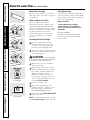
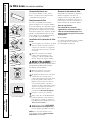
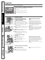
Water Filter Cartridge
The water filter cartridge is located in the
back upper right corner of the refrigerator
compartment.
When to Replace the Filter
There is a replacement indicator
light for the water filter cartridge on the
temperature display. This light will turn
orange to tell you that you need to replace
the filter soon. The filter cartridge should
be replaced when the replacement
indicator light turns red or if the flow
of water to the dispenser or icemaker
decreases.
Installing the Filter Cartridge
If you are replacing the cartridge,
first remove the old one. Open the
cartridge cover by pressing in on the
tab at the front and pulling down.
Remove the cartridge by slowly rotating
it counterclockwise. A small amount of
water may drip down.
CAUTION: If air has been trapped
in the system, the filter cartridge may be ejected as
it is removed. Use caution when removing.
Remove the protective foil from the
end of the cartridge.
Lining up the arrow on the cartridge
and the cartridge holder, slowly rotate
the cartridge clockwise until it stops.
When the cartridge is properly
installed, you will feel it “click” as it
locks into place. The grip on the end
of the cartridge should be positioned
vertically. Do not overtighten.
Close the cartridge cover.
Run water from the dispenser for
3 minutes (about 1
1
⁄2 gallons) to clear
the system and prevent sputtering.
See To Use the Dispenser section.
Press and hold the RESET WATER FILTER
pad for 3 seconds.
NOTE: A newly-installed water filter cartridge
may cause water to spurt from the dispenser.
Filter Bypass Plug
You must use the filter bypass plug when a
replacement filter cartridge is not available.
The icemaker will not operate without the
filter or filter bypass plug.
Replacement Filters:
To order additional filter cartridges
in the United States, visit our Website,
ge.com, or call GE Parts and Accessories,
800.626.2002.
Filter Model GSWF
Customers in Canada should consult
the yellow pages for the nearest Mabe
Service Center.
About the water filter. (on some models)
Consumer Support Troubleshooting Tips
Operating Instructions Safety InstructionsInstallation Instructions
6
(on some models)
(on some models)

7
Consumer SupportTroubleshooting TipsOperating InstructionsSafety Instructions Installation Instructions
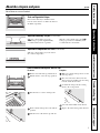
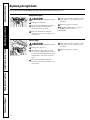
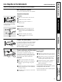
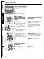
Rearranging the Shelves
To remove:
Remove all items from the shelf.
Tilt the shelf up at the front.
Lift the shelf up at the back and
bring the shelf out.
To replace:
While tilting the shelf up, insert the top
hook at the back of the shelf in a slot
on the track.
Lower the front of the shelf until the
bottom of the shelf locks into place.
Spillproof Shelves (on some models)
Spillproof shelves have special edges to
help prevent spills from dripping to lower
shelves. To remove or replace the shelves,
see Rearranging the Shelves.
About the shelves and bins. ge.com
Not all features are on all models.
Some models have wire shelves that
can be adjusted in the same manner.
Shelves in the refrigerator compartment are adjustable.
Refrigerator Compartment
Slide-Out Spillproof Shelf (on some models)
The slide-out spillproof shelf allows you
to reach items stored behind others. The
special edges are designed to help prevent
spills from dripping to lower shelves.
To remove:
Remove all items from shelf.
Slide the shelf out until it stops.
Lift the front edge of the shelf until the
central tabs are above the front bar.
Continue pulling the shelf forward
until it can be removed.
To replace:
Place the rear shelf tabs just in front of
the central notches on the shelf frame.
Slide the shelf in until the central tabs
are slightly behind the front bar.
Lower the shelf into place until it is
horizontal and slide the shelf in.
Make sure that the shelf sits flat after reinstallation
and doesn’t move freely from side to side.
Make sure you push the shelves all the way in
before you close the door.

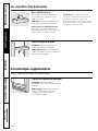
Non-Adjustable Bins on the Door
To remove: Lift the bin straight up, then
pull out.
To replace: Engage the bin in the molded
supports on the door and push down.
It will lock in place.
Adjustable Bins on the Door
Adjustable bins can easily be carried from
refrigerator to work area.
To remove: Lift bin straight up, then
pull out.
To replace or relocate: Slide in the bin just
above the molded door supports, and push
down. The bin will lock in place.
The snugger helps prevent tipping, spilling
or sliding of small items stored on the door
shelf. Grip the finger hold near the rear of
the snugger and move it to fit your needs.
About the additional features.
Not all features are on all models.
Non-Adjustable Beverage Rack
To remove: Lift the rack straight up, then
pull out.
To replace: Engage the rack in the molded
supports on the door and push down.
It will lock in place.
About the shelves and bins.
Consumer Support Troubleshooting Tips
Operating Instructions Safety InstructionsInstallation Instructions
8

9
Consumer SupportTroubleshooting TipsOperating Instructions
Safety Instructions
Installation Instructions
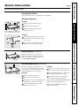
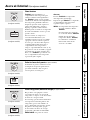
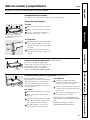
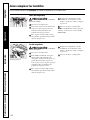
About the crispers and pans. ge.com
Not all features are on all models.
Fruit and Vegetable Crisper
Excess water that may accumulate in the
bottom of the drawers or under the drawers
should be wiped dry.
Adjustable Humidity Crisper (on some models)
Slide the control all the way to the
HIGH setting to provide high humidity
recommended for most vegetables.
Slide the control all the way to the LOW
setting to provide lower humidity levels
recommended for most fruits.
Adjustable Temperature Deli Pan (on some models)
Slide the control all the way to the left for
the coldest temperature.
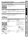
To remove:
Remove the fruit and vegetable drawers.
Pull the drawer out to the stop position.
Lift the lid to access the 4 swing locks.
Rotate all four swing locks to the unlock
position.
Lift the front of the drawer up and out.
To replace:
Make sure all four swing locks are in the
unlock position.
Place the sides of the drawer into the
drawer supports, making sure the swing
locks fit on the drawer slots.
Lock all four swing locks by rotating
them to the lock position.
Lower the lid and slide in the drawer.
Replace the fruit and vegetable drawers.
How to Remove and Replace the Deli Pan
Swing Locks

10
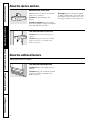
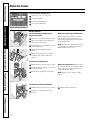
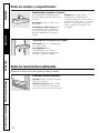
Freezer Shelves and Baskets
A shelf above the ice storage bin
A half-width basket
A shallow full-width basket
A deep full-width basket
Basket Removal
To remove the shallow full-width basket:
Pull the basket out to the stop location.
Lift the front up and over the stop
location.
Lift the basket up and out.
To remove the deep full-width basket on
freezer drawer models:
Open the freezer drawer until it stops.
The freezer basket rests on the inside
tabs on the drawer slides.
Lift the basket so that all 4 tabs are out
of the slide bracket.
Tilt the basket and lift out of the
drawer.
Make sure the plastic sleeves remain
attached to the 4 tabs on the slide
brackets.
When replacing the deep full-width basket:
Tilt the basket back and lower it down
into the drawer. Rotate the basket to a
horizontal position and press it down into
the 4 alignment tabs.
NOTE: Always be sure that all 4 basket tabs
are engaged in the slide brackets before
sliding back into the freezer.
To remove the half-width basket:
Pull the basket out to the stop location.
Lift the basket up at the front to release
it from the slides.
Lift the back up and out of the slide.
When replacing the basket, make sure that
the wire tabs and wire hooks on the sides
of the basket go into the slots in the top
of the upper basket slides.
NOTE: Always be sure to fully close this
basket.
About the freezer.
Not all features are on all models.
Appearance and features may vary
Appearance may vary
Appearance may vary
Appearance may vary
Tab
Consumer Support
Troubleshooting Tips Operating Instructions Safety InstructionsInstallation Instructions

Consumer SupportTroubleshooting TipsOperating Instructions
Safety Instructions
Installation Instructions
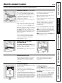
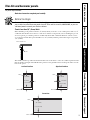
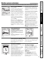
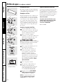
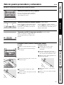
About the automatic icemaker. ge.com
Automatic Icemaker (on some models)
The icemaker will produce seven cubes
per cycle—approximately 100–130 cubes
in a 24-hour period, depending on freezer
compartment temperature, room
temperature, number of door openings
and other use conditions.
See below for how to access ice and reach
the power switch.
If the refrigerator is operated before the
water connection is made to the icemaker,
set the power switch in the O (off) position.
When the refrigerator has been connected
to the water supply, set the power switch to
the l (on) position. The icemaker power
light will turn green when the freezer light
switch is pressed in or when the freezer
door is closed.
The icemaker will fill with water when it
cools to 15°F (–10°C). A newly installed
refrigerator may take 12 to 24 hours to
begin making ice cubes.
You will hear a buzzing sound each time
the icemaker fills with water.
Throw away the first few batches of ice to
allow the water line to clear.
Be sure nothing interferes with the sweep
of the feeler arm.
When the bin fills to the level of the feeler
arm, the icemaker will stop producing
ice. It is normal for several cubes to be
joined together.
If ice is not used frequently, old ice cubes
will become cloudy, taste stale and shrink.
NOTE: In homes with lower-than-average water
pressure, you may hear the icemaker cycle multiple
times when making one batch of ice.
NOTE: Set the power switch to the O (off) position
if the water supply is shut off.
A newly installed refrigerator may take 12 to 24 hours to begin making ice.
Icemaker
Feeler Arm
Power
Switch
Green
Power Light
Accessing Ice and Reaching
the Power Switch
To reach the icemaker power switch, pull the
shelf above the ice bin straight out. Always
be sure to replace the shelf.
To access ice, simply pull the bin forward.
To access ice.
Shelf
Ice Bin
To reach the power switch.
Shelf
Ice Bin
Icemaker Accessory Kit
If your refrigerator did not come already
equipped with an automatic icemaker,
an icemaker accessory kit is available at
extra cost.
Check the back of the refrigerator for
the specific icemaker kit needed for
your model.
To Use the Dispenser
Press the glass gently against the top of the
dispenser cradle.
The spill shelf is not self-draining. To
reduce water spotting, the shelf should be
cleaned regularly.
If no water is dispensed when the refrigerator is first
installed, there may be air in the water line system.
Press the dispenser arm for at least two minutes to
remove trapped air from the water line and to fill the
water system. To flush out impurities in the water
line, throw away the first six glassfuls of water.
Locking the Dispenser
Press the LOCK pad for 3 seconds to lock
the dispenser and control panel. To unlock,
press and hold the pad again for 3 seconds.
Door Alarm
To set the alarm, press the DOOR ALARM
pad. The indicator light will illuminate.
This alarm will sound if either door is
open for more than 2 minutes. The
beeping stops when you close the door.
Spill Shelf
11
Dispenser Cradle

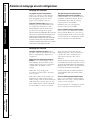
Care and cleaning of the refrigerator.
Cleaning the Outside
The door handles and trim. Clean with a cloth
dampened with soapy water. Dry with a soft
cloth. Do not use wax on the door handles
and trim.
Keep the outside clean. Wipe with a clean
cloth lightly dampened with kitchen
appliance wax or mild liquid dish
detergent. Dry and polish with a clean,
soft cloth.
Do not wipe the refrigerator with a soiled dish
cloth or wet towel. These may leave a residue
that can erode the paint. Do not use scouring
pads, powdered cleaners, bleach or cleaners
containing bleach because these products can
scratch and weaken the paint finish.
The stainless steel panels and door handles.
Stainless steel (on some models) can be
cleaned with a commercially available
stainless steel cleaner. A spray-on stainless
steel cleaner works best.
Do not use appliance wax or polish
on the stainless steel.
Silver-plated plastic parts. Wash parts with
soap or other mild detergents. Wipe clean
with a sponge, damp cloth or paper towel.
Do not scrub with steel-wool pads or other
abrasive cleaners.
Cleaning the Inside
To help prevent odors, leave an open box of
baking soda in the refrigerator and freezer
compartments.
Unplug the refrigerator before cleaning. If this
is not practical, wring excess moisture out
of sponge or cloth when cleaning around
switches, lights or controls.
Use an appliance wax polish on the inside
surface between the doors.
Use warm water and baking soda solution—
about a tablespoon (15 ml) of baking soda
to a quart (1 liter) of water. This both cleans
and neutralizes odors. Rinse and wipe dry.
After cleaning the door gaskets, apply a
thin layer of petroleum jelly to the door
gaskets at the hinge side. This helps keep
the gaskets from sticking and bending out
of shape.
Avoid cleaning cold glass shelves with hot water
because the extreme temperature difference may
cause them to break. Handle glass shelves
carefully. Bumping tempered glass can cause
it to shatter.
Do not wash any plastic refrigerator parts in
the dishwasher.
Silver-accented plastic parts. Wash parts
with soapy water. Wipe clean with a sponge,
damp cloth or paper towel.
Do not scrub with steel-wool pads or other
abrasive cleaners.
12
Consumer Support Troubleshooting Tips
Operating Instructions Safety InstructionsInstallation Instructions

Consumer SupportTroubleshooting TipsOperating Instructions
Safety Instructions
Installation Instructions
13
For long vacations or absences, remove
food and unplug the refrigerator. Clean the
interior with a baking soda solution of one
tablespoon (15 ml) of baking soda to one
quart (1 liter) of water. Leave the doors
open.
Set the icemaker power switch to the O (off)
position and shut off the water supply to
the refrigerator.
If the temperature can drop below
freezing, have a qualified servicer drain the
water supply system (on some models) to
prevent serious property damage due to
flooding.
ge.com
Behind the Refrigerator
Be careful when moving the refrigerator
away from the wall. All types of floor
coverings can be damaged, particularly
cushioned coverings and those with
embossed surfaces.
Raise the leveling legs located at the
bottom front of the refrigerator.
Pull the refrigerator straight out and return
it to position by pushing it straight in.
Moving the refrigerator in a side direction
may result in damage to the floor covering
or refrigerator.
Lower the leveling legs until they touch
the floor.
When pushing the refrigerator back, make sure
you don’t roll over the power cord or icemaker
supply line (on some models) and ensure the
anti-tip bracket is engaged (if equipped).
Preparing for Vacation
Preparing to Move
Secure all loose items such as base grille,
shelves and drawers by taping them
securely in place to prevent damage.
When using a hand truck to move the
refrigerator, do not rest the front or back
of the refrigerator against the hand truck.
This could damage the refrigerator. Handle
only from the sides of the refrigerator.
Be sure the refrigerator stays in an upright
position during moving.

14
Consumer Support Troubleshooting Tips
Operating Instructions Safety InstructionsInstallation Instructions
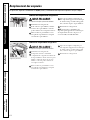
Refrigerator Lights
CAUTION: Light bulbs may be hot.
Unplug the refrigerator.
To remove the light shield, grasp the
shield at the back and pull out to
release the tabs at the back.
Rotate the shield down and then
forward to release the tabs at the front
of the shield.
After replacing with an appliance bulb
of the same or lower wattage, replace
the shield.
Plug the refrigerator back in.
NOTE: Appliance bulbs may be ordered
from GE Parts and Accessories,
800.626.2002.
Freezer Light
Replacing the light bulbs.
Turning the control to the 0 (off) position does not remove power to the light circuit.
Appearance may vary
CAUTION: Light bulbs may be hot.
Unplug the refrigerator.
The bulb is located at the top of the
freezer inside a light shield. To remove
the shield, grasp the shield at the back
and pull out to release the tabs at the
back.
Rotate the shield down and then
forward to release the tabs at the front
of the shield.
After replacing with an appliance bulb
of the same or lower wattage, replace
the shield.
Plug the refrigerator back in.

15
Consumer SupportTroubleshooting TipsOperating Instructions
Safety Instructions
Installation Instructions
Trim kits and decorator panels.
Read these instructions completely and carefully.
Before You Begin
Some models are equipped with trim kits that allow you to install door panels. You can order
pre-cut black or white decorator panels from GE Parts and Accessories, 800.626.2002, or you can
add wood panels to match your kitchen cabinets.
Panels less than 1/4″ (6 mm) thick
When installing wood panels less than 1/4″ (6 mm) thick, you need to create a filler panel, such as 1/8″
cardboard, that will fit between the face of the door and the wood panel. If you are installing the pre-cut
decorator panels, pre-cut filler panels are included in the kit. The combined thickness of the decorator
or wood panel and the filler panel should be 11/32″ (8.7 mm) with the panel itself being no larger than
1/4″ (6 mm).
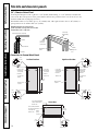
For panel required models
Panels 1/4″ thick or less
1/4″ max
The handle and the top and bottom trim stand in front of the surface of the door, which requires that the
filler be smaller in length and width than the panel. Use the guidelines below and tape the filler onto the
back of the panel.
Left Fresh Food Door
Freezer Door
Filler
2 1/2″ (63.5 mm)
3/4″ (19 mm)
3/4″ (19 mm)
Panel
Filler
2 1/2″ (63.5 mm)
3/4″ (19 mm)
Panel
Right Fresh Food Door
Filler
2 1/2″ (63.5 mm)
3/4″ (19 mm)
3/4″ (19 mm)
Panel

Consumer Support
Troubleshooting Tips
Operating Instructions Safety InstructionsInstallation Instructions
16
Trim kits and decorator panels.
Dimensions for Custom Wood Panels
3/4″ (19 mm) or Raised Panel
A raised panel design screwed or glued to a 1/4″ (6 mm) thick backing, or a 3/4″ (19 mm) routed board
can be used. The raised portion of the panel must be fabricated to permit clearances of at least 2″ (5.1 cm)
from the handle side for fingertip clearance.
Panels thicker than 1/4″ (6 mm), up to 3/4″ (19 mm) max., will require that the outer 5/16″ (8 mm) of
panel perimeter be no thicker than 1/4″ (6 mm).
Weight limitations for custom panels:
Fresh Food 10 lbs. (4.5 kg) max. for each door
Freezer Door 18 lbs. (8 kg) max.
2″ (5.1 cm)
Clearance
Handle Side
Appearance
Panel
Refrigerator
Door
1/4″ (6 mm)
Thick Backing
3/4″
(19 mm)
Panels thicker than 1/4″ (6 mm)
1/4″ (6 mm) max
3/4″ (19 mm)
5/16″ (8 mm)
Right Fresh Food Door
Freezer Door
Top, right and
bottom
16 29/32″ (42.9 cm)
5/16″ (8 mm)
minimum at
1/4″ (6 mm)
thickness
Raised portion
of panel
2″ (51 mm)
minimum at
1/4″ (6 mm)
thickness
Handle side
26 3/32″
(66.3 cm)
2″ (51 mm) minimum at
1/4″ (6 mm) thickness
Handle side
Left, right and
bottom sides
5/16″ (8 mm) minimum
at 1/4″ (6 mm) thickness
35 29/32″ (91.2 cm)
Raised
portion
of panel
38 15/16″
(98.9 cm)
Left Fresh Food Door
Top, left and
bottom
16 29/32″ (42.9 cm)
5/16″ (8 mm)
minimum at
1/4″ (6 mm)
thickness
Raised portion
of panel
2″ (51 mm)
minimum at
1/4″ (6 mm)
thickness
Handle side
38 15/16″
(98.9 cm)
1/8″
(3 mm)
1/8″
(3 mm)
1/8″
(3 mm)
1/8″
(3 mm)
1/8″
(3 mm)
1/4″
(6 mm)
1/4″
(6 mm)
1/4″
(6 mm)
1/4″
(6 mm)
1/4″
(6 mm)
1/8″
(3 mm)
1/4″
(6 mm)

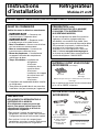
Installation
Refrigerator
Instructions
Models 21 and 25
Questions? Call 800.GE.CARES (800.432.2737) or Visit our Website at: ge.com
In Canada, call 1.800.561.3344 or Visit our Website at: www.geappliances.ca
BEFORE YOU BEGIN
Read these instructions completely and carefully.
•
IMPORTANT — Save these instructions for
local inspector’s use.
•
IMPORTANT — Observe all governing
codes and ordinances.
• Note to Installer – Be sure to leave these
instructions with the Consumer.
• Note to Consumer – Keep these instructions for
future reference.
• Skill level – Installation of this appliance requires
basic mechanical skills.
• Completion time – Refrigerator Installation
20 minutes
Water Line Installation
30 minutes
Anti-Tip Bracket Installation
20 minutes
• Proper installation is the responsibility of the
installer.
• Product failure due to improper installation is not
covered under the Warranty.
PREPARATION
MOVING THE REFRIGERATOR INDOORS
If the refrigerator will not fit through a doorway, the
refrigerator door and freezer drawer can be removed.
• To remove the refrigerator door, see Step 1 in the
Reversing the Door Swing section.
• To remove the freezer drawer, see the Removing
the Freezer Drawer section.
WATER SUPPLY TO THE ICEMAKER AND
DISPENSER (ON SOME MODELS)
If the refrigerator has an icemaker, it will have
to be connected to a cold water line. A GE water
supply kit (containing tubing, shutoff valve, fittings
and instructions) is available at extra cost from
your dealer, by visiting our Website at ge.com (in
Canada at www.geappliances.ca) or from Parts and
Accessories, 800.626.2002 (In Canada 1.888.261.3055).
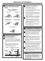
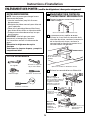
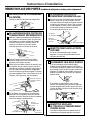
TOOLS YOU MAY NEED
Adjustable Wrench
1/4″ Outer Diameter
Compression Nut
and Ferrule (sleeve)
(icemaker models only)
Phillips Head Screwdriver
17
3/8″ and 5/16″ Socket
Ratchet/Driver
3/32″, 1/8″ and 1/4″ Allen
wrenches
MATERIALS YOU MAY NEED (not included)
Pencil
1/8″ Drill Bit and
Electric or Hand Drill
Tape measure
1/4″ Nut Driver
Lag Bolts
Anchor Sleeves
For Anti-Tip Bracket Mounted on CONCRETE Floors Only
Drill Bit Appropriate for Anchors
Wire Cutters
Level

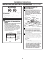
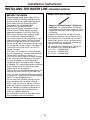
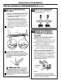
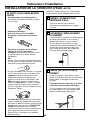
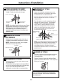
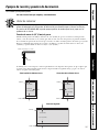
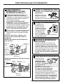
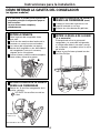
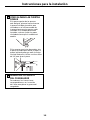
LOCATING THE ANTI-TIP
FLOOR BRACKET
Place the anti-tip floor bracket locator
template (included inside the anti-tip kit)
onto the floor up against the rear wall,
within W, and in line with the desired
location of the RH side of the refrigerator
(see Figure 1).
Place the anti-tip floor bracket onto the
locator template with its RH floor holes
lined up with the floor holes indicated
on the template sheet, approximately 7
1
⁄4”
from the edge of the sheet or the RH side
of the refrigerator.
Hold down in position and use the anti-tip
floor bracket as a template for marking
the holes based upon your configuration
and type of construction as shown in Step
3. Mark the hole locations with a pencil,
nail or awl.
NOTE:
• It is REQUIRED to use at least 2 screws
to mount the floor bracket (one on each
side of the anti-tip floor bracket). Both
must be into either the wall or the floor.
Figure 2 indicates all the acceptable
mounting configurations for screws.
Identify the screw holes on the anti-tip
floor bracket for your configuration.
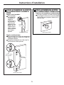
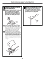
MEASURE CABINET OPENING
AVAILABLE VS. REFRIGERATOR
WIDTH
Measure width of cabinet opening where
refrigerator will be placed, W.
Be sure to account for any countertop
overhang, baseboard thickness and any
clearance desired. Width, W, should not
be less than 36 inches. The refrigerator
will be placed approximately in the
middle of this opening.
WARNING
Under certain circumstances, this refrigerator
can tip forward.
Injury to persons can result.
Install Anti-Tip Bracket packed with this
refrigerator.
1
Baseboard
Thickness
or Countertop
Overhang
(Whichever
Is Greater)
Plus Any
Desired
Clearance
Rear Wall
Front
RH Side
2
A
B
C
W
Base
Bracket
on the
Refrigerator
2 Wall Holes
RH Side of
Refrigerator
Floor – Concrete
(2 Holes)
Floor – Wood
(2 Holes)
7
1
⁄4
”
Locator
Template Sheet
Floor
Bracket
to Install
RH Holes
Rear RH
Corner of
Cabinet Wall
REFRIGERATOR
Figure 1 – Installation Overview
18
Installation Instructions
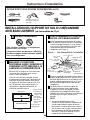
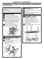
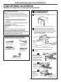
INSTALLING THE ANTI-TIP FLOOR BRACKET (on 21 ft. models)

Installation Instructions
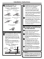
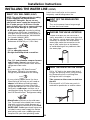
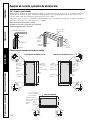
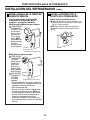
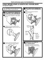
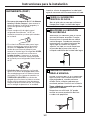
LOCATING THE ANTI-TIP
FLOOR BRACKET (cont.)
2
Preferred Installation –
Wood
Preferred Installation –
Concrete
Minimum Acceptable #1 –
Wall Plate Stud
Minimum Acceptable #2 –
Wood Floor
Minimum Acceptable #3 –
Concrete Floor
Figure 2 – Acceptable Screw
Placement Locations
CONCRETE Wall and Floor Construction:
• Anchors required (not provided):
4 each 1/4” x 1 1/2” lag bolts
4 each 1/2” O.D. sleeve anchors
• Drill the recommended size holes for
the anchors into the concrete at the
center of the holes marked in Step 2.
• Install the sleeve anchors into the drilled
holes. Place the anti-tip floor bracket as
indicated in Step 2. Remove the locator
template from the floor.
• Install the lag bolts through the anti-tip
floor bracket and tighten appropriately.
WOOD Wall and TILE Floor Construction:
• For this special case, locate the 2 wall
holes identified in Fig. 1. Drill an angled
1/8” pilot hole (approx. as shown in
Fig. 3) in the center of each hole.
• Mount the anti-tip floor bracket using
the Minimum Acceptable Installation #1,
as illustrated in Fig. 2.
C
B
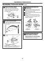
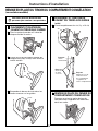
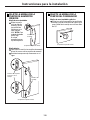
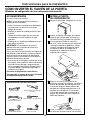
ANTI-TIP BRACKET INSTALLATION
WOOD Wall and Floor Construction:
• Drill the appropriate number of 1/8”
pilot holes in the center of each floor
bracket hole being used (a nail or awl
may be used if a drill is not available)
AND remove the locator template from
the floor.
• Mount the anti-tip floor bracket by
fastening the 2, or preferably 4, #10-16
hex-head screws tightly into place as
illustrated in Figure 3.
3
A
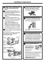
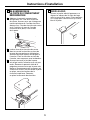
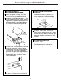
POSITIONING THE REFRIGERATOR
TO ENGAGE THE ANTI-TIP FLOOR
AND BASE BRACKETS
Before pushing the refrigerator into the
opening, plug the power cord into the
receptacle and connect waterline (if
equipped). Check for leaks.
Locate the refrigerator’s RH side and
move back approximately in line with the
RH side of the cabinet opening, W. This
should position the anti-tip floor bracket
to engage the anti-tip base bracket on the
refrigerator.
Gently roll the refrigerator back into
the cabinet opening until it comes
to a complete stop. Check to see if
the refrigerator front lines up with the
cabinet front face. If not, carefully rock
the refrigerator forward and backward
until engagement occurs and you notice
that the refrigerator is fully pushed up
against the rear wall.
OPTIONAL: Adjust the rear (and front)
wheel height settings to fully engage the
rear anti-tip brackets, while also aligning
the refrigerator front with the cabinet
front face.
4
A
C
B
D
Figure 3 – Attachment to
Wall and Floor
NOTE:
If you pull the refrigerator out and away from
the wall for any reason, make sure the anti-tip
floor bracket is engaged when the refrigerator
is pushed back against the rear wall.
Rear RH
Corner of the
Refrigerator
Floor
Wall
Plate
Stud
Floor
Bracket
2 Screws
Must Enter
Wood or
Metal Stud
Wall
19

Installation Instructions
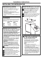
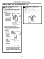
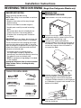
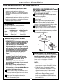
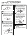
INSTALLING THE REFRIGERATOR
REFRIGERATOR LOCATION
• Do not install the refrigerator where the
temperature will go below 60°F (16°C) because it
will not run often enough to maintain proper
temperatures.
• Do not install the refrigerator where the
temperature will go above 100°F (37°C) because it
will not perform properly.
• Install it on a floor strong enough to support it fully
loaded.
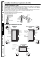
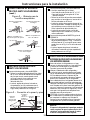
CLEARANCES
Allow the following clearances for ease of installation,
proper air circulation and plumbing and electrical
connections.
Standard Depth Counter Depth
Models Models
Sides 1/8″ (3 mm) 1/8″ (3 mm)
Top 1″ (25 mm) 1″ (25 mm)
Back 1″ (25 mm) 1/2″ (13 mm)
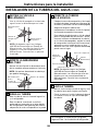
CONNECTING THE REFRIGERATOR
TO THE HOUSE WATER LINE
(icemaker and dispenser models)
A cold water supply is required for automatic
icemaker operation. If there is not a cold water
supply, you will need to provide one. See
Installing the Water Line section.
NOTES:
• Before making the connection to the
refrigerator, be sure the refrigerator power cord
is not plugged into the wall outlet.
• If your refrigerator does not have a water filter,
we recommend installing one if your water
supply has sand or particles that could clog the
screen of the refrigerator’s water valve. Install it
in the water line near the refrigerator. If using
GE SmartConnect
™
Refrigerator Tubing Kit, you
will need an additional tube (WX08X10002) to
connect the filter. Do not cut plastic tube to
install filter.
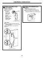
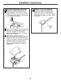
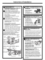
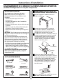
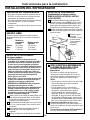
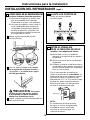
1
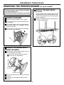
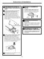
REMOVE TOP CAP
(on some models)
• IMPORTANT NOTE: This refrigerator is 34-1/2″ deep.
Doors and passageways leading to the installation
location must be at least 36″ wide in order to
leave the doors and handles attached to the
refrigerator while transporting it into the installation
location. If passageways are less than 36″, the
refrigerator doors and handles can easily be scratched
and damaged. The top cap and doors can be removed
to allow the refrigerator to be safely moved indoors.
Start with Step A.
• If it is not necessary to remove doors, skip Step A.
Leave tape and all packaging on doors until the
refrigerator is in the final location.
• SKID REMOVAL: Tilt refrigerator to each side to
remove skid.
• NOTE: Use a padded hand truck to move this
refrigerator. Place the refrigerator on the hand
truck with a side against the truck. We strongly
recommend that TWO PEOPLE move and complete
this installation.
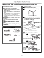
Locate and remove the two Phillips head screws
on the top of the refrigerator. Remove the two
screws on each side at the rear of the top cap.
Lift off and remove top cap.
Remove the fresh-food door. Refer to Steps 1
through 3 of “Reversing the Door Swing” section.
Remove the bottom freezer drawer. Refer to
“Removing Freezer Drawer” section.
Move refrigerator to the installation location.
A
B
C
D
20
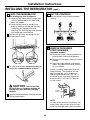
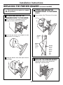
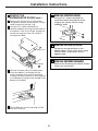
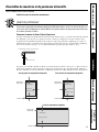
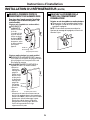
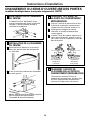
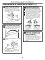
REMOVE TOP CAP (cont.) (on some models)
REINSTALL DOORS, DRAWERS AND TOP CAP
Carefully lower the door onto the center hinge.
Reinstall top hinge. NOTE: Ensure the door is
properly aligned to the case top to avoid
readjustment of the door during top cap
reinstallation.
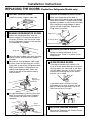
Place cap over the top of the refrigerator. Reinstall
the original screws in the top and back of the cap.
Reinstall the bottom freezer drawer. Refer to
“Replacing the Freezer Drawer” section.
E
F
G
A
Top Hinge B
Page is loading ...
Page is loading ...
Page is loading ...
Page is loading ...
Page is loading ...
Page is loading ...
Page is loading ...
Page is loading ...
Page is loading ...
Page is loading ...
Page is loading ...
Page is loading ...
Page is loading ...
Page is loading ...
Page is loading ...
Page is loading ...
Page is loading ...
Page is loading ...
Page is loading ...
Page is loading ...
Page is loading ...
Page is loading ...
Page is loading ...
Page is loading ...
Page is loading ...
Page is loading ...
Page is loading ...
Page is loading ...
Page is loading ...
Page is loading ...
Page is loading ...
Page is loading ...
Page is loading ...
Page is loading ...
Page is loading ...
Page is loading ...
Page is loading ...
Page is loading ...
Page is loading ...
Page is loading ...
Page is loading ...
Page is loading ...
Page is loading ...
Page is loading ...
Page is loading ...
Page is loading ...
Page is loading ...
Page is loading ...
Page is loading ...
Page is loading ...
Page is loading ...
Page is loading ...
Page is loading ...
Page is loading ...
Page is loading ...
Page is loading ...
Page is loading ...
Page is loading ...
Page is loading ...
Page is loading ...
Page is loading ...
Page is loading ...
Page is loading ...
Page is loading ...
Page is loading ...
Page is loading ...
Page is loading ...
Page is loading ...
Page is loading ...
Page is loading ...
Page is loading ...
Page is loading ...
Page is loading ...
Page is loading ...
Page is loading ...
Page is loading ...
Page is loading ...
Page is loading ...
Page is loading ...
Page is loading ...
Page is loading ...
Page is loading ...
Page is loading ...
Page is loading ...
Page is loading ...
Page is loading ...
Page is loading ...
Page is loading ...
Page is loading ...
Page is loading ...
Page is loading ...
Page is loading ...
Page is loading ...
Page is loading ...
Page is loading ...
Page is loading ...
Page is loading ...
Page is loading ...
Page is loading ...
Page is loading ...
Page is loading ...
Page is loading ...
Page is loading ...
Page is loading ...
Page is loading ...
Page is loading ...
Page is loading ...
Page is loading ...
Page is loading ...
Page is loading ...
Page is loading ...
Page is loading ...
Page is loading ...
Page is loading ...
Page is loading ...
Page is loading ...
Page is loading ...
Page is loading ...
Page is loading ...
Page is loading ...
-
 1
1
-
 2
2
-
 3
3
-
 4
4
-
 5
5
-
 6
6
-
 7
7
-
 8
8
-
 9
9
-
 10
10
-
 11
11
-
 12
12
-
 13
13
-
 14
14
-
 15
15
-
 16
16
-
 17
17
-
 18
18
-
 19
19
-
 20
20
-
 21
21
-
 22
22
-
 23
23
-
 24
24
-
 25
25
-
 26
26
-
 27
27
-
 28
28
-
 29
29
-
 30
30
-
 31
31
-
 32
32
-
 33
33
-
 34
34
-
 35
35
-
 36
36
-
 37
37
-
 38
38
-
 39
39
-
 40
40
-
 41
41
-
 42
42
-
 43
43
-
 44
44
-
 45
45
-
 46
46
-
 47
47
-
 48
48
-
 49
49
-
 50
50
-
 51
51
-
 52
52
-
 53
53
-
 54
54
-
 55
55
-
 56
56
-
 57
57
-
 58
58
-
 59
59
-
 60
60
-
 61
61
-
 62
62
-
 63
63
-
 64
64
-
 65
65
-
 66
66
-
 67
67
-
 68
68
-
 69
69
-
 70
70
-
 71
71
-
 72
72
-
 73
73
-
 74
74
-
 75
75
-
 76
76
-
 77
77
-
 78
78
-
 79
79
-
 80
80
-
 81
81
-
 82
82
-
 83
83
-
 84
84
-
 85
85
-
 86
86
-
 87
87
-
 88
88
-
 89
89
-
 90
90
-
 91
91
-
 92
92
-
 93
93
-
 94
94
-
 95
95
-
 96
96
-
 97
97
-
 98
98
-
 99
99
-
 100
100
-
 101
101
-
 102
102
-
 103
103
-
 104
104
-
 105
105
-
 106
106
-
 107
107
-
 108
108
-
 109
109
-
 110
110
-
 111
111
-
 112
112
-
 113
113
-
 114
114
-
 115
115
-
 116
116
-
 117
117
-
 118
118
-
 119
119
-
 120
120
-
 121
121
-
 122
122
-
 123
123
-
 124
124
-
 125
125
-
 126
126
-
 127
127
-
 128
128
-
 129
129
-
 130
130
-
 131
131
-
 132
132
-
 133
133
-
 134
134
-
 135
135
-
 136
136
-
 137
137
-
 138
138
-
 139
139
-
 140
140


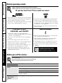
Ask a question and I''ll find the answer in the document
Finding information in a document is now easier with AI
in other languages
- français: GE PFSF5NJWCC Le manuel du propriétaire
- español: GE PFSF5NJWCC El manual del propietario
Related papers
-
GE Side-by-Side Stainless Steel Free-Standing Refrigerators User manual
-
GE GBSL0HCXLLS Owner's manual
-
GE Profile PDS20MFWWW Owner's manual
-
-
-
-
-
GE Profile PSS26LGSBB Owner's manual
-
-
Other documents
-
Groupe Brandt DRU104MU1 Owner's manual
-
Hotpoint 23 User manual
-
 GE Appliances GSS25GSHSS Owner's manual
-
 GE Appliances GNE21FMKES Installation guide
-
GE Appliances GNE21FMKES Owner's manual
-
 GE Monogram 20 User manual
-
Maytag MBR2556KES Owner's manual
-
Maytag MRT311FFFE User manual
-
Maytag MRT311FFFZ Owner's manual
-
AMERICANA Americana A3316ABS User manual


