Equip 5F-4DLX12 Installation guide

Category
Sanitary ware
Type
Installation guide

This manual is also suitable for

P/N: 098-013851-45 Rev.3
Date: 01-15-16
Drawn: TEH
Checked: DMH 02-09-16
Approved: JHB 02-23-16
Installation and
Installation and
Maintenance
Maintenance
Instructions
Instructions
Limited One Year Warranty
Equip warrants the original purchaser (other than
for purposes of resale) that such product is free from
defects in material and workmanship for a period
of one (1) year from the date of purchase. During
this warranty period, if the product is found to be
defective, equip shall, at its option, repair and/or
replace it. To obtain warranty service, products
must be returned to:
Equip Foodservice Accessories
Attn: Warranty Repair Department
P.O. Box 1088, 2 Saddleback Cove
Travelers Rest, SC 29690
Shipping, freight, insurance, and other
transportation charges of the product to equip and
the return of repaired or replaced product to the
purchaser are the responsibility of the purchaser.
Repair and/or replacement shall be made within
a reasonable time after receipt by Equip of the
returned product. This warranty does not cover
items which have received secondary finishing or
have been altered or modified after purchase, or
for defects caused by physical abuse to or misuse of
the product, or shipment of the products.
Any express warranty not provided herein, and
any remedy for Breach of Contract which might
arise, is hereby excluded and disclaimed. Any
implied warranties of merchantability or fitness
for a particular purpose are limited to one year in
duration. Under no circumstances shall Equip be
liable for loss of use or any special consequential
costs, expenses or damages.
Some states do not allow limitations on how
long an implied warranty lasts or the exclusion
or limitation of incidental or consequential
damages, so the above limitations or exclusions
may not apply to you. Specific rights under this
warranty and other rights vary from state to state.
Attention California Residents:
WARNING: This product contains chemicals
known to the State of California to cause cancer,
and birth defects or other reproductive harm.”
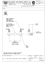
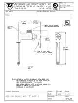
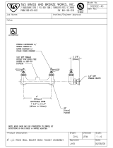
EQUIP 4” & 8”
DECK-MOUNT
FAUCETS AND
PRE-RINSE UNITS
Español:
Instrucciones de instalación y mantenimiento
Français:
Instructions pour l’installation et la maintenance
Deutsch:
Installations- und Wartungsanleitungen
中文:
安装与维护说明
2
Instructions
STEP 1
STEP 2
STEP 3
STEP 12
STEP 12
B-0425-M 1/2”
NPT Supply
Nipple Kit (2)
deck or
sink
3
Instructions
Note: If unit is equipped with a rigid or swivel spout/gooseneck, install spout/
gooseneck  rst.
Rigid Gooseneck Installation:
1. Apply Te on tape, Loctite, or pipe joint compound to threads of gooseneck.
Thread gooseneck into outlet hole of body until joint is secure and
gooseneck faces desired direction.
Swing Nozzle/ Swivel Gooseneck Installation:
Note: Silicon grease is applied to the interior swivel cavity of the body prior to
shipment. No additional grease is required.
2. Remove plastic cap from body outlet.
3. Insert nozzle/gooseneck into body cavity.
4. Tighten swivel lock nut using 1 5/16” wrench.
Faucet Body Installation:
5. Flush debris from water lines then shut o water supply.
6. Drill two holes, approximately 1” to 1 1/4” diameter, in deck or sink where
faucet body is to be installed. Holes must be 4” or 8” between centers, as
applicable.
7. Remove washers and nuts from B-0425-M supply nipple kits, or similar ½”
NPT inlets, and apply Te on tape or thread sealant to the threads on one
end of the nipples. Thread this end into the inlet hole of the faucet  ange
until the joints are secure.
8. Apply plumbers putty to faucet  ange mounting surfaces and insert the
supply nipples though the holes in the deck or sink.
9. Secure faucet in place with supply nipple kit washers and nuts.
10. Connect water supplies to nipples.
Pre-Rinse Installation:
11. After installation of the faucet body per steps 5 through 10, apply Te on
tape, Loctite, or pipe thread compound on the bottom of the riser. Slide
nger hook onto riser before riser installation. Thread riser into outlet
hole of faucet body until joint is secured.
12. Install wall bracket and  nger hook, tightening all fasteners securely.
13. Rotate spring and hose assembly until they face desired direction.
14. Turn on water supplies and check for leaks.
12
Equip Faucet and Pre-Rinse Unit Parts List
Ceramic Cartridge, Hot 013787-45
Ceramic Cartridge, Cold 013788-45
Handle Screw, Plain (10) 013849-45
Lever Handle Kit (includes color coded screws) 5-HDL-L
3/4-27 UN Full Flow Laminar Outlet 014250-45
3” Rigid Gooseneck w/ Laminar Outlet 5SP-03
Nut, Swivel 013839-25
O-Ring, Swivel Piece (10) 013848-45
5-1/2” Swivel Gooseneck w/ Laminar Outlet 5SP-05
6” Swing Nozzle w/ Laminar Outlet 5SP-06
8” Swing Nozzle w/ Laminar Outlet 5SP-08
10” Swing Nozzle w/ Laminar Outlet 5SP-10
12” Swing Nozzle w/ Laminar Outlet 5SP-12
14” Swing Nozzle w/ Laminar Outlet 5SP-14
16” Swing Nozzle w/ Laminar Outlet 5SP-16
18” Swing Nozzle w/ Laminar Outlet 5SP-18
Check Valve, 20mm 013840-45
Check Valve Adapter, 1/2” BSP 010321-45
Overhead Spring, PRU 014068-45
Finger Hook Assembly 004R
Spray Valve Assembly, PRU 5SV
Bonnet Valve Assembly, PRU 002856-40
Bumper, Spray Face & Screw for PRU 5SV-RK
Hose Assembly, 44” 5HSE44
Hose Assembly, 68” 5HSE68
Hose Assembly, 84” 5HSE84
Hose Assembly, 96” 5HSE96
1/2” NPT Supply Nipple Kit (2) B-0425-M
1/2” NPT Male Elbow Kit (2) B-0230-K
1/2” NPT Female Eccentric Flange 00AA
Wall Bracket Assembly, 6” 013716-40
Riser, 18” 000369-40
Part Numbers
  • Page 1 1
  • Page 2 2
  • Page 3 3
  • Page 4 4
  • Page 5 5
  • Page 6 6
  • Page 7 7
  • Page 8 8
  • Page 9 9
  • Page 10 10
  • Page 11 11
  • Page 12 12

Equip 5F-4DLX12 Installation guide

Category
Sanitary ware
Type
Installation guide
This manual is also suitable for

Ask a question and I''ll find the answer in the document

Finding information in a document is now easier with AI