36
Machine à glaçons modulaire - Fiche technique
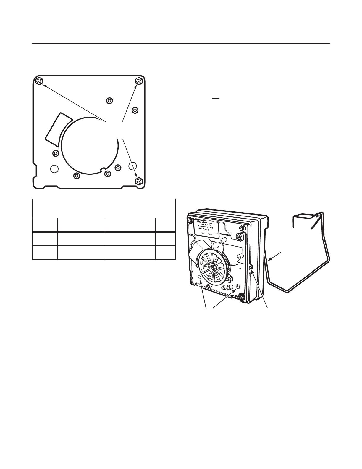
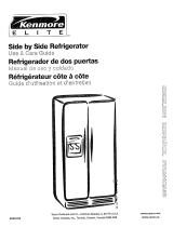
Points de test sur le module
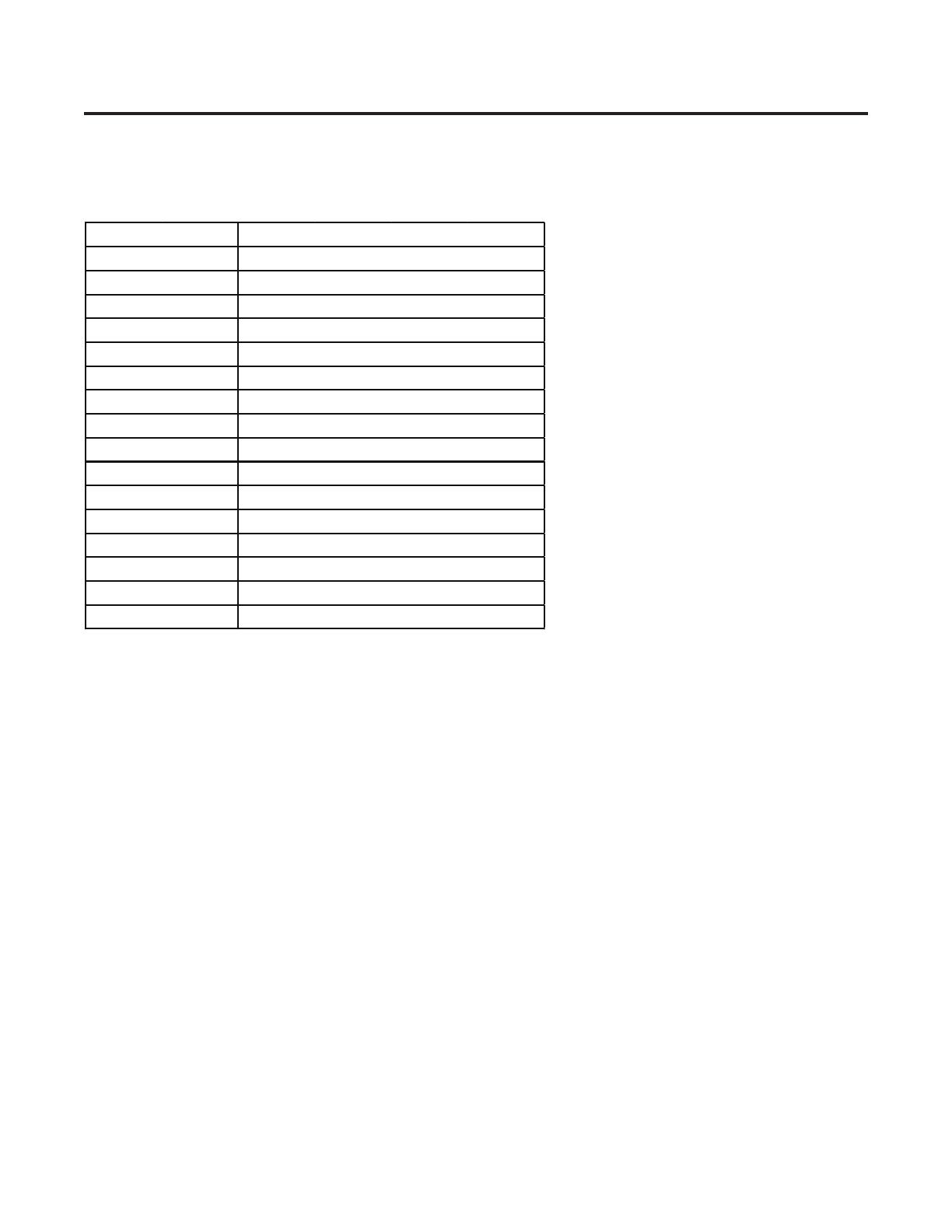
Spécifications
ÉLÉMENT CHAUFFANT DU MOULE – 185 WATTS, 72 OHMS
THERMOSTAT – FERMETURE À 17° ± 3 °
(BILAME) OUVERTURE À 32° ± 3°
REMPLISSAGE D'EAU – 140 CC, 7,5 S
MOTEUR – 1,5 WATT, 8800 OHMS
MODULE – CIRCUIT IMPRIMÉ,
CYCLE – UNE RÉVOLUTION
POUR MODÈLE 120 VOLTS
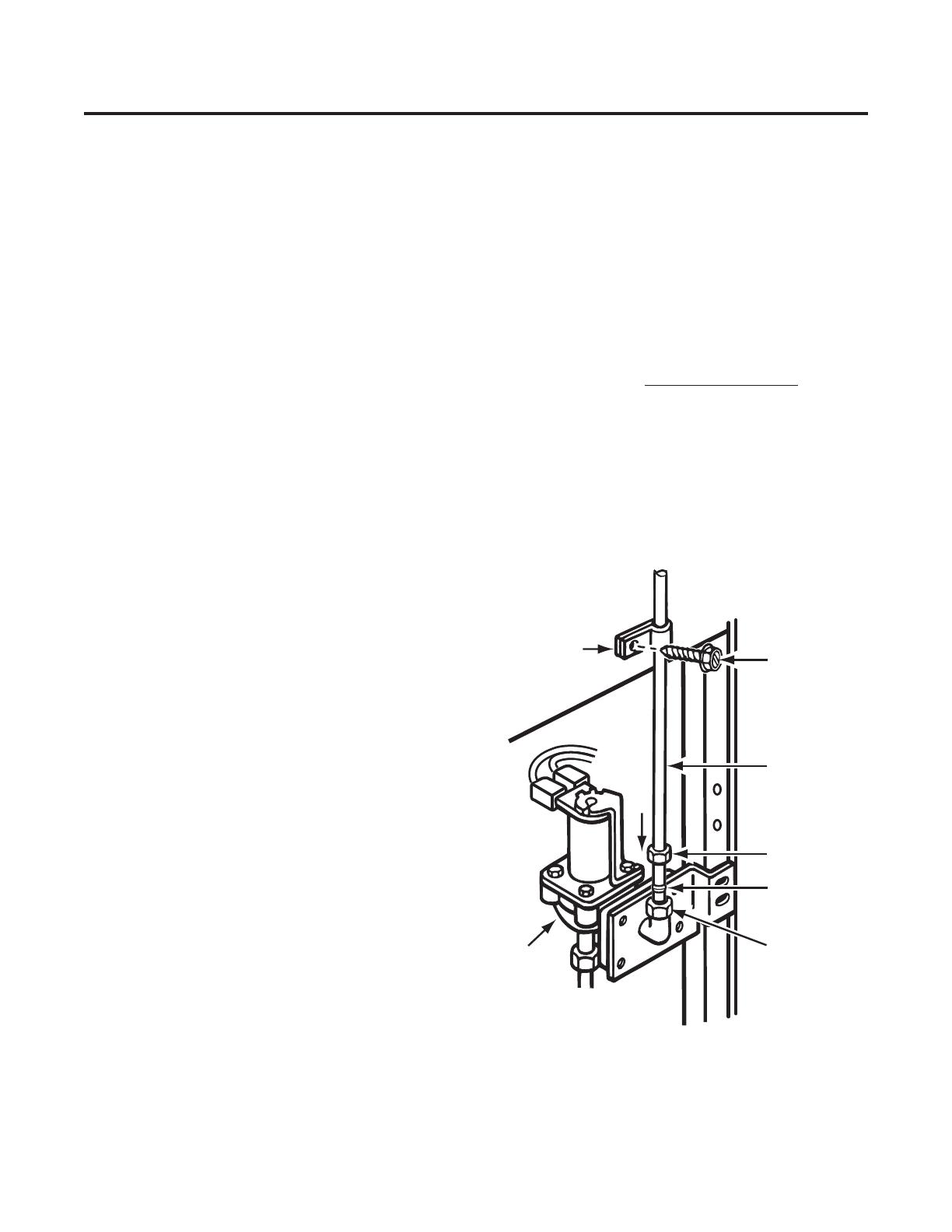
Opérations de dépannage
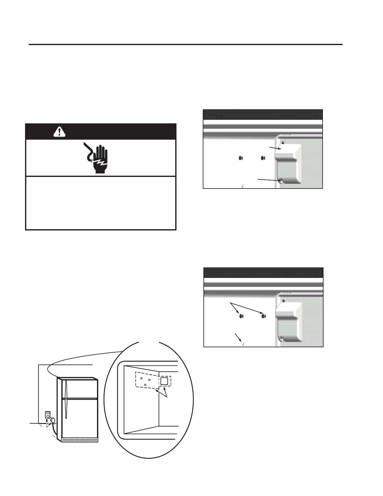
COUVERCLE
TIRER D'ABORD SUR LE BOUTON DE RÉGLAGE DU
DÉBIT D'EAU ET DÉBOÎTER LE COUVERCLE. FAIRE
TOURNER LE BOUTON (INDEXAGE) ET RÉINSTALLER
À LA MÊME POSITION POUR LE REMPLISSAGE D'EAU.
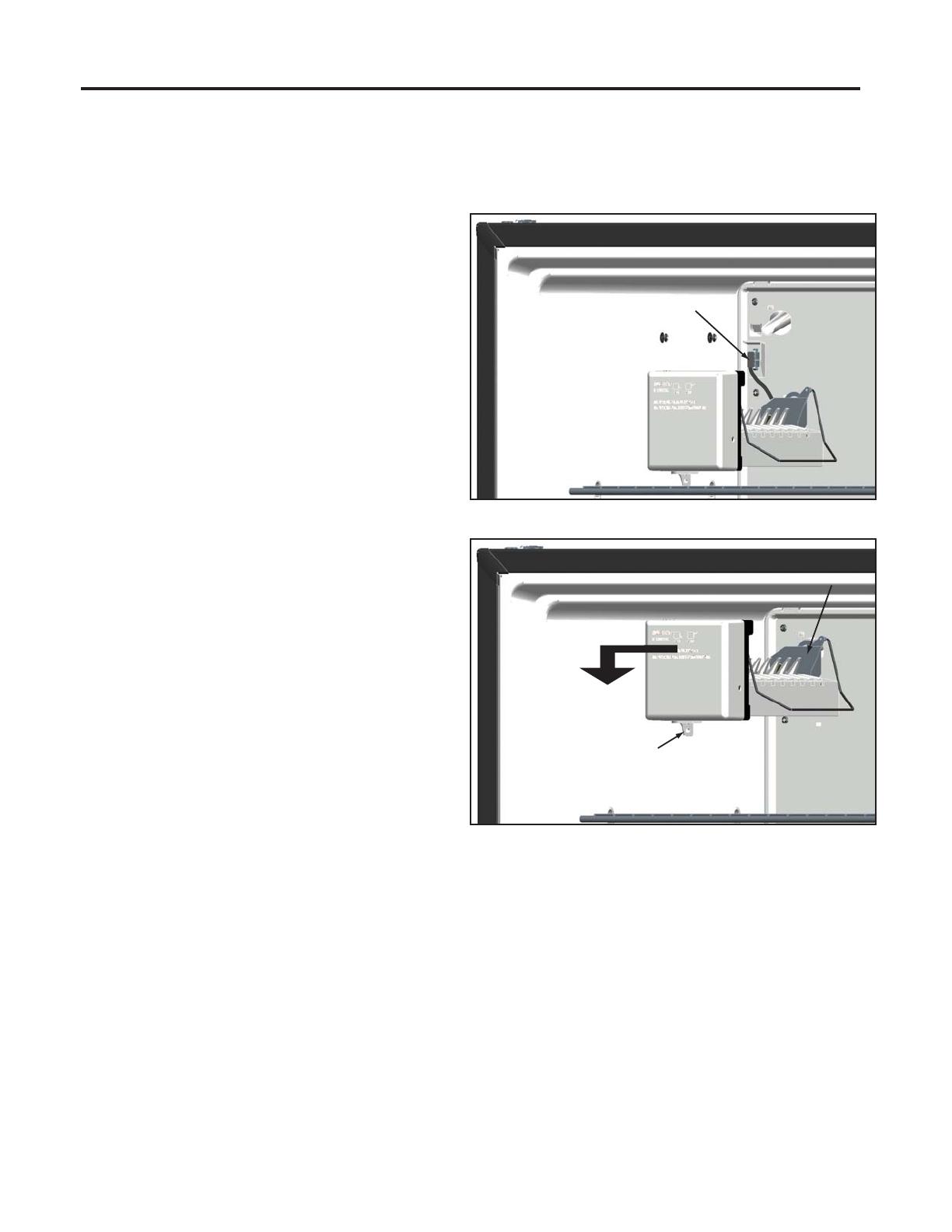
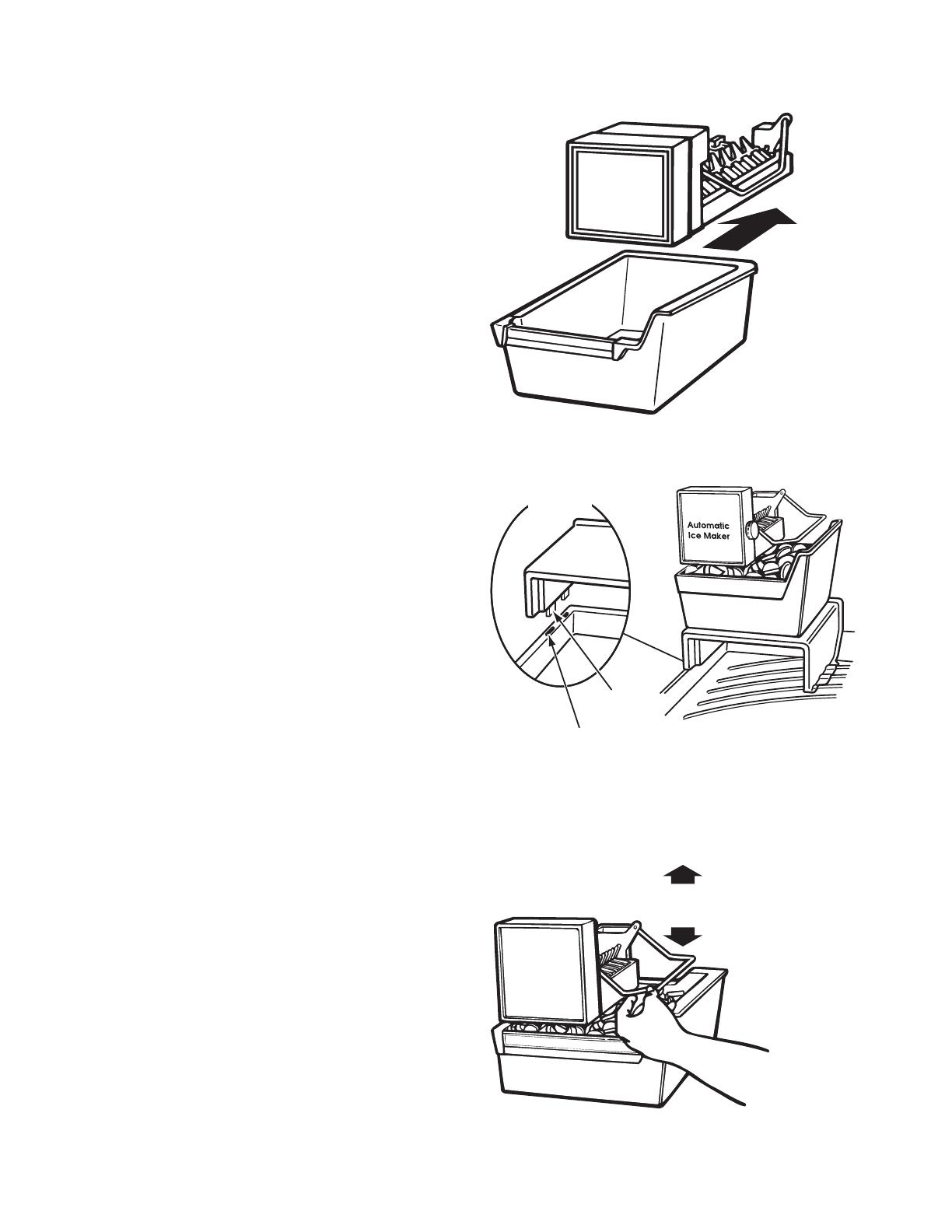
MODULE, MOTEUR ET ENSEMBLE DE SUPPORT
INSÉRER UN TOURNEVIS PHILLIPS DANS LES
OUVERTURES D'ACCÈS DU MODULE. DESSERRER LES
DEUX VIS. DÉCONNECTER LE BRAS DE COMMANDE.
DÉTACHER LE MOULE DE L'ENSEMBLE DE SUPPORT.
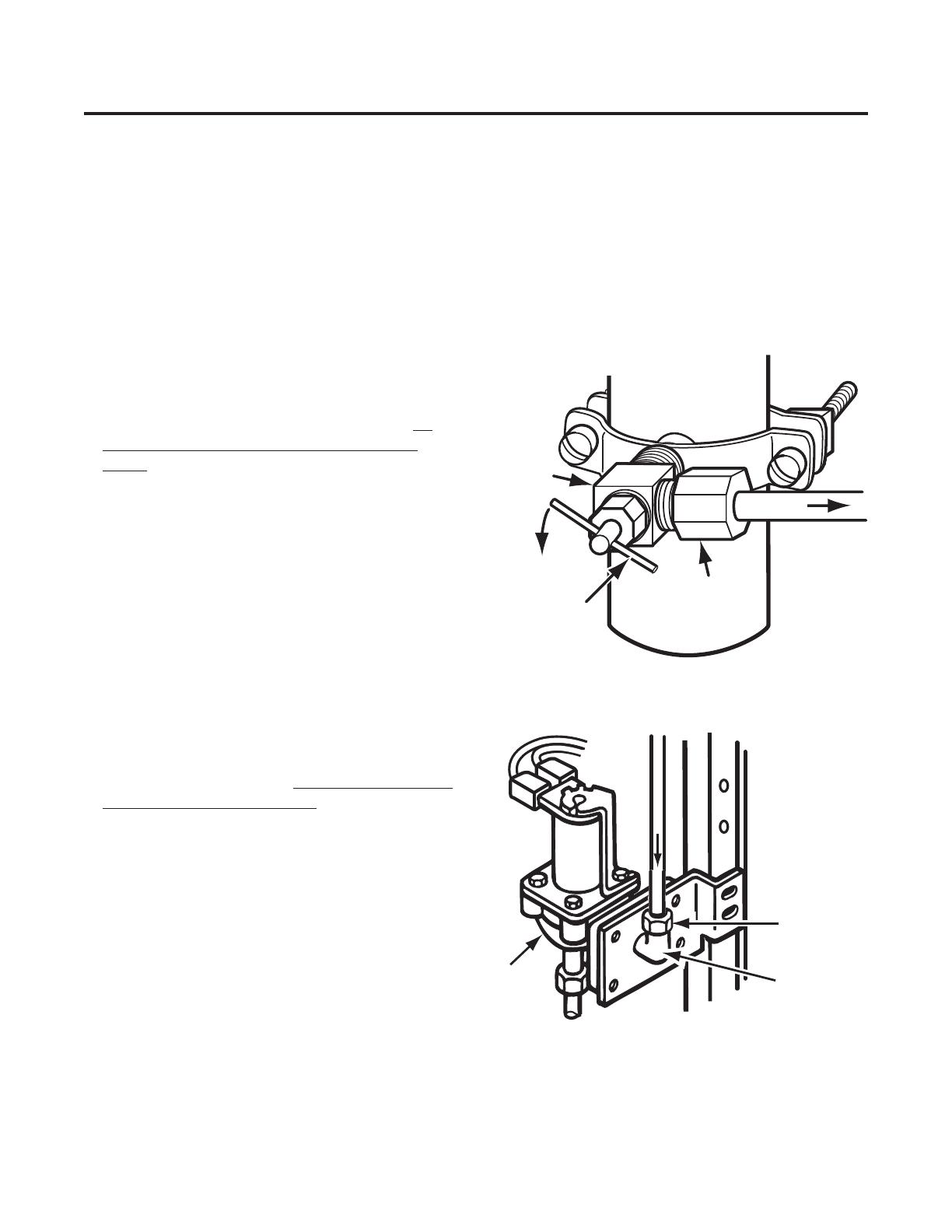
BRAS DE COMMANDE
DÉTACHER DE L'ENSEMBLE DE SUPPORT. RÉINSÉRER
À LA POSITION D'ABAISSEMENT COMPLET.
MOULE ET ÉLÉMENT CHAUFFANT
ÔTER MODULE, MOTEUR ET ENSEMBLE DE SUPPORT.
BILAME
ÔTER MODULE, MOTEUR ET ENSEMBLE DE SUPPORT.
ENLEVER LES AGRAFES DE RETENUE AVEC LE BILAME.
COUPELLE DE REMPLISSAGE
ÔTER MODULE, MOTEUR ET ENSEMBLE DE SUPPORT.
ÔTER LES LAMES D’ÉJECTION ET LE BRAS DE COMMANDE.
RETIRER LA COUPELLE DE REMPLISSAGE DU MOULE.
LAMES D’ÉJECTION OU DISPOSITIF D'ÉJECTION
ÔTER MODULE, MOTEUR, ENSEMBLE DE SUPPORT. LORS
DE LA RÉINSTALLATION DES LAMES D’ÉJECTION,
RÉALIGNER CORRECTEMENT L'ÉLÉMENT DE COUPLAGE
“D” AVEC LA CAME DE SÉLECTION DU MODÈLE.
CONTRÔLES DU MODULE AVEC UN OHMMÈTRE
(MACHINE À GLAÇONS PAS ALIMENTÉE ET LAMES
D’ÉJECTION À LA POSITION DE STATIONNEMENT)
POSITION
DU MODULE
POINTS
DE TEST
COMPOSANT OHMS
L-H ÉLÉMENT
CHAUFFANT
DU MOULE
FIXATION
SUR SUPPORT
72
L-M MOTEUR DÉCONNEXION
DU SUPPORT
8800
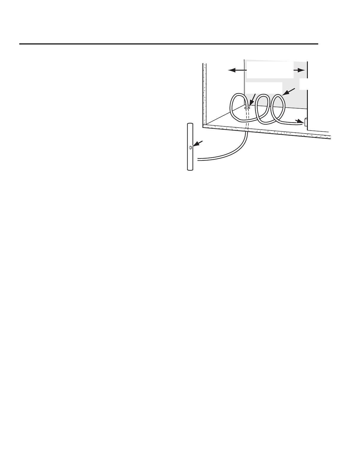
Réglage du niveau d'eau
LA ROTATION DE LA VIS DANS LE SENS ANTIHORAIRE
RÉDUIT LE REMPLISSAGE D'EAU.
• 1⁄2 TOUR REPRÉSENTE 20 CC ou 1,2 S
• UNE ROTATION COMPLÈTE REPRÉSENTE 40 CC ou 2,4 S
•
L'AMPLITUDE DE RÉGLAGE MAXIMALE CORRESPOND
À UNE ROTATION COMPLÈTE DANS UN SENS OU DANS
L'AUTRE; UNE ROTATION AU-DELÀ DE CETTE LIMITE
Vis de
fixation/dépose (3)
Bras de commande
Vis de réglage
Ouverture d'accès
pour les vis (Phillips)
de fixation du moule (2)
N
M
H
T
L
V
CONNECTEURS ENFICHABLES
(ÉJECTION ET REMPLISSAGE D'EAU)
POURRAIT FAIRE SUBIR DES DOMMAGES AU MODULE.