Patton SN-DTA User manual
- Category
- VoIP telephone adapters
- Type
- User manual
This manual is also suitable for

SN-DTA™
Single/Dual-Port ISDN BRI VoIP
Terminal Adapter
User Manual
Sales Office: +1 (301) 975-1000
Technical Support: +1 (301) 975-1007
E-mail: suppor[email protected]
www.patton.com
Part Number: 07MSNDTA-UM , Rev. A
Revised: September 27, 2011
Important
—
This is a Class B device and is intended for use in a light industrial or residential environment. It is not intended nor
approved for use in an industrial environment
.
This device is approved for connection to the public ISDN telecommunication network, over BRI/S0-ISDN interfaces.

Patton Electronics Company, Inc.
7622 Rickenbacker Drive
Gaithersburg, MD 20879 USA
Tel: +1 (301) 975-1000
Fax: +1 (301) 869-9293
Support: +1 (301) 975-1007
Web: www.patton.com
E-mail: support@patton.com
Trademark Statement
The term SN-DTA is a trademark of Patton Electronics Company. All other trade-
marks presented in this document are the property of their respective owners.
Copyright © 2011, Patton Electronics Company. All rights reserved.
The information in this document is subject to change without notice. Patton Elec-
tronics assumes no liability for errors that may appear in this document.
Important Information
To use virtual private network (VPN) and/or AES/DES/3DES encryption capabilities
with the SN-DTA, you may need to purchase additional licenses, hardware, software,
network connection, and/or service. Contact sales@patton.com or +1 (301) 975-1000
for assistance.
Warranty Information
The software described in this document is furnished under a license and may be used
or copied only in accordance with the terms of such license. For information about the
license, see Appendix F, "End user license agreement" on page 50 or go to
www.patton.com.
Patton Electronics warrants all SN-DTA components to be free from defects, and
will—at our option—repair or replace the product should it fail within one year from
the first date of the shipment.
This warranty is limited to defects in workmanship or materials, and does not cover
customer damage, abuse or unauthorized modification. If the product fails to perform
as warranted, your sole recourse shall be repair or replacement as described above.
Under no condition shall Patton Electronics be liable for any damages incurred by the
use of this product. These damages include, but are not limited to, the following: lost
profits, lost savings and incidental or consequential damages arising from the use of or
inability to use this product. Patton Electronics specifically disclaims all other warran-
ties, expressed or implied, and the installation or use of this product shall be deemed
an acceptance of these terms by the user.

3
Summary Table of Contents
1 General information...................................................................................................................................... 14
2 SN-DTA Applications overview..................................................................................................................... 19
3 SN-DTA installation ..................................................................................................................................... 21
4 SN-DTA initial configuration ....................................................................................................................... 26
5 Contacting Patton for assistance ................................................................................................................... 33
A Compliance information .............................................................................................................................. 36
B Specifications ................................................................................................................................................ 39
C Cabling ......................................................................................................................................................... 43
D Port pin-outs ................................................................................................................................................ 46
E SN-DTA factory configuration ..................................................................................................................... 48
F End user license agreement ........................................................................................................................... 50

4
Table of Contents
Summary Table of Contents ........................................................................................................................... 3
Table of Contents ........................................................................................................................................... 4
List of Figures ................................................................................................................................................. 7
List of Tables .................................................................................................................................................. 8
About this guide ............................................................................................................................................. 9
Audience................................................................................................................................................................. 9
Structure................................................................................................................................................................. 9
Precautions ........................................................................................................................................................... 10
Safety when working with electricity ...............................................................................................................11
General observations .......................................................................................................................................12
Typographical conventions used in this document................................................................................................ 13
General conventions .......................................................................................................................................13
1 General information...................................................................................................................................... 14
SN-DTA overview.................................................................................................................................................15
SN-DTA model codes .....................................................................................................................................16
SN-DTA/HP model codes ..............................................................................................................................16
SN-DTA rear panel ........................................................................................................................................17
SN-DTA front panel .......................................................................................................................................18
2 SN-DTA Applications overview..................................................................................................................... 19
Introduction..........................................................................................................................................................20
Typical application ................................................................................................................................................20
3 SN-DTA installation ..................................................................................................................................... 21
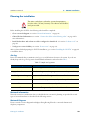
Planning the installation........................................................................................................................................22
Site log ............................................................................................................................................................22
Network information ......................................................................................................................................22
Network Diagram ...........................................................................................................................................22
IP related information .....................................................................................................................................23
Software tools .................................................................................................................................................23
Power source ...................................................................................................................................................23
Location and mounting requirements .............................................................................................................23
Installing the SN-DTA..........................................................................................................................................24
Placing the SN-DTA ......................................................................................................................................24
Installing cables ...............................................................................................................................................24
Connecting the SN-DTA to the ISDN terminals ......................................................................................24
Connecting the SN-DTA to the IP network .............................................................................................24
Connecting the SN-DTA to the power supply ..........................................................................................25
External S-Bus power supply .....................................................................................................................25
4 SN-DTA initial configuration ....................................................................................................................... 26
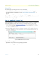
Introduction..........................................................................................................................................................27

5
SN-DTA User Manual
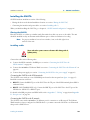
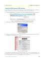
Start the SmartNode Discovery Tool.....................................................................................................................27
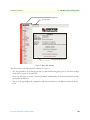
Access the Web Browser (GUI) Interface...............................................................................................................28
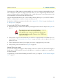
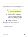
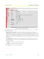
Configuring your SN-DTA ...................................................................................................................................30
Accessing the Internet .....................................................................................................................................30
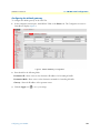
Configuring the default gateway .....................................................................................................................32
5 Contacting Patton for assistance ................................................................................................................... 33
Introduction..........................................................................................................................................................34
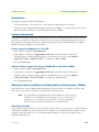
Contact information..............................................................................................................................................34
Patton support headquarters in the USA .........................................................................................................34
Alternate Patton support for Europe, Middle East, and Africa (EMEA) ..........................................................34
Warranty Service and Returned Merchandise Authorizations (RMAs)...................................................................34
Warranty coverage ..........................................................................................................................................34
Out-of-warranty service .............................................................................................................................35
Returns for credit ......................................................................................................................................35
Return for credit policy .............................................................................................................................35
RMA numbers ................................................................................................................................................35
Shipping instructions ................................................................................................................................35
A Compliance information .............................................................................................................................. 36
Compliance ...........................................................................................................................................................37
EMC Compliance ...........................................................................................................................................37
Safety Compliance ..........................................................................................................................................37
PSTN Compliance ..........................................................................................................................................37
CE Declaration of Conformity ..............................................................................................................................37
EG-Konformitätserklärung....................................................................................................................................38
Authorized European Representative .....................................................................................................................38
B Specifications ................................................................................................................................................ 39
DSP.......................................................................................................................................................................40
Voice connectivity .................................................................................................................................................40
Data connectivity ..................................................................................................................................................40
Voice processing (signaling dependent) .................................................................................................................40
Fax and modem support........................................................................................................................................40
Voice signalling .....................................................................................................................................................41
Voice routing—session router................................................................................................................................41
IP services..............................................................................................................................................................41
Management .........................................................................................................................................................42
Operating environment ...............................................................................................................................
..........42
Operating temperature ....................................................................................................................................42
Operating humidity ........................................................................................................................................42
System...................................................................................................................................................................42
Dimensions ...........................................................................................................................................................42
Weight and power dissipation ...............................................................................................................................42
C Cabling ......................................................................................................................................................... 43

6
SN-DTA User Manual
Introduction..........................................................................................................................................................44
Ethernet ................................................................................................................................................................44
ISDN BRI.............................................................................................................................................................45
D Port pin-outs ................................................................................................................................................ 46
Ethernet ................................................................................................................................................................47
ISDN BRI NT (Net) port .....................................................................................................................................47
ISDN BRI TE (User) port.....................................................................................................................................47
E SN-DTA factory configuration ..................................................................................................................... 48
Introduction..........................................................................................................................................................49
F End user license agreement ........................................................................................................................... 50
End User License Agreement.................................................................................................................................51
1. Definitions ..................................................................................................................................................51
2. Title ............................................................................................................................................................51
3. Term ...........................................................................................................................................................51
4. Grant of License ..........................................................................................................................................51
5. Warranty ....................................................................................................................................................51
6. Termination ................................................................................................................................................52
7. Other licenses .............................................................................................................................................52

7
List of Figures
1 SN-DTA . . . . . . . . . . . . . . . . . . . . . . . . . . . . . . . . . . . . . . . . . . . . . . . . . . . . . . . . . . . . . . . . . . . . . . . . . . . . . 15
2 SN-DTA rear panel . . . . . . . . . . . . . . . . . . . . . . . . . . . . . . . . . . . . . . . . . . . . . . . . . . . . . . . . . . . . . . . . . . . . . 17
3 SN-DTA front panel . . . . . . . . . . . . . . . . . . . . . . . . . . . . . . . . . . . . . . . . . . . . . . . . . . . . . . . . . . . . . . . . . . . . 18
4 SN-DTA application . . . . . . . . . . . . . . . . . . . . . . . . . . . . . . . . . . . . . . . . . . . . . . . . . . . . . . . . . . . . . . . . . . . . 20
5 SmartNode Discovery Tool window . . . . . . . . . . . . . . . . . . . . . . . . . . . . . . . . . . . . . . . . . . . . . . . . . . . . . . . . . 27
6 SN-DTA home page . . . . . . . . . . . . . . . . . . . . . . . . . . . . . . . . . . . . . . . . . . . . . . . . . . . . . . . . . . . . . . . . . . . . . 28
7 Main GUI elements . . . . . . . . . . . . . . . . . . . . . . . . . . . . . . . . . . . . . . . . . . . . . . . . . . . . . . . . . . . . . . . . . . . . . 29
8 Ethernet Configuration page . . . . . . . . . . . . . . . . . . . . . . . . . . . . . . . . . . . . . . . . . . . . . . . . . . . . . . . . . . . . . . . 31
9 Default Gateway Configuration . . . . . . . . . . . . . . . . . . . . . . . . . . . . . . . . . . . . . . . . . . . . . . . . . . . . . . . . . . . . 32
10 Typical Ethernet straight-through cable diagram . . . . . . . . . . . . . . . . . . . . . . . . . . . . . . . . . . . . . . . . . . . . . . . 44
11 Connecting an ISDN device . . . . . . . . . . . . . . . . . . . . . . . . . . . . . . . . . . . . . . . . . . . . . . . . . . . . . . . . . . . . . . . 45

8
List of Tables
1 General conventions . . . . . . . . . . . . . . . . . . . . . . . . . . . . . . . . . . . . . . . . . . . . . . . . . . . . . . . . . . . . . . . . . . . . . 13
2 SmartNode SN-DTA BRI Ports and Voice Channels . . . . . . . . . . . . . . . . . . . . . . . . . . . . . . . . . . . . . . . . . . . . 16
3 Rear panel ports . . . . . . . . . . . . . . . . . . . . . . . . . . . . . . . . . . . . . . . . . . . . . . . . . . . . . . . . . . . . . . . . . . . . . . . . 17
4 SN-DTA LED definitions . . . . . . . . . . . . . . . . . . . . . . . . . . . . . . . . . . . . . . . . . . . . . . . . . . . . . . . . . . . . . . . . 18
5 Sample site log entries . . . . . . . . . . . . . . . . . . . . . . . . . . . . . . . . . . . . . . . . . . . . . . . . . . . . . . . . . . . . . . . . . . . . 22
6 SmartNode weight and maximum power specifications . . . . . . . . . . . . . . . . . . . . . . . . . . . . . . . . . . . . . . . . . . 42
7 RJ-45 socket . . . . . . . . . . . . . . . . . . . . . . . . . . . . . . . . . . . . . . . . . . . . . . . . . . . . . . . . . . . . . . . . . . . . . . . . . . . 47
8 RJ-45 socket . . . . . . . . . . . . . . . . . . . . . . . . . . . . . . . . . . . . . . . . . . . . . . . . . . . . . . . . . . . . . . . . . . . . . . . . . . . 47
9 RJ-45 socket . . . . . . . . . . . . . . . . . . . . . . . . . . . . . . . . . . . . . . . . . . . . . . . . . . . . . . . . . . . . . . . . . . . . . . . . . . . 47

9
About this guide
This guide describes the SN-DTA hardware, installation and basic configuration. For detailed software config-
uration information refer to the SmartWare Software Configuration Guide and the available Configuration
Notes.
Audience
This guide is intended for the following users:
• Operators
• Installers
• Maintenance technicians
Structure
This guide contains the following chapters and appendices:
• Chapter 1 on page 14 provides information about the SN-DTA’s features and capabilities
• Chapter 2 on page 19 contains an overview describing the SN-DTA’s operation and applications
• Chapter 3 on page 21 provides hardware installation procedures
• Chapter 4 on page 26 provides quick-start procedures for configuring the SN-DTA
• Chapter 5 on page 33 contains information on contacting Patton technical support for assistance
• Appendix A on page 36 contains compliance information for the SN-DTA
• Appendix B on page 39 contains specifications for the SN-DTA
• Appendix C on page 43 provides cable recommendations
• Appendix D on page 46 describes the SN-DTA’s ports and pin-outs
• Appendix E on page 48 lists the factory configuration settings for the SN-DTA
• Appendix F on page 50 provides license information that describes acceptable usage of the software pro-
vided with the SN-DTA
For best results, read the contents of this guide before you install the SN-DTA.

10
SN-DTA User Manual About this guide
Precautions
Notes, cautions, and warnings, which have the following meanings, are used throughout this guide to help you
become aware of potential problems. Warnings are intended to prevent safety hazards that could result in per-
sonal injury. Cautions are intended to prevent situations that could result in property damage or
impaired functioning.
Note
A note presents additional information or interesting sidelights.
The alert symbol and IMPORTANT heading calls attention to
important information.
The alert symbol and CAUTION heading indicate a potential haz-
ard. Strictly follow the instructions to avoid property damage.
The shock hazard symbol and CAUTION heading indicate a
potential electric shock hazard. Strictly follow the instructions to
avoid property damage caused by electric shock.
The alert symbol and WARNING heading indicate a potential safety hazard.
Strictly follow the warning instructions to avoid personal injury.
The shock hazard symbol and WARNING heading indicate a potential electric
shock hazard. Strictly follow the warning instructions to avoid injury caused
by electric shock.

11
SN-DTA User Manual About this guide
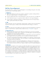
Safety when working with electricity
•
Do not open the device when the power cord is connected. For systems
without a power switch and without an external power adapter, line volt-
ages are present within the device when the power cord is connected.
•
For devices with an external power adapter, the power adapter shall be a
listed Limited Power Source The mains outlet that is utilized to power the
device shall be within 10 feet (3 meters) of the device, shall be easily
accessible, and protected by a circuit breaker in compliance with local regu-
latory requirements.
•
For AC powered devices, ensure that the power cable used meets all appli-
cable standards for the country in which it is to be installed.
•
For AC powered devices which have 3 conductor power plugs (L1, L2 &
GND or Hot, Neutral & Safety/Protective Ground), the wall outlet (or
socket) must have an earth ground.
•
For DC powered devices, ensure that the interconnecting cables are rated
for proper voltage, current, anticipated temperature, flammability, and
mechanical serviceability.
•
WAN, LAN & PSTN ports (connections) may have hazardous voltages
present regardless of whether the device is powered ON or OFF. PSTN
relates to interfaces such as telephone lines, FXS, FXO, DSL, xDSL, T1, E1,
ISDN, Voice, etc. These are known as “hazardous network voltages” and
to avoid electric shock use caution when working near these ports. When
disconnecting cables for these ports, detach the far end connection first.
•
Do not work on the device or connect or disconnect cables during periods of
lightning activity
This device contains no user serviceable parts. This device can only be
repaired by qualified service personnel.
In accordance with the requirements of council directive 2002/
96/EC on Waste of Electrical and Electronic Equipment (WEEE),
ensure that at end-of-life you separate this product from other
waste and scrap and deliver to the WEEE collection system in
your country for recycling.
WARNING
WARNING

12
SN-DTA User Manual About this guide
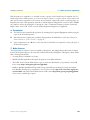
General observations
• Clean the case with a soft slightly moist anti-static cloth
• Place the unit on a flat surface and ensure free air circulation
• Avoid exposing the unit to direct sunlight and other heat sources
• Protect the unit from moisture, vapors, and corrosive liquids
Always follow ESD prevention procedures when removing and
replacing cards.
Wear an ESD-preventive wrist strap, ensuring that it makes good
skin contact. Connect the clip to an unpainted surface of the
chassis frame to safely channel unwanted ESD voltages
to ground.
To properly guard against ESD damage and shocks, the wrist
strap and cord must operate effectively. If no wrist strap is avail-
able, ground yourself by touching the metal part of the chassis.
CAUTION

13
SN-DTA User Manual About this guide
Typographical conventions used in this document
This section describes the typographical conventions and terms used in this guide.
General conventions
The procedures described in this manual use the following text conventions:
Table 1. General conventions
Convention Meaning
Garamond blue type
Indicates a cross-reference hyperlink that points to a figure, graphic, table, or sec-
tion heading. Clicking on the hyperlink jumps you to the reference. When you
have finished reviewing the reference, click on the Go to Previous View
button in the Adobe® Acrobat® Reader toolbar to return to your starting point.
Futura bold type Commands and keywords are in boldface font.
Futura bold-italic type Parts of commands, which are related to elements already named by the user, are
in boldface italic font.
Italicized Futura type Variables for which you supply values are in italic font
Futura type Indicates the names of fields or windows.
Garamond bold type Indicates the names of command buttons that execute an action.
< > Angle brackets indicate function and keyboard keys, such as <SHIFT>, <CTRL>,
<C>, and so on.
[ ] Elements in square brackets are optional.
{a | b | c} Alternative but required keywords are grouped in braces ({ }) and are separated
by vertical bars ( | )
blue screen Information you enter is in blue screen font.
screen Terminal sessions and information the system displays are in screen font.
node The leading IP address or nodename of a SN-DTA is substituted with node in
boldface italic font.
SN The leading SN on a command line represents the nodename of the SN-DTA
# An hash sign at the beginning of a line indicates a comment line.

14
Chapter 1 General information
Chapter contents
SN-DTA overview.................................................................................................................................................15
SN-DTA model codes .....................................................................................................................................16
SN-DTA/HP model codes ..............................................................................................................................16
SN-DTA rear panel ........................................................................................................................................17
SN-DTA front panel .......................................................................................................................................18

SN-DTA overview 15
SN-DTA User Manual 1 • General information
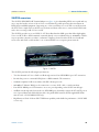
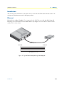
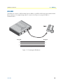
SN-DTA overview
The SN-DTA ISDN BRI VoIP Terminal Adapter (see figure 1) gives demanding ISDN users a quick and easy
way to reap the benefits of state-of-the art Voice-over-IP technology while preserving their investments in
ISDN phones and PBX equipment. Supporting two or four concurrent voice or fax calls over an IP network,
the SN-DTA is a simple and cost-effective way for home and home-office users to connect their ISDN termi-
nals to the cost-saving world of Voice-over-IP.
The SN-DTA provides one to two ISDN S
0
(S/T) Basic Rate Interface (BRI) ports that deliver high-quality
Voice-over-IP (VoIP) to ISDN terminals, connected directly or via a residential S-bus. A 10/100 Base-T Ether-
net port provides connection to either 1) an Internet Telephony Service Provider (ITSP) via a broadband
access router and xDSL or cable modem, or 2) a remote IP-PBX over a corporate-private network.
Figure 1. SN-DTA
The SN-DTA performs the following major functions:
• Two/four channels of Voice or FAX-over-IP through one/two Euro-ISDN BRI/S
0
port (NT orientation).
• Provides line power to connected ISDN phone or PBX terminals (TE orientation).
• Standards-compliant VoIP in accordance with SIP or H.323 protocols.
• 10/100Base-T Ethernet WAN port for connection to a router, xDSL, cable, or wireless modem.
• Euro-ISDN BRI/S0 port (NTorientation, one to two ports depending on the SN-DTA model type)
• A fallback cut-through relay between the two ISDN BRI ports electrically connects the NT and TE port in
case of power failure and enables life-line calls to the public ISDN network (PSTN-supplied ISDN line
must be used). (SN-DTA/2BIS2V/EUI only)
• High Precision Clock—Delivers DECT PBX interoperability with reliable fax performance. (SN-DTA/HP
versions only)

SN-DTA overview 16
SN-DTA User Manual 1 • General information
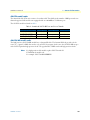
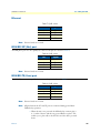
SN-DTA model codes
The SmartNode SN-DTA series consists of several models. They differ in the number of BRI ports and voice
channels supported. All models come equipped with one 10/100/Base-Tx Ethernet port.
The SN-DTA models are listed in table 2.
SN-DTA/HP model codes
The high precision SN-DTA/HP models have a Stratum III clock. The Stratum III clock provides a clock
source of < 5 ppm. For PBXs that used to rely on PSTN for accurate clock source, the SN-DTA/HP can pro-
vide a PSTN-equivalent high precision clock. The popular DECT PBX needs such high precision clocks.
Note
For high precision clock models, replace SN-DTA with SN-
DTA/HP in the model code.
For example: SN-DTA/2BIS4VHPEUI
Table 2. SmartNode SN-DTA BRI Ports and Voice Channels
Model BRI NT port BRI TE port Voice Channels
SN-DTA/1BIS2V/EUI 1 - 2
SN-DTA/2BIS4V/EUI 2 - 4
SN-DTA/2BIS2V/EUI 1 1 2

SN-DTA overview 17
SN-DTA User Manual 1 • General information
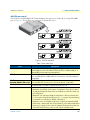
SN-DTA rear panel
The SN-DTA is an ISDN BRI VoIP Terminal Adapter that supports two VoIP calls via a single ISDN BRI
port (see figure 2). The SN-DTA rear panel ports are described in table 3.
Figure 2. SN-DTA rear panel
Table 3. Rear panel ports
Port Description
ETH (LAN)
Switched Auto-MDX Fast-Ethernet port, RJ-45 (see
figure 2
), connect the unit to an
Internet Telephony Service Provider (ITSP) [via an xDSL or cable modem] or a
remote IP-PBX [via a private corporate network].
BRI NT
ISDN BRI NT (Net) port, RJ-45 S0 (S/T)-interface (see
figure 2
), connects the
unit to an ISDN phone or PBX trunk-port. Point-to-point or point-to-multipoint
configurable.
BRI TE
(SN-DTA/2BIS2V/EUI only)
ISDN BRI TE (Usr) port, RJ-45 S0 (S/T)-interface (see
figure 2
), connects the
unit to an ISDN NT. Point-to-point or point-to-multipoint confgurable.
12V DC, 1.0A
The SN-DTA has a 12V DC 1A power input (see
figure 2
).
Reset
The reset button (see
figure 2
) has three functions:
•
Restart the unit with the current startup configuration—Press (for less than 1
second) and release the Reset button to restart the unit with the current star-
tup configuration.
•
Restart the unit with factory default configuration—Press the Reset button
for 5 seconds until the Power LED (see
figure 3
on page 18) starts blinking
to restart the unit with factory default configuration.
•
Restart the unit in bootloader mode (to be used only by trained SN-DTA
technicians)—Starting with the unit powered off, press and hold the Reset
button as you apply power to the unit. Release the Reset button when the
Power LED starts blinking so the unit will enter bootloader mode.
ETH 0/0
Reset
12V D
C 1A
LAN NT NT
BRI 0/0
BRI 0/1

SN-DTA overview 18
SN-DTA User Manual 1 • General information
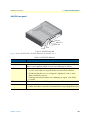
SN-DTA front panel
Figure 3. SN-DTA front panel
Figure 3 shows SN-DTA LEDs, the LED definitions are listed in table 4.
Table 4. SN-DTA LED definitions
LED Description
Note If an error occurs, all LEDs will flash once per second.
Power When lit, indicates power is applied and the unit is in normal operation. Off indi-
cates no power applied. Flashes once per second during boot (startup).
VoIP
•
On indicates that the SN-DTA is registered to an H.323 gatekeeper/SIP server,
or, in the case of direct routing, has at least one active VoIP connection.
•
Off indicates that the unit is not configured or registered, or has no active
direct-routed VoIP connection.
•
Flashing green indicates that the unit is attempting to register or has failed
to register.
BRI Off indicates no active calls. Blinking when one or two B-channels are connected.
Ethernet
•
On when the Ethernet connection has a link indication.
•
Flashes when data is received or transmitted at the corresponding Ethernet port.
VoIP
BRI/So 0/1
Power
Ethernet
BRI/So 0/0

19
Chapter 2 SN-DTA Applications overview
Chapter contents
Introduction..........................................................................................................................................................20
Typical application ................................................................................................................................................20

Introduction 20
SN-DTA User Manual 2 • SN-DTA Applications overview
Introduction
Patton’s SN-DTA BRI VoIP Terminal Adapter provides ISDN users a quick and easy migration path to the
cost-saving world of IP telephony. This chapter describes typical applications for which the SN-DTA is
uniquely suited.
Whether you are connecting to an Internet Telephony Service Provider (ITSP) or the phone system at your
main office, SN-DTA provides the features you need for high-quality, state-of-the-art Voice-over-IP. In either
scenario, Patton’s robust and mature software provides call-property adaptation with regular-expression map-
ping between ISDN and SIP/H.323 signaling schemes. In the corporate private network, intelligent and con-
figurable call-routing supports existing numbering plans for ultimate useability.
Note
Detailed configuration information for the applications can be found online
from the Patton webserver at www.patton.com.
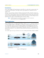
Typical application
The SmartNode SN-DTA with one or two ISDN BRI ports can be used to make and receive calls to and from
Internet Telephony services on any ISDN Terminal (Phone or PBX) (see Figure 4). The SN-DTA enables the
connection of ISDN terminals or SOHO PBXs to a VoIP network or Internet Telephony Service. It can con-
nect to ISDN PBXs in point-to-point mode and ISDN Terminals in point-multipoint mode (S-Bus) and
offers a feature rich configuration interface. An optional BRI TE port (SN-DTA/2BIS2V/EUI only) can be
used for fallback to the local PSTN. Using individually configurable routing tables, an outbound call can be
directed to the local PSTN or to the VoIP network. Inbound calls from the Internet and the PSTN can ring
the same phone.
The SN-DTA supports three types of Internet-access service, including fixed-IP address, DHCP, and PPPoE.
Figure 4. SN-DTA application
Page is loading ...
Page is loading ...
Page is loading ...
Page is loading ...
Page is loading ...
Page is loading ...
Page is loading ...
Page is loading ...
Page is loading ...
Page is loading ...
Page is loading ...
Page is loading ...
Page is loading ...
Page is loading ...
Page is loading ...
Page is loading ...
Page is loading ...
Page is loading ...
Page is loading ...
Page is loading ...
Page is loading ...
Page is loading ...
Page is loading ...
Page is loading ...
Page is loading ...
Page is loading ...
Page is loading ...
Page is loading ...
Page is loading ...
Page is loading ...
Page is loading ...
Page is loading ...
-
 1
1
-
 2
2
-
 3
3
-
 4
4
-
 5
5
-
 6
6
-
 7
7
-
 8
8
-
 9
9
-
 10
10
-
 11
11
-
 12
12
-
 13
13
-
 14
14
-
 15
15
-
 16
16
-
 17
17
-
 18
18
-
 19
19
-
 20
20
-
 21
21
-
 22
22
-
 23
23
-
 24
24
-
 25
25
-
 26
26
-
 27
27
-
 28
28
-
 29
29
-
 30
30
-
 31
31
-
 32
32
-
 33
33
-
 34
34
-
 35
35
-
 36
36
-
 37
37
-
 38
38
-
 39
39
-
 40
40
-
 41
41
-
 42
42
-
 43
43
-
 44
44
-
 45
45
-
 46
46
-
 47
47
-
 48
48
-
 49
49
-
 50
50
-
 51
51
-
 52
52


Patton SN-DTA User manual
- Category
- VoIP telephone adapters
- Type
- User manual
- This manual is also suitable for
Ask a question and I''ll find the answer in the document
Finding information in a document is now easier with AI
Related papers
-
Patton SmartNode 4970A Series User manual
-
-
-
-
-
-
-
-
-
Other documents
-
Patton electronics SMART-DTA 07MSDTA-QS User manual
-
Patton electronic 1200 User manual
-
-
-
-
-
-
Philips Electronics Singapore Pte RCSRC2843001 User manual
-
ZyXEL P-2602HWNLI User manual
-