Page is loading ...

JetNet 3008 v3
JetNet 3008f v3
Industrial 8-port Ethernet Switch
User’s Manual
Version:1.1 Date: 26-Jun-2013

Content
1. Introduction ................................................................. 1
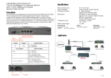
1-1. Features ...................................................................... 2
1-2. Packing List ................................................................. 2
2. Hardware Description .................................................. 3
2.1. Dimensions ........................................................... 3
2-2 Front Panel ........................................................... 4
2-3. Bottom View .......................................................... 4
2-4. LED Indicators ...................................................... 5
2-5. Ports ..................................................................... 6
3. Mounting Installation ................................................... 7
DIN-Rail Mounting ............................................................... 7
4. Hardware Installation .................................................. 9
4-1. Wiring the DC Power Inputs ................................ 10
4-2. Wiring the Alarm Relay ....................................... 11
4-3. Wiring Earth Grounding ....................................... 12
4-4. Enabled the Event Alarm Function ...................... 12
4-5. Cabling ................................................................ 14
4-6. System Power-On and Testing ........................... 15
5. Packet forwarding and filtering ability ........................ 19
5-1. Broadcast Control ............................................... 19
5-2. Quality of Service ................................................ 19
6. Trouble shooting ....................................................... 22

Federal Communications Commission (FCC) Statement
This equipment has been tested and found to comply with the limits for a Class A digital
device, pursuant to Part 15 of the FCC Rules. These limits are designed to provide
reasonable protection against harmful interference when the equipment is operated in a
commercial environment. This equipment generates, uses, and can radiate radio
frequency energy and, if not installed and used in accordance with the instruction
manual, may cause harmful interference to radio communications. Operation of this
equipment in a residential area is likely to cause harmful interference in which case the
user will be required to correct the interference at his expense.
The user is cautioned that changes and modifications made to the equipment without
approval of the manufacturer could void the user's authority to operate this equipment.

JetNet 3008 v3 / JetNet 3008f v3 User’s Manual
1
1. Introduction
The JetNet 3008V3/ 3008f V3 is an 8-port Fast Ethernet switch designed
with enhanced design specifications, including wider operating
temperature and power input range to best fit in heavy industrial field
applications. It is equipped with 2.0Gbps High performance switching
engine with packet forwarding and filtering mechanism to fulfill higher
performance industrial data communication requirements in field site
deployments. The graceful packet forwarding ability enables the JetNet
3008f V3 to handle from 64 to 1522 bytes packet sizes into 2 forwarding
priority queues which is compliant with IEEE 802.1p Class of Service for
providing best data forwarding performance.
In addition, to ensure best network performance, both broadcast storm
filtering and flow control functions can ensure your data traffic delivery to
destination without traffic congestion. The combination of enhanced
network features and rugged specs make the JetNet 3008 V3 /JetNet
3008f V3 become your best entry-level networking solution in industrial
deployments.
Reliable Power System Design
In order to operate under harsh environment of industrial sites, JetNet
3008 V3 series are designed with redundant wide power input 10~60VDC
range as well as auto polarity reverse function to ensure the switch’s
capability of transmitting data under poor DC power sourcing.
Brilliant Electromagnetic Interference Immunity
In industrial applications with widespread electromagnetic interference,
such as the automation control and high power motor operating
environments, the switch’s electromagnetic immunity ability will affect the
quality of data transfer. The JetNet 3008 V3, compliant with the
electromagnetic interference requirements for Heavy Industrial
applications, provides a high level of electromagnetic susceptibility
exceeding the IEC/EN 61000-6-2 standard with distinguished electrical
slow transient (Surge), radio-frequency electromagnetic field (RS),
Electrical Fast Transient (EFT) protections. Equipped with a rugged
aluminum case with IP31 grade protection and high thermal conductivity
design, it is capable of resisting -25~70℃ (JetNet 3008), -10~70℃
(JetNet 3008f) and -40~75℃(JetNet 3008-w/ JetNet 3008f-w) wide
temperature ranges while providing reliable connectivity under harsh
industrial environments.

2
This session will introduce following information of JetNet 3008 for your
reference.
1. Features
2. Packing list
1-1. Features
8 10/100TX ports – JetNet 3008
6 10/100TX, plus 2 100FX in Multi-mode or Single-mode – JetNet
3008f
Compact size with full power redundancy
2.0Gbps Switch Fabric with excellent data exchange performance
QoS for packet forwarding precedence
Broadcast storm packet filtering
Port and power event alarm
Aluminum metal case with IP31 grade protection
DIN rail installation
Dual power input DC10~60V
Support 1.5KV Hi-Pot isolation protection
Operating temperature: -25~70
o
C (JetNet 3008 V3) and -40~75
o
C
(JetNet 3008-w V3), -10~70
o
C (JetNet 3008f V3) and -40~75
o
C
(JetNet 3008f-w V3)
1-2. Packing List
JetNet 3008 v3/JetNet 3008f v3 Industrial 8-port Fast Ethernet Switch is
packaged with the following items:
JetNet 3008 or JetNet 3008f
Quick Installation Guide
Contact your sales representative if any item is missing or damaged.
JetNet3008 v3 JetNet 3008f v3
Quick Installation Guide

3
2. Hardware Description
This session will introduce the hardware information as following:
2-1. dimensions
2-2. Front Panel
2-3. Bottom View
2-4. LEDs of system and port
2-5. Connectors
2.1. Dimensions
JetNet 3008 / JetNet 3008f 8-port Industrial Fast Ethernet Rail Switch
dimensions are 120 mm (H) x 55 mm (W) x 108 mm (D), detail
mechanical design drawings are attached as following:

4
2-2 Front Panel
The Front Panel of the JetNet 3008/JetNet 3008f Industrial 8-port Fast
Ethernet Switch is shown in Figure A.
Figure A. Front Panel of the JetNet 3008 / JetNet 3008f.
2-3. Bottom View
The bottom view of the JetNet 3008/JetNet 3008f Industrial 8-port
Ethernet Switch consists of one 6-pin removable terminal block connector
for two DC power inputs and event alarm output. There is one 9-pin DIP
SWITCH on the bottom for alarm control of port or power event selection.

5
Figure B. Bottom view of the JetNet 3008/ JetNet 3008f
2-4. LED Indicators
There are some system diagnostic LEDs and Ethernet Port LEDs located
on the front panel of JetNet3008 / JetNet 3008f Industrial 8-port Ethernet
Switch. These LED indicators provide administrators with real-time system
status. The table-1 gives the descriptions of the function of each LED
indicator.
LED
Status
Description
PWR1
Green on
Power is on.
Off
No power is being supplied.
PWR2
Green on
Power is on.
Off
No power is being supplied.
Alm
Red on
Port link down or power failure event
occurred.
Off
No event.
Port 1~8 (JetNet 3008)
Port 1~6 (JetNet 3008f)
Link
(Green on )
A network device is detected and link
up.
Activity (Green blinks)
The port is transmitting or receiving
packets from the TX device.
Speed
(Yellow on/ 100Mbps)
A network device is detected and link on
100Mbps.
Speed
(Yellow off)
A network device is detected and link on
10Mbps.

6
Fiber port #7, #8
(JetNet 3008f)
100Mbps Link (Green
on)
The port is operating in full-duplex
mode.
100Mbps Activity
(Green Blinks)
The port is transmitting or receiving
packets from the TX device.
Table 1
2-5. Ports
RJ-45 ports (Auto MDI/MDIX): JetNet 3008 has eight 10/100 Mbps
auto-sensing RJ-45 ports for 10Base-T or 100Base-TX device connection
and JetNet 3008f has six 10/100Mbps RJ-45 ports and two 100Mbps fiber
ports for multi-mode or single-mode fiber cable in SC type connector. The
RJ-45 ports will auto-detect 10Base-T and 100Base-TX connections. Auto
MDI/MDIX function allows users to connect another switch or workstation
without changing straight through or crossover cabling. See Figure C and
C-1 for the schematic diagram of straight through and crossover cabling.
Figure C Straight Through Cabling Schematic Figure C-1 Cross Over Cabling
Schematic
All RJ-45 ports of JetNet 3008/ JetNet 3008f support auto-MDI/MDI-X
function. When you use an Ethernet cable to connect other devices, such
as computers, switches or hubs, pin 1, 2, 3, and 6 of the 8-pin RJ45
connector are used to communicate with the connected devices. Pin1, 2,
3, and 6’s signals are converted by the MDI-X function, as shown in Table
-2.
Pin MDI-X
Signals
MDI Signals

7
1
RD+
TD+
2
RD-
TD-
3
TD+
RD+
6
TD-
RD-
Table-2
3. Mounting Installation
DIN-Rail Mounting
The DIN-Rail clip is already attached on the rear side of JetNet 3008/
JetNet 3008f. JetNet 3008 series supports EN 50022 standard DIN Rail, in
the following diagram includes the dimension of EN 55022 DIN Rail for
your reference.
The DIN rail should behind the
spring when install the JetNet
3008/JetNet 3008f onto the
standard DIN Rail.
Follow the steps below to mount
the JetNet 3008 /JetNet 3008f
on the DIN-Rail track.
1. Insert the upper end of the
DIN-Rail clip into the back of
the DIN-Rail track from its
upper side
2. Lightly push the bottom of the
DIN-Rail clip into the track.
3. Check if the DIN-Rail clip is

8
tightly attached to the track.
4. To remove the JetNet 3008/ JetNet 3008f-m from the track, reverse the
steps above.

9
4. Hardware Installation
The following figure illustrates a typical application of JetNet 3008 / JetNet
3008f in field site. It includes Enterprise communication backbone network,
Factory communication, field site communication and field site control
layers. The control equipments access and report production information
through the JetNet 3008 or JetNet 3008f and uplink to factory
communication level by fiber or copper which with network redundancy.
This session will introduce the hardware installation, includes:
4-1. Wiring the DC Power Inputs
4-2. Wiring the Relay Alarm
4-3. Wiring Earth Grounding
4-4 Enable Alarm Relay Function
4-5. Cabling
4-6. System Power-On and Testing

10
4-1. Wiring the DC Power Inputs
Follow the steps below to wire JetNet 3008’s / JetNet 3008f’s dual DC
power inputs.
[Note] The suitable electric wire ranges is from 12 to 24 AWG.
Equipment intended for installation in a Restricted Access Location.
Before install power, be sure the power supply module is compliance with
UL certificated LPS power and the power system is shut down to avoid
any damage. About the wiring please refer following diagram.
V- V+
V- V+
1. Insert the positive and negative wires into the V+ and V-
contacts respectively of the terminal block connector
2. Tighten the wire-clamp screws to prevent the DC wires
from being loosened.

11
4-2. Wiring the Alarm Relay
JetNet 3008 /JetNet 3008f provides one dry relay output for power or port
link event; the alarm relay is “Normal open” and form a close circuit when
The relay conductor ability is 12W when it connects with a DC 24V power
source and maximum current is 0.5A. In the following diagram shows how
to make an alarm circuit.
Maximum 0.5A current / DC24V

12
4-3. Wiring Earth Grounding
In the real fields, there might have a lot of automatic device, such as AC
motors, electric welding machine, power generator; those devices will
generate electromagnetic and disturb communications. To prevent those
noises, the switch should be well earthed. In the figure-shows how to
make connection.
4-4. Enabled the Event Alarm Function
This session introduces how to configure and enable the event alarm to
alert maintenance engineer once system event occurred. Both of JetNet
3008 and JetNet 3008f equipped with one dry relay output for port link fails
or power fails. The feature is controlled by digital control circuits and effect
immediately without system reset when DIP SWITCH changed.
On the bottom side of JetNet 3008 and JetNet 3008f, there is one 9-Pin
DIP SWITCH for alarm control. By inserting the port and power wiring,
setting the DIP SWITCH of the intended Alarm to “ON”, the relay output
will form a short circuit if alarm occurred.

13
The DIP SWITCH Setting for the Alarm Relay Output is show as following
table.
Pin No. #
Status
Description
P1 to P8
(Pin1 ~8)
ON
To enable port link down alarm at this port.
Off
To disable port link down alarm at this port.
P9
ON
To enable power failure alarm.
Off
To disable power failure alarm.

14
4-5. Cabling
The UTP cable connection between the JetNet 3008 and the attached
devices (switches, hubs, workstations, etc.) must be less than 100 meters
(328 ft.) long.
The transmission distance of JetNet 3008f is depends on the type of fiber
transceiver model and the attenuation of optical fiber cable. The following
information is fiber transceiver specification of JetNet 3008f series. Please
ensure the cable attenuation between two far end nodes is less than the
power budget of fiber transceiver. Table-3 shows the specification of
optical fiber transceiver JetNet 3008f used.
model
Cable Type
Con.
Wavelength
TXPwr(min)
TxPwr(Max)
RxPwr(Min)
RxPwr(Max)
LinkBudg(dbm)
Distance(km)
JetNet
3008f-m
Multi-mode
50~62.5/125
SC
1310nm
-20dBm
-14dBm
-31dBm
0dBm
11dBm
2Km/5Km
Note1
JetNet
3008f-s
Single-mode
8~10/125
SC
1310nm
-15dBm
-8dBm
-34dBm
-8dBm
19dBm
30km
Table -3 Specification of Fiber Transceiver
TxPwr (Min): Minimum Transmit power TxPwr (Max): Maximum Transmit power
RxPwr (Min): Maximum Receive sensitivity RxPwr (Max): Minimum Receive sensitivity
Link Budget= TxPwr (Min) –Rx Pwr (Min)
Note:
1. In the IEEE standard, it suggests the available transmission distance is 2KM for 62.5/125um
fiber optical cable in 1310nm wave length. Actually, the attenuation of multi-mode 62.5/125um
optical fiber cable is 1.5dBm/KM and the maximum link distance can up to 4~5km.
2. IEEE organization recommends maximum optical fiber cable distances as defined in
the table-4 shows as below:
Standard
Data Rate (Mbps)
Cable type
IEEE standard Distance
10Base-FL
10
850nm, 50/125um or 62.5/125um Multi-mode
optical fiber cable
2km
100Base-FX
100
1310nm,50/125um or 62.5/125um Multi-mode
optical fiber cable
2km
100Base-SX
100
850nm, 50/125um or 62.5/125um Multi-mode
optical fiber cable
300m
1000Base-SX
1000
850nm, 50/125um Multi-mode optical fiber cable
850nm, 62.5/125um Multi-mode optical fiber
cable
550m
220m
1000Base-LX
1000
1310nm, 50/125um or 62.5/125um Multi-mode
optical fiber cable
1310nm, 9/125um Single-mode optical fiber
cable
550m
5km

15
1000Base-LH
1000
1550nm,9/125um Single-mode optical fiber cable
70km
Optical Fiber cable attenuation
Fiber Type
Wave length
Attenuation /km *1
Attenuation /km *2
Connector loss
Splice loss
Multi mode
50/125um
850nm
1310mm
3.5dBm
1.5dBm
2.5dBm
0.8dBm
0.75dBm
0.1dBm
Multi mode
62.5/125um
850nm
1310nm
3.5dBm
1.5dBm
3.0dBm
0.7dBm
0.75dBm
0.1dBm
Single mode
9/125um
1310nm
0.4dBm
0.35dBm
0.75dBm
0.1dBm
Single mode
9/125um
1550nm
0.3dBm
0.22dBm
0.75dBm
0.1dBm
Table-4
* 1. These values are per TIA/EIA and other industrial specifications.
* 2. These values are one example of the performance that can be obtained with a
new fiber installation.
4-6. System Power-On and Testing
1. Take your JetNet 3008 / JetNet 3008f Industrial 8-port Fast Ethernet
Switch out from the box.
2. To place the JetNet 3008 on the DIN-Rail track, refer to the Mounting
Installation section.
3. Pull the terminal block off the JetNet 3008 and wire the power lines.
Refer to the Wiring the DC Power Inputs section for how to wire the
power inputs.
4. PWR1 and PWR2 dual power inputs can be connected to power
sources simultaneously. When the primary power source fails (the
default setting is PWR1), the system will automatically switch to the
secondary power source (PWR2), preventing any power interruption.
5. Check the LEDs for PWR1 and PWR2 to make sure that your JetNet
3008 is operating normally.
6. Use Category-5 or above straight through Ethernet cables with RJ-45
connectors to connect network devices.

16
7. Connect one side of an Ethernet cable with a RJ-45 connector to the
JetNet 3008’s Ethernet port (RJ-45 port), and the other side of the
Ethernet cable to target device that equipped IP address and can
handle ICMP protocol, like as ping packet.
8. Check the port status LED indicator (blinking green) on the JetNet3008
to see if the network connection is established successfully.
9. Power on your host PC, make an Ethernet connection to JetNet 3008
and check the connected port is link up ;The connection diagram
shown as below:
10. To enable the “Command Line mode”, click on Run in the Start menu,
type Command, and click on OK to continue.
Type ping 192.168.1.1 command to check the connection. Here we use IP
[Note] Make sure that the connected network switches support MDI/MDI-X function. If they
do not support this function, use a crossover Ethernet cable.

17
address 192.168.1.1 as an example.
11. Repeat step 10 to make sure that the connection of each device
connected to the JetNet3008 is successfully established.
12. Power on the PC host, activate the Command Line mode, and ping the
connected Ethernet device by typing “ping 192.168.1.1 –t” command
to see if it will respond. Do remember the PC host IP address is same
subnet address as target device – 192.168.1.1.
13. The parameter-”t” allow you to continue to ping the network device, as
shown in the figure below.
Before you continue, make sure that both PWR1 and PWR2 are
/