Facom Y 135F Owner's manual
- Category
- Power tools
- Type
- Owner's manual
This manual is also suitable for
Page is loading ...
Page is loading ...
Page is loading ...
Page is loading ...
Page is loading ...
Page is loading ...
Page is loading ...
Page is loading ...
Page is loading ...

10
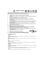
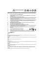
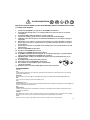
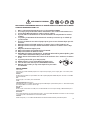
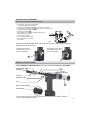
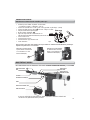
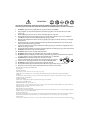
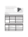
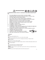
SAFETY INSTRUCTIONS :
TO INSURE PROPER FUNCTIONING AND SAFE OPERATION READ THIS MANUAL CAREFULLY BEFORE SETTING UP OR
OPERATING THE FACOM Y.135F TOOL.
1. DO NOT use this tool in a manner other than that recommended by FACOM.
2. Always wear eye protection when using or when near a tool that is in use.
3. This tool is NOT designed for use in explosive atmospheres.
4. Inspect tool for damage before connecting to air supply including all air connections.
5. Trained personnel must perform tool repair and/or maintenance at the prescribed intervals.
6. Disconnect the air supply when adjusting, servicing or removing any part of the tool.
7. Keep fi ngers off the trigger when connecting the air supply or if the air supply fails.
8. Keep fi ngers away from the front of the tool when connecting the air supply or setting rivets.
9. DO NOT point the tool at anyone.
10. DO NOT operate tool with the nose housing removed.
11. DO NOT operate tool without the Defl ector or Collector.
12. DO NOT modify the tool in any way. Modifi cation will make void any applicable warranties
and could result in damage to the tool or physical injury to the user.
13. DO NOT look into the tool from the front or the back during use or when connected to air supply.
14. The operating pressure must not exceed 100 psi (6.9 bar).
15. DO NOT direct tool exhaust towards anyone.
16. Wash hands if exposed to hydraulic fl uid or lubricant.
17. Keep hair, fi ngers and loose clothing away from moving parts of the tool.
I
I
I
I
I
I
I
I
I
I
I
I
I
I
I
I
I
I
I
I
I
BAR
5
6,2
7
0
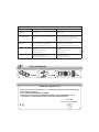
SAFETY DATA
First Aid:
SKIN:
Remove contaminated clothing and shoes and wipe excess from skin. Flush skin with water, then wash with soap and water.
If irritation occurs, get medical attention.
INGESTION:
Do not cause a vomiting. In general, no treatment is necessary unless large quantities of product are ingested.
However, get medical attention.
EYES:
Flush with water. If irritation occurs, get medical attention.
Fire:
FLASH POINT: 390°F/198.9°C
Material will fl oat and can be re-ignited on the surface of water. Use water fog "alcohol foam" dry chemical or carbon dioxide (CO2) to
extinguish fl ames. Do not use a direct stream of water.
Environment:
SPILLAGE:
Soak up residue with an absorbent such as clay, sand or other suitable material. Place in a non-leaking container and seal tightly for
proper disposal.
HANDLING:
Wash with soap and water before eating, drinking, smoking, applying cosmetics or using toilet. Properly dispose of leather articles such as
shoes or belts that cannot be decontaminated. Use in a well ventilated area.
STORAGE:
Store in a cool, dry place with adequate ventilation. Keep away from open fl ames and high temperatures.

11
EN
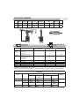
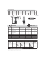
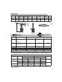
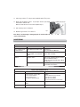
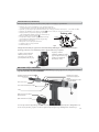
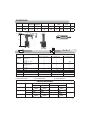
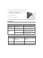
SPECIFICATIONS TECHNIQUES
Rivet type Material (Body – Mandrel) Rivet diameter
(*) 3,0 – 3,2 mm (1/8”) (*) 4,0 mm (5/32”) (**) 4,8 mm (3/16”)
Open end Al – Al
& MultiGrip Al – St/SS
St – St
SS - SS , Mo – St/SS (¤)
Closed end Al – Al
Al – St/SS/Cu – St
St – St
SS – SS
LSR Rivets Al – Al
HR™ Rivets St - St (**)
T-Rivet Al – St
Self Plugger Str – St
Ultragrip Al – Al/St-St/SS-SS - -
Use Y.135F028 instead of Y.135F027 (installed) when using 7/64” (2.8 mm) - 5/32” (4.0 mm).
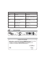
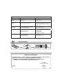
Stroke Pulling
Force
Operating
pressure
Max.
pressure
Air
Consumption
Air supply Noise Level
dB(A)
Vibration
Level
Weight
mm N bar bar l/min l/min Pressure Power m/s
2
kg
18 9400 5 - 6,2 6,9 70 150 88 99 < 2,5 1,31
ª
ª
79
▲
▲
▲
▲
▲
▲
A
C
B
A = B + C
£nÊ
{ääÊ
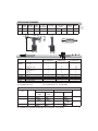
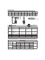
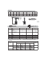
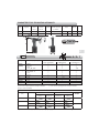
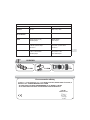
NOSEPIECES
Rivet diameter
(mm)
Open end CLOSED END HR RIVET JAW PUSHER
Steel
mandrel
Auminium
mandrel
Aluminium body Steel body
2,8 / 3,0 / 3,2
Y.135FE30 Y.135FE30 Y.135F028
4,0
Y.135FE40 Y.135FE40
--- -
Y.135F027
4,8
Y.135FE48 Y.135FE48
Al: Aluminum, St: Steel, SS: Stainless Steel, Cu: Cooper, Mo: Monel
(*) Use Y.135F028 Jaw pusher set up. (**)Use Y.135F027 Jaw pusher set up. (¤) Exclude MultiGrip

12
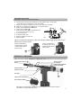
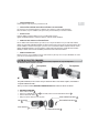
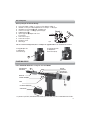
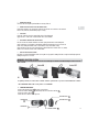
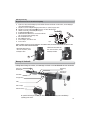
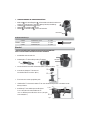
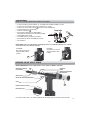
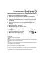
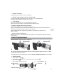
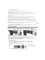
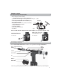
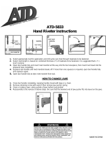
Basic Tool Operation
Before operating the tool check the following:
● Inspect tool for damage or leaking oil – do not use tool if it is damaged or leaking oil.
● Check that correct nosepiece is fitted and tightened to 60 - 65 in-lbs [6.8 – 7.3 N.m] torque.
● Check that the nose housing nut 10 is tight – hand tighten only.
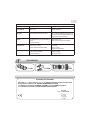
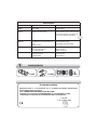
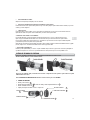
● Connect tool to air supply – see air supply requirements (fig.A).
● Fit Mandrel Collector 11 .
● Open air supply valve by sliding VA on side of tool
(see note below).
● Insert rivet into nosepiece.
● Position rivet in work piece.
● Pull trigger to set rivet.
● Release trigger
! Note: The Y.135F has an VA (Open-Shut) valve for switching the air supply ON and OFF to save air when the tool is not in use.
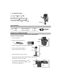
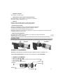
FRONT END SERVICE
!! Note: UNPLUG AIR SUPPLY while servicing front-end to avoid INJURY.
Air Supply ON: Open valve
by sliding VA in the
direction shown (up).
Air Supply OFF: Close Valve
by sliding VA in the
direction shown (down).
VA
NOSE HOUSING NUT 10
NOSE HOUSING
WRENCH FLAT
JAW GUIDE LOCK MOTION
O-RING
JAW GUIDE
PULLING HEAD
JAW GUIDE LOCK
HOUSING ADAPTER
PULLING HEAD LOCKING TEETH
JAW GUIDE TEETH
For optimum tool performance, Front-End maintenance should be performed regularly as per the “Preventative Maintenance Schedule”.
11
-!8ªªM
Dry air
fi g.A

13
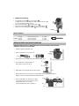
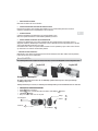
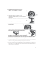
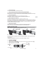
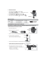
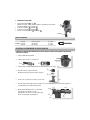
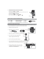
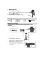
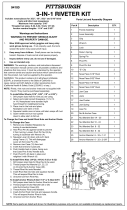
MANDREL COLLECTOR SYSTEM
For safety purposes, removing the Collector from the tool automatically turns the MCS suction OFF. Refi tting the Collector turns the
MCS suction ON.
CLEANING THE COLLECTOR SILENCER
For optimum performance, the Collector Silencer should be cleaned at regular intervals as per the“Preventative Maintenance Schedule”.
! Note: UNPLUG AIR SUPPLY while servicing Collector to avoid INJURY. !
1. CLEAN THE COLLECTOR :
• Remove and empty the Collector A by turning counterclockwise.
• Remove the Collector End Nut B (17 mm wrench) and remove the Collector End Cap C .
• Remove the Collector Silencer D .
• Clean and remove debris from all components.
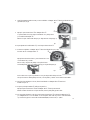
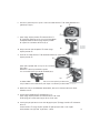
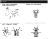
1. REMOVE NOSE HOUSING:
Unscrew the Nose Housing Nut by hand and slide Nose Housing off the tool.
2. REMOVE JAW GUIDE TO ACCESS JAWS AND INTERNAL PARTS:
Pull back the Jaw Guide Lock to disengage the Jaw Guide Lock teeth and unscrew and remove the Jaw Guide.
Remove Jaws, Jaw Pusher, and Jaw Pusher Spring for servicing.
3. CLEAN PARTS:
Clean Jaws, Jaw Guide, Jaw Pusher, Spring and thread area of the Pulling Head.
Apply Seal Lube to outside surface of Jaws and inside surface of the Jaw Guide.
4. REASSEMBLY OF INTERNAL PARTS AND JAW GUIDE:
Place the Jaws into the Jaw Guide and slide the Jaw Pusher Spring and Jaw Pusher into the Pulling Head.
Apply a small amount of Seal Lubricant to the Pulling Head threads and Jaw Guide Lock teeth. Screw the Jaw
Guide onto the Pulling Head until the teeth on the Jaw Guide Lock stop the Jaw Guide rotating.
Apply Jaw lubricant to the Jaw area by submerging the assembled Jaw Guide into Jaw lube about 1 in. (25mm).
Clean off excess Jaw Lube from the outside of the Jaw Guide.
5. REINSTALL NOSE HOUSING ASSEMBLY:
Refi t the Nose Housing and Hand-tighten the Nose Housing Nut securely against the O-Ring. If the Nut is not tightened suffi ciently against the
O-Ring there may be a loss of suction.
EN
Suction ON
Suction OFF
COLLECTOR END CAP C
COLLECTOR END NUT B
COLLECTOR BODY
A
COLLECTOR END E
COLLECTOR SILENCER D

14
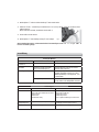
2. RE-ASSEMBLE THE COLLECTOR :
• Secure Collector End E to Collector Body F .
Use a screwdriver or similar tool to hold the
Collector End in place during re-assembly (see picture below).
• Place the Collector Silencer D onto the Collector End E .
• Place Collector End Cap C on Collector Body End E .
• Install and tighten Collector End Nut D on Collector End E .
TORQUE REQUIREMENTS
Y.135FE30 Nosepiece for rivet Ø 3,0 / 3,2 mm 6,8 - 7,3 N.m
Y.135FKE Y.135FE40 Nosepiece for rivet Ø 4,0 mm 6,8 - 7,3 N.m
Y.135FE48 Nosepiece for rivet Ø 4,8 mm 6,8 - 7,3 N.m
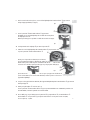
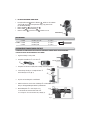
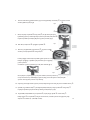
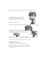
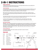
HYDRAULIC OIL CHARGING PROCEDURE
IMPORTANT. TOOL MUST BE DISCONNECTED FROM THE AIR SUPPLY. USE ONLY APPROVED
HYDRAULIC OIL SPECIFIED IN THIS MANUAL.
1. Disconnect from air supply.
2. Remove Nose Housing
➀ and Collector ➁.
3. Remove four Socket Head Cap Screws using 4mm Hex-Key wrench (Fig. 1).
4. Turn tool upside down and remove Chamber
➂.
Then pull out Air Piston Assembly
➃. (Fig. 2)
5. Drain the oil from the tool into a waste oil container.
6. Clean the dirt off the Air Piston Assembly
➃ and inner Chamber ➂ with a clean rag.
Apply a thin layer of Seal Lube to inner Chamber.
7. Loosen Jaw Guide
➄ approximately 3 full turns or a 0.12’’
(3 mm) gap and loosen Fill Screw
➅ approximately 3 - 3½ full
turns or a 0.14’’ (3.6 mm) gap (Fig. 3).
a
c
le
an
r
ag
Fig. 2
SCREWDRIVER
VIS CHc M4
Fig. 1
➀
➁
➂
➃
14
Fig. 3
3 mm
3,6 mm
➄
➅
F

15
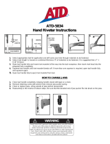
8. Secure the tool upside down again and pour hydraulic oil into Sleeve Lower ➆ to the level of the Backup Ring
(white part)
➇. (Fig. 4)
9. Push Air Piston Assembly
➃ into Sleeve Lower ➆ to half-way point so that
dirty hydraulic oil and air bubbles will come out from the loosened Fill Screw
➅.
Hold Air Piston Assembly until no more oil or bubbles come out. (Fig. 5)
10. Loosely tighten Fill Screw
➅ and pull out Air Piston Assembly ➃.
11. For more hydraulic oil into Sleeve Lower
➆ to the level of the Backup Ring and push Air Piston Assembly ➇ into Sleeve Lower ➆.
Push Air Piston inwards then outwards 5-6 times in a slow, constant motion.
Then pull it out and check for bubbles rising to the oil surface.
If there are still bubbles, repeat the procedure until there are no more bubbles (Fig. 6).
It may be necessary to repeat this procedure 2-3 times to bleed all bubbles from the oil.
If after 3 attempts there are still bubbles in the oil, go back to No.5 and start again by draining the hydraulic oil.
12. When there are no more bubbles in the oil, top off the hydraulic oil in the Sleeve Lower (51) to the level of the Backup Ring
➇.
13. Make sure the Jaw Guide
➄ is loose (see No.7).
Push the Air Piston Assembly
➃ into the Sleeve Lower ➆ to the half-way point.
While holding the Air Piston at the half-way point, replace the Nose Housing and hand tighten.
14. With a clean rag, wipe off any oil on the Air Piston Assembly
➃, Handle Lower Assembly ➈ and Sleeve Lower ➆.
Put Chamber
➂ over Air Piston Assembly ➃ then turn the tool upright and tighten the four Socket Head Cap Screws (CHc)
to a Torque of 46 - 51 in-lbs (5.2 – 5.8 N.m).
Ab
l
➇
iSl L
EN
EN
EN
EN
Fig. 4
➇
➆
Fig. 5
l
es (F
ig
. 6)
.
➆
➇
Fig. 6
➃
➆

16
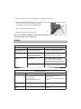
15. Remove the Nose Housing ➀, and tighten the Jaw Guide ➄ by hand until it stops.
16. Loosen the Fill Screw
➅ approximately 3 - 3½ full turns or a 0.14’’ (3.6 mm) gap to allow excess hydraulic oil
and bubbles to escape.
When no more oil comes out, tighten the Fill Screw (Fig. 7).
17. Wipe off any dirt and oil on the tool.
18. Replace the Nose Housing
➀ and Collector ➁.
Note: During assembly and disassembly, do not allow any metal swarf or dirt into the Hydraulic
Oil and inner Chamber.
MAINTENANCE
th H d li
Fig. 7
➅
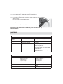
PREVENTATIVE MAINTENANCE SCHEDULE
ITEM ACTION FREQUENCY
Clean and lubricate Front
End of tool
See “Front End Service” 1 x per day or 5,000 rivet settings.
Inspect jaws Look for broken jaws and
damage or wear on jaw teeth.
During “Front End Service” or when jaws
slip on mandrel.
Collector Empty Collector When the quantity of stored spent
Mandrels starts to interfere with
mandrels entering the Collector.
(Storage quantity depends on rivet – approx. 50-70
3/16” (4.8 mm) rivets).
Clean Collector Silencer Once a week or when suction will not pull spent
mandrels into the Collector.
TROUBLESHOOTING
SYMPTOM PROBABLE CAUSE REMEDY
TOOL FAILS TO OPERATE Tool not connected to air supply.
VA Valve is in “OFF” position.
Insuffi cient air pressure.
Air pressure is too high.
Tool is low on hydraulic fl uid.
Connect to recommended air supply source.
Slide VA Valve to ON position.
Adjust air supply pressure.
Adjust air supply pressure.
Service tool by qualifi ed service personnel.
TOOL NOT RETURNING Possible jam due to debris in Nose Housing. Perform “Front End Service” and check for debris
or damage.
TOOL LOSING STROKE Tool low on hydraulic fl uid. Service tool by qualifi ed service personnel.

17
TROUBLESHOOTING
SYMPTOM PROBABLE CAUSE REMEDY
JAWS SLIPPING ON MANDRELS Jaws dirty or need lubrication.
Jaws worn.
Clean and lube jaws.
Replace jaws.
RIVET FAILS TO INSERT INTO
NOSEPIECE
Incorrect nosepiece.
Shear ring stuck in hole of nosepiece.
Install correct nosepiece.
Remove shear ring, check for the correct
Nosepiece and review application parameters to
ensure proper riveting.
RIVET MANDREL DOES NOT
BREAK
Rivet not fully set.
Mandrel break load requirement too high.
Insuffi cient air pressure.
Repeat stroke required, or change rivet.
Upgrade tool.
Adjust air supply pressure to recommended level.
SUCTION NOT WORKING Tool not connected to air supply.
Collector not tight or missing.
Mandrel path blocked.
Connect to recommended air supply source.
Check Collector.
Clear mandrel path.
LOW VACUUM Dirty Silencer.
Collector is full of mandrels.
Insuffi cient air pressure.
Clean or change Silencer.
Discard the mandrels.
Adjust air supply pressure.
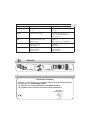
SPARE PARTS
EN
Y.135FKE Y.135FKM Y.135FB
CE Declaration of Conformity
WE, FACOM S.A.S., 6/8 RUE GUSTAVE EIFFEL - BP 99 - 91 423 MORANGIS CEDEX FRANCE, DECLARE UNDER OUR OWN RESPONSIBILITY
THAT THE PRODUCT Y.135F – FACOM PNEUMATIC RIVETER
- IS IN CONFORMITY WITH THE «MACHINERY” DIRECTIVE 98/37/EC ANNEXE I, II, III AND V
- AND IS IN CONFORMITY WITH THE PROVISIONS OF THE HARMONISED EUROPEAN
STANDARD EN 792-6
01.03.2009
FACOM Quality Manager
Page is loading ...
Page is loading ...
Page is loading ...
Page is loading ...
Page is loading ...
Page is loading ...
Page is loading ...
Page is loading ...
Page is loading ...
Page is loading ...
Page is loading ...
Page is loading ...
Page is loading ...
Page is loading ...
Page is loading ...
Page is loading ...
Page is loading ...
Page is loading ...
Page is loading ...
Page is loading ...
Page is loading ...
Page is loading ...
Page is loading ...
Page is loading ...
Page is loading ...
Page is loading ...
Page is loading ...
Page is loading ...
Page is loading ...
Page is loading ...
Page is loading ...
Page is loading ...
Page is loading ...
Page is loading ...
Page is loading ...
Page is loading ...
Page is loading ...
Page is loading ...
Page is loading ...
Page is loading ...
Page is loading ...
Page is loading ...
Page is loading ...
Page is loading ...
Page is loading ...
Page is loading ...
Page is loading ...
Page is loading ...

66
En France, pour tous renseignements techniques sur l'outillage à main, téléphonez au : 01 64 54 45 14
BELGIQUE
LUXEMBOURG
FACOM Belgie B.V.B.A.
Egide Walschaertsstraat 14-16
2800 MECHELEN
BELGIQUE
✆
: +32 (0) 15 47 39 35
Fax : +32 (0) 15 47 39 71
NETHERLANDS
FACOM Gereedschappen BV
Martinus Nijhofflaan 2
2624 ES DELFT
P.O. BOX 1007. 2600 BA Delft
NETHERLANDS
✆
: 0800 236 236 2
Fax : 0800 237 60 20
DANMARK
FINLAND
ISLAND
NORGE
SVERIGE
FACOM NORDEN
Nordre Strandvej 119B
3150 HELLEBÆK
DENMARK
✆
: +45 49 76 27 77
Fax : +45 49 76 27 66
SINGAPORE
FAR EAST
FACOM TOOLS FAR EAST
N° 25 Senoko South Road
Woodlands East Industrial Estate
Singapore 758081
SINGAPORE
✆
: (65) 6752 2001
Fax : (65) 6752 2697
DEUTSCHLAND
FACOM GmbH
Otto-Hahn-Straße 9
42369 Wuppertal
DEUTSCHLAND
✆
: +49 202 69 819-329
Fax : +49 202 69 819-350
SUISSE
ÖSTERREICH
MAGYARORSZAG
ČESKÁ REP.
FACOM WERKZEUGE GMBH
Ringstrasse 14
8600 DÜBENDORF
SUISSE
✆
: 41 44 802 8093
Fax : 41 44 802 8091
ESPAÑA
PORTUGAL
FACOM Herramientas S.L.
Poligono industrial de Vallecas
C/Luis 1°, s/n-Nave 95 - 2°Pl.
28031 Madrid
ESPAÑA
✆
: +34 91 778 21 13
Fax : + 34 91 380 65 33
UNITED
KINGDOM
EIRE
FACOM-UK
Europa view
SHEFFIELD BUSINESS PARK
ENGLAND
✆
: (44) 114 244 8883
Fax : (44) 114 273 9038
ITALIA
SWK Utensilerie S.r.l.
Via Volta 3
21020 Monvalle (VA)
ITALIA
✆
: (0332) 790 381
Fax : (0332) 790 307
POLSKA
FACOM Tools Polska Sp. zo.o.
ul.Modlińska 190
03-119 Warszawa
POLSKA
✆
: (48 22) 510-3627
Fax : (48 22) 510-3656
FRANCE
&
INTERNATIONAL
FACOM S.A.S.
6-8, rue Gustave Eiffel B.P.99
F-91423 Morangis cedex
FRANCE
✆
: 01 64 54 45 45
Fax : 01 69 09 60 93
http:/ /www.facom.com
Europa link
SHEFFIELD S9 1 XH
Stanley Deutschland GmbH
-
 1
1
-
 2
2
-
 3
3
-
 4
4
-
 5
5
-
 6
6
-
 7
7
-
 8
8
-
 9
9
-
 10
10
-
 11
11
-
 12
12
-
 13
13
-
 14
14
-
 15
15
-
 16
16
-
 17
17
-
 18
18
-
 19
19
-
 20
20
-
 21
21
-
 22
22
-
 23
23
-
 24
24
-
 25
25
-
 26
26
-
 27
27
-
 28
28
-
 29
29
-
 30
30
-
 31
31
-
 32
32
-
 33
33
-
 34
34
-
 35
35
-
 36
36
-
 37
37
-
 38
38
-
 39
39
-
 40
40
-
 41
41
-
 42
42
-
 43
43
-
 44
44
-
 45
45
-
 46
46
-
 47
47
-
 48
48
-
 49
49
-
 50
50
-
 51
51
-
 52
52
-
 53
53
-
 54
54
-
 55
55
-
 56
56
-
 57
57
-
 58
58
-
 59
59
-
 60
60
-
 61
61
-
 62
62
-
 63
63
-
 64
64
-
 65
65
-
 66
66


Facom Y 135F Owner's manual
- Category
- Power tools
- Type
- Owner's manual
- This manual is also suitable for
Ask a question and I''ll find the answer in the document
Finding information in a document is now easier with AI
in other languages
- italiano: Facom Y 135F Manuale del proprietario
- français: Facom Y 135F Le manuel du propriétaire
- español: Facom Y 135F El manual del propietario
- Deutsch: Facom Y 135F Bedienungsanleitung
- Nederlands: Facom Y 135F de handleiding
- dansk: Facom Y 135F Brugervejledning
- polski: Facom Y 135F Instrukcja obsługi
Related papers
Other documents
-
 FASTEN-PRO 1210 Owner's manual
-
 ATD Tools ATD-5833 User manual
-
Harbor Freight Tools 3_in_1 User manual
-
 FASTEN-PRO 94100 Owner's manual
-
 Malco 2in1 Operating instructions
-
 ATD Tools ATD-5834 Operating instructions
-
Campbell Hausfeld Air PoweredRivet Gun User manual
-
 Arconic MARSON MP-4V User manual
-
 Performance Tool W9069 Rivet Gun Drill Adapter Owner's manual
-
Power Fist 8843708 Owner's manual


