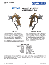
Binks Trophy AA1600 & AA4400 Owner's manual

Category
Paint Sprayer
Type
Owner's manual

This manual is also suitable for

TROPHY AA 4400
HVLP OR LVMP AIR-ASSIST
AIRLESS SPRAY GUNS
Twist tip versions
4400-HT0000 HVLP
4400-LT0000 LVMP
Flat tip versions
4400-HF0000 HVLP AA10 AIR CAP
4400-H10000 HVLP AA10+ AIR CAP
4400-H20000 HVLP 9X-H+ AIR CAP
4400-LF0000 LVMP 9X-L AIR CAP
The following instructions provide the necessary
information for the proper operation and preventive
maintenance of your new TROPHY AA Air-Assist Airless
Spray Gun.
Please read and understand all information in this
document in order to get the maximum performance
from your new TROPHY AA spray gun.
With your new TROPHY AA spray gun, the paint or other
material to be sprayed is primarily atomized as it passes
through the carbide tip. The air cap will also add a
secondary atomization, based on its conguration. This
is done by utilizing a separate air supply, to the gun.
You may also control the pattern size using the spreader
valve. This dual atomization and shaping produces an
exceptionally ne and even spray pattern. The result
of this spray pattern is an even nish that lends itself
to products that need an exceptionally ne nish with
reduced overspray and VOC emissions.
SPECIFICATIONS
Maximum uid pressure: 303 bar [4,400 psi]
Maximum air inlet pressure: 7 bar [105 psi]
Gun Body material: Forged Aluminum
Fluid Path material: Stainless Steel
Fluid Seat Material: Tungsten Carbide
Fluid inlet connection: 1/4" NPS (m)
Air inlet connection: 1/4" BSP / NPS (m)
77-3131-R4 (5/2019) 1 / 16 www.carlisleft.com
EN
SERVICE MANUAL
DJ Hasselschwert
(Vice President:
Global Product Development)
16430 N. Scottsdale Rd.
Scottsdale, AZ 85254
4-3193R-1
11-Jul-17
Signed for and on behalf of
Carlisle Fluid Technologies:
Machinery Directive 2006/42/EC
ATEX Directive 2014/34/EU
by complying with the following statutory documents and harmonized standards:
EN ISO 12100:2010 Safety of Machinery - General Principles for Design
BS EN 1953:2013 Atomising and spraying equipment for coating materials - Safety requirements
EN 13463-1:2009 Non electrical equipment for use in potentially explosive atmospheres - Basic methods and requirements
Providing all conditions of safe use / installation stated within the product manuals have been complied with and also installed
in accordance with any applicable local codes of practice.
The object of the declaration described above is in conformity with the relevant Union harmonisation
legislation:
This Declaration of Conformity
/incorporation is issued under the sole
responsiblility of the manufacturer:
Carlisle Fluid Technologies Inc.
16430 N. Scottsdale Rd.
Scottsdale, AZ 85254
EU Declaration of Conformity
II 2 G X
Notified body details and role:
Element Materials Technology. WN8 9PN UK
Lodging of Technical file
Protection Level:
Product Description/Object of Declaration:
Solvent and Water based Materials
Zone 1
Suitable for use in hazardous area:
This Product is designed for use with:
AIR-ASSIST
AIRLESS SPRAY GUN
EN
77-3131-R4 (5/2019)2 / 16www.carlisleft.com
LOCK OUT / TAG-OUT
Failure to de-energize, disconnect, lock out and tag-out all power
sources before performing equipment maintenance could cause
serious injury or death.
OPERATOR TRAINING
All personnel must be trained before operating finishing
equipment.
EQUIPMENT MISUSE HAZARD
Equipment misuse can cause the equipment to rupture,
malfunction, or start unexpectedly and result in serious injury.
PROJECTILE HAZARD
You may be injured by venting liquids or gases that are released
under pressure, or flying debris.
PINCH POINT HAZARD
Moving parts can crush and cut. Pinch points are basically any
areas where there are moving parts.
INSPECT THE EQUIPMENT DAILY
Inspect the equipment for worn or broken parts on a daily basis.
Do not operate the equipment if you are uncertain about its
condition.
In this part sheet, the words WARNING, CAUTION and NOTE are used to
emphasize important safety information as follows:
Hazards or unsafe practices which
could result in minor personal injury,
product or property damage.
!
CAUTION
Hazards or unsafe practices which
could result in severe personal
injury, death or substantial property
damage.
!
WARNING
Important installation, operation or
maintenance information.
NOTE
Read the following warnings before using this equipment.
READ THE MANUAL
Before operating finishing equipment, read and understand all
safety, operation and maintenance information provided in the
operation manual.
WEAR SAFETY GLASSES
Failure to wear safety glasses with side shields could result in
serious eye injury or blindness.
NEVER MODIFY THE EQUIPMENT
Do not modify the equipment unless the manufacturer provides
written approval.
IT IS THE RESPONSIBILITY OF THE EMPLOYER TO PROVIDE THIS INFORMATION TO THE OPERATOR OF THE EQUIPMENT.
FOR FURTHER SAFETY INFORMATION REGARDING THIS EQUIPMENT, SEE THE GENERAL EQUIPMENT SAFETY BOOKLET (77-5300).
KNOW WHERE AND HOW TO SHUT OFF THE EQUIPMENT
IN CASE OF AN EMERGENCY
PRESSURE RELIEF PROCEDURE
Always follow the pressure relief procedure in the equipment
instruction manual.
NOISE HAZARD
You may be injured by loud noise. Hearing protection may be
required when using this equipment.
STATIC CHARGE
Fluid may develop a static charge that must be dissipated through
proper grounding of the equipment, objects to be sprayed and all
other electrically conductive objects in the dispensing area. Improper
grounding or sparks can cause a hazardous condition and result in
fire, explosion or electric shock and other serious injury.
WEAR RESPIRATOR
Toxic fumes can cause serious injury or death if inhaled.
Wear a respirator as recommended by the fluid and solvent
manufacturer’s Safety Data Sheet.
TOXIC FLUID & FUMES
Hazardous fluid or toxic fumes can cause serious injury or death if
splashed in the eyes or on the skin, inhaled, injected or
swallowed. LEARN and KNOW the specific hazards or the fluids
you are using.
KEEP EQUIPMENT GUARDS IN PLACE
Do not operate the equipment if the safety devices have been
removed.
!
WARNING
AUTOMATIC EQUIPMENT
Automatic equipment may start suddenly without warning.
FIRE AND EXPLOSION HAZARD
Improper equipment grounding, poor ventilation, open flame or
sparks can cause a hazardous condition and result in fire or
explosion and serious injury.
MEDICAL ALERT
Any injury caused by high pressure liquid can be serious. If you
are injured or even suspect an injury:
Go to an emergency room immediately.
Tell the doctor you suspect an injection injury.
Show the doctor this medical information or the medical alert
card provided with your airless spray equipment.
Tell the doctor what kind of fluid you were spraying or
dispensing.
GET IMMEDIATE MEDICAL ATTENTION
To prevent contact with the fluid, please note the following:
Never point the gun/valve at anyone or any part of the body.
Never put hand or fingers over the spray tip.
Never attempt to stop or deflect fluid leaks with your hand,
body, glove or rag.
Always have the tip guard on the spray gun before spraying.
Always ensure that the gun trigger safety operates before
spraying.
EN
77-3131-R4 (5/2019) 3 / 16 www.carlisleft.com
INSTALLATION
Before proceeding, make sure trigger lock is engaged.
NOTE
1. Connect your high-pressure uid hose to the gun uid
inlet and tighten securely.
2. Connect your air hose to the gun air connection and
tighten securely.
3. Slowly increase air to the pump to obtain a uid pressure
at the gun’s lower end of the pressure range. A typical
starting uid pressure is 70 bar [1000 psi]. Actual starting
pressure points may be higher or lower and be dependent
on the type of pump used, the type of material sprayed,
and the spray gun itself.
4. Using the control knob of the gun air regulator at the air
control, set the gun shaping air pressure at 0 bar [0 psi].
5. To test the spraying pattern, spray a sample piece of wood
or cardboard with a fast pass about 30cm [1 ft] away
from the surface. The results of the test will allow you to
determine the uniformity of the particle size and spraying
pattern.
6. If the spraying pattern develops tails or is not uniform,
gradually increase the air pressure as necessary to
develop a uniform spraying pattern. 1 bar [14 psi] is the
maximum inlet air pressure for HVLP air caps, or use 1.4-
2.8 bar [20-40 psi] inlet air pressure for LVMP air caps.
7. If the pattern is still unacceptable, you may gradually
increase the uid pump air pressure in 0.7 bar [10 psi]
increments using the uid pump air regulator control
knob. Repeat step 6, as needed.
8. Once the quality of spray is acceptable, begin spraying.
If the spraying rate is too slow to keep up with the
production line speed, or if the quantity of material
sprayed is inadequate for acceptable coverage, repeat
step 7, until desired pattern and material quantity is
achieved. If the maximum uid pressure is reached before
the required material coverage and spraying speed are
achieved, you may need to switch to a different uid tip.
FLUID TIP SELECTION
Factors to consider in selecting a uid tip for an air-assist
airless spray gun include:
• The size of the parts being sprayed.
• The production line speed
• The material ow rate and lm thickness.
• The viscosity of the material applied
• The type of material applied.
• The quality of atomization of the coating required.
The selection of a uid tip necessary to perform a specic
spraying job is best determined through a combination of
experimentation and expert advice from your material and
equipment suppliers.
Air Supply
Oil & Water
Extractor
MX Pump
Fluid
Filter
Air
Control
Trophy AA
Spray Gun
SPRAY PATTERN ADJUSTMENT
Turn the spreader valve knob indicated below
counterclockwise to decrease the pattern size;
clockwise to increase pattern size.
Spray pattern adjustment
control knob
For HVLP spray, spray pattern adjustment feature requires
1 bar [14 psi] maximum of air inlet pressure.
For LVMP spray, spray pattern adjustment requires
approximately 1.4-2.8 bar [20-40 psi] of air inlet pressure.
Higher fluid pressures will require a higher air inlet pressure
to accommodate pattern adjustment.
NOTE
FLUID HOSES
Air-assist airless spray guns operate at uid pressures higher
than operating pressures of air spray guns. As a result, when
operating an air-assist airless spray gun, it is critical to select
the appropriate uid hose that is rated for the pressure range
at which the airless gun is operated.
The spray gun must be earthed to dissipate any electrostatic charges which may be created by fluid or air flows.
This can be achieved through the spray gun mounting, or conductive air/fluid hoses. Electrical bond from the spray gun to earth
should be checked and a resistance of less than 10
6
Ohms is required.
!
WARNING
EN
77-3131-R4 (5/2019)4 / 16www.carlisleft.com
GENERAL TROUBLESHOOTING
PROBLEM CAUSE REMEDY
Fluid leaking from needle
packing
Worn needle packing or needle shaft Replace air valve & uid needle assembly, item 5.
Loose needle packing Tighten packing nut gradually until leak stops.
Fluid leaking from the front of
the gun
Worn or damaged needle ball Replace air valve & uid needle assembly, item 5.
Worn seat assembly Replace uid nozzle, item 9.
Fluid in air passages Spray tip seal leaking Tighten air cap & nozzle guard assembly, item 11 or 13.
Replace carbide tip seal. RS-5000-K5 or RS-5000-K10
Leaking around uid seat Tighten or replace uid nozzle, item 9.
Fluid slow to shut off Fluid buildup on needle assembly Clean or replace air valve & uid needle assembly, item 5.
No uid output when gun is
triggered
Tip orice is plugged Flat tips - Turn off uid supply. Relieve pressure into a closed
earth-grounded container. Engage trigger safety. Remove air
cap/nozzle guard assembly and spray tip. Clean or replace
the spray tip, item 12.
Twist tips – Rotate twist tip 180° within the air cap, then
spray into a closed earth-grounded container to try to clear
tip of any debris. If that fails, turn off uid supply. Engage
trigger safety. Remove air cap/nozzle guard assembly and
spray tip. Clean or replace the twist tip, item 10.
Needle is damaged or broken Turn off uid supply. Relieve pressure into a closed earth-
grounded container. Engage trigger safety. Replace air valve
& uid needle assembly, item 5.
Fluid lter is plugged Turn off uid supply. Relieve pressure into a closed-grounded
container. Engage trigger safety. Turn off air supply to pump
and relieve uid pressure from pump using bypass valve on
pump. Very slowly loosen the uid hose connection at the
gun to relieve any pressure in the hose. Remove the uid
hose. Using two wrenches, one to hold the uid tube in
place, and the other to remove the nut. Open the uid lter,
and clean or replace the lter element, item 17e.
Fluid hose is plugged Turn off uid supply. Relieve pressure into a closed-grounded
container. Engage trigger safety. Turn off air supply to pump
and relieve uid pressure from pump using bypass valve on
pump. Very slowly loosen the uid hose connection at the
gun to relieve any pressure in the hose. Remove the hose
and clear obstruction, or replace hose.
Needle Packing Nut
Trigger Safety
Fluid Filter
EN
77-3131-R4 (5/2019) 5 / 16 www.carlisleft.com
TROUBLESHOOTING SPRAY PERFORMANCE
Always engage trigger lock and relieve fluid pressure.
!
CAUTION
PROBLEM CAUSE CORRECTION
Heavy top or bottom pattern. Material build-up on air cap, plugged
horn holes, center holes or jets.
Soak cap or tip in suitable solvent and thoroughly
clean.
Material build-up on uid tip exterior or
partially plugged uid tip.
Replace uid tip or air cap if necessary.
Fluid tip or cap dirty or damaged. Replace uid tip or air cap if necessary.
Heavy right or left side pattern. Left or right side horn holes plugged. Soak cap or tip in suitable solvent and thoroughly
clean.
Dirt or damage on left or right side of
uid tip exterior.
Replace uid tip or air cap if necessary.
Remedies for the top-heavy, bottom-heavy, right-heavy and left-heavy patterns.
Determine if the obstruction is on the air cap or the uid tip. Do this by making a test spray pattern. Then, rotate the air cap and tip one-half
turn and spray another pattern. If the defect is inverted, obstruction is on the air cap. Clean the air cap as previously instructed. Also check for
dried paint just inside the cap center hole opening, remove by washing with solvent.
If the defect is not inverted, it is on the uid tip. Clean tip. If problem persists, renew tip.
Heavy center pattern. Pattern adjustment valve set too low. Turn out counter clockwise to achieve correct
pattern.
Too much material. Reduce uid pressure.
Material too thick. Thin to correct consistency.
Atomizing air pressure too low. Increase air pressure.
Intermittent or 'uttering' spray fan. Fluid tip not seated correctly in gun
head.
Remove uid tip, clean components, check
cone seating on tip and gun for damage or
contamination.
Partially obstructed uid passage or
hose.
Clean or replace.
EN
77-3131-R4 (5/2019)6 / 16www.carlisleft.com
TROUBLESHOOTING SPRAY PERFORMANCE
Always engage trigger lock and relieve fluid pressure.
!
CAUTION
PROBLEM CAUSE CORRECTION
Split spray pattern. Not enough material ow. Increase uid ow by changing uid tip size, or increase uid
pressure.
Excessive bounce-back. Too much atomization air pressure. Reduce air pressure.
Gun too far from surface. Check distance.
Runs and sags. Too much uid ow. Adjust gun or reduce uid pressure.
Material too thin. Mix properly or apply light coats/reduce uid ow.
Gun tilted at an angle. Mount gun at right angle to work.
Thin, sandy coarse nish
drying before it ows out.
Gun too far from surface. Check distance.
Too much air pressure. Reduce air pressure and check spray pattern.
Fluid ow too low. Increase uid ow by changing uid tip size, supply pressure.
EN
77-3131-R4 (5/2019) 7 / 16 www.carlisleft.com
TROPHY AA 4400 SPRAY GUN ASSEMBLIES
1
2
3
4
5
6
7
8
9
12
11
10
13
16
14
15
17
17e
18
19
17f
17b
3a
3b
3c
3d
9a
17d
17c
17g
17a
4a
4b
4c
4d
4e
20
(SOLD SEPARATELY)
(SOLD SEPARATELY)
EN
77-3131-R4 (5/2019)8 / 16www.carlisleft.com
PARTS LIST
ITEM
NO.
PART NO. DESCRIPTION
4400-
HF0000
FLAT TIP
QTY.
4400-
H10000
FLAT TIP
QTY.
4400-
H20000
FLAT TIP
QTY.
4400-
LF0000
FLAT TIP
QTY.
4400-
HT0000
TWIST TIP
QTY.
4400-
LT0000
TWIST TIP
QTY.
1 54-6008 AIR VALVE HOUSING 1 1 1 1 1 1
2 54-5935-K5 NEEDLE RETURN SPRING KIT (MULTI-PACK) 1 1 1 1 1 1
3 54-6131-K SPINDLE SEAL & SPRING KIT 1 1 1 1 1 1
3a REAR SEAL 1 1 1 1 1 1
3b AIR VALVE SPRING 1 1 1 1 1 1
3c VALVE SEAL 1 1 1 1 1 1
3d FRONT SEAL 1 1 1 1 1 1
4 54-5815 SPREADER VALVE ASSEMBLY 1 1 1 1 1 1
4a VALVE STEM 1 1 1 1 1 1
4d VALVE BODY 1 1 1 1 1 1
4c SN-71X-K2
l
O-RING (MULTI-PACK) 1 1 1 1 1 1
4b
l
PIN 1 1 1 1 1 1
4e
l
SNAP RING 1 1 1 1 1 1
5 54-5937 AIR VALVE & FLUID NEEDLE ASSEMBLY 1 1 1 1 1 1
6 54-6114 TRIGGER NUT 1 1 1 1 1 1
7 54-6115 TRIGGER SCREW 1 1 1 1 1 1
8
SPA-71-K5
SPA-71-K10
BAFFLE PLATE (MULTI-PACK) 1 1 1 1 1 1
9
54-5799-K FLUID NOZZLE & GASKET (FLAT TIP) 1 1 1 1
54-5832-K FLUID NOZZLE & GASKET (TWIST TIP) 1 1
9a
SPA-98-K5 GASKET (MULTI-PACK)
SPA-98-K10 GASKET (MULTI-PACK)
10 SEE PAGE 10 REVERSABILE TWIST TIP
11
54-5924-K HVLP TWIST TIP AIR CAP ASSEMBLY 1
54-5925-K LVMP TWIST TIP AIR CAP ASSEMBLY 1
12
SEE PAGE 10 FLAT TIP ASSEMBLY
SEE PAGE 10 FINE FINISH FLAT TIP ASSEMBLY
13
54-5878-K 9X-H+ AIR CAP ASSEMBLY (4400-HF0000) 1
54-5890-K AA10 AIR CAP ASSEMBLY (4400-H10000) 1
54-6030-K AA10+ AIR CAP ASSEMBLY (4400-H20000) 1
54-5797-K 9X-L AIR CAP ASSEMBLY (4400-LF0000) 1
14 SN-9-K3 AIR INLET (MULTI-PACK) 1 1 1 1 1 1
15 SLOTTED ROUND HEAD SCREW, 1/4" - 20 x 1/2", S.S. 1 1 1 1 1 1
16 54-6019
TRIGGER 1 1 1 1 1 1
17 54-6015 FLUID TUBE ASSEMBLY 1 1 1 1 1 1
17a FLUID TUBE ADAPTER 1 1 1 1 1 1
17b 54-5896-K5 FLUID TUBE RETAINER (MULTI-PACK) 1 1 1 1 1 1
17c 54-5899 FERRULE NUT 1 1 1 1 1 1
17d 54-6017 FILTER BRACKET 1 1 1 1 1 1
17e 54-1835
p
FLUID FILTER, 100 MESH 1 1 1 1 1 1
17f
54-4726-K
DISC FILTER BODY, 1/4" NPS (M) 1 1 1 1 1 1
17g DISC FILTER RETAINER 1 1 1 1 1 1
18 54-5897 JIC #5 FLUID INLET FITTING (SOLD SEPARATELY)
19 72-2360 SWIVEL ADAPTER, 1/4" NPS M X F (SOLD SEPARATELY)
20 SPN-7 TOOL 1 1 1 1 1 1
Parts are included within the following packing kits:
l Parts are included in kit: GTI-428-K5
ALTERNATE ITEMS (SOLD SEPERATELY):
p 54-1836 FLUID FILTER, 60 MESH
54-6018 TRIGGER, SHORT PULL
EN
77-3131-R4 (5/2019) 9 / 16 www.carlisleft.com
FLAT TIP AIRCAPS
REVERSIBLE TWIST TIP AIRCAPS
TROPHY AA 4400 AIR CAP ASSEMBLIES
4
5
6
3
5
6
4
2
2
3
1
1
HVLP LVMP
54-5924-K 54-5925-K
ITEM
NO.
PART NO. DESCRIPTION AA10 9X-L
1 see pages 14-15 TWIST TIP
2 54-7539-K2 TWIST TIP BRACE 1 1
3 TWIST TIP AIR CAP COLOR BLACK SILVER
4 54-5930 RETAINING SCREW 1 1
5 TWIST TIP RETAINING RING 1 1
6 TWIST TIP GUARD 1 1
TEST AIR CAP KITS: 54-5932-K
HVLP LVMP
54-6030-K 54-5890-K 54-5878-K 54-5795-K 54-5797-K
ITEM
NO.
PART NO. DESCRIPTION AA10+ AA10 9X-H+ 9X-H 9X-L
1
SEAL REMOVAL TOOL
2 see pages 14-15
REPLACABLE TIP SEAL
3 see pages 14-15
RS SPRAY TIP
4
AIR CAP COLOR
BLUE BROWN BLACK SILVER SILVER
5 54-6029
RETAINING RING WITH SEALS
1 1 1 1 1
6 54-5794
FLAT TIP GUARD
1 1 1 1 1
TEST AIR CAP KITS:
54-6036 54-5836-K
AIR CAP INDEXER
SPA-70-K10
SOLD SEPARATELY
EN
77-3131-R4 (5/2019)10 / 16www.carlisleft.com
MAINTENANCE AND CLEANING
Maintenance of air-assist airless spray guns
includes three areas:
• uid tip wear and replacement
• lubrication
• cleaning of the gun
FLUID TIPS
Operating an air-assist airless spray gun with a worn
uid tip will result in increased usage of spraying
material and therefore, hazardous air pollutants. For
example, an increase in the diameter of a tip from .4 to
.5mm [0.015 to 0.021 in] due to wear can result in
up to a 100 percent increase in material consumption
and cost. To prevent waste in spraying material and
non-value-added costs, a maintenance schedule that
includes uid tip inspection and replacement, should be
established.
LUBRICATION
Proper lubrication is essential for optimum spray gun
performance. Lubrication allows the equipment to
operate easily and correctly. The spray gun should be
lubricated after each cleaning. The points that need
lubrication during the maintenance of air-assist airless
spray guns include the uid needle packing and trigger
pivot point.
Never immerse the entire gun in solvent or thinners. Some
gun parts will lose their lubricative film and wear more
quickly. Additionally, solvents may carry impurities
throughout the gun body and allow them to clog small
air and fluid passages.
!
CAUTION
CLEANING
The following steps summarize the procedure for
cleaning air- assist airless spray guns:
1. Turn off the air supply to the gun.
2. Turn off air supply to the pump and relieve uid
pressure. This may be accomplished by opening the
bypass valve, if so equipped.
3. Place the material suction tube into a solvent
container. If the pump is directly immersed in
material, remove the pump and immerse it in a
container containing solvent.
4. Engage the gun trigger safety switch into the locked
position (move down).
5. Remove the uid or twist tip and place it in a closed
solvent container.
Use only compatible solvents that are identified as approved
for cleaning and wash-off use.
NOTE
6. Adjust the pump air supply regulator to its lowest
level (turning knob counter-clockwise).
7. Release the gun trigger safety switch into the
unlocked position (move up).
8. Turn on the air supply to the pump and close the
bypass valve, if so equipped.
9. Slowly adjust the pump air supply regulator until the
pump begins to cycle (turning knob clockwise).
Failure to reduce pump air supply pressure or to use a closed
container can result in material “bounce-back”.
Material “bounce back” can cause injury and damage.
!
WARNING
During cleaning, the gun may only be sprayed into a closed
earth-grounded container, never flush the gun into the air or
spray booth.
NOTE
10. Trigger the gun into a closed earth-grounded
container until the uid runs clear.
11. Using a rag dampened with solvent, wipe the
exterior surface of the gun. Additionally, some
solvents are prohibited from being used for cleaning.
The operator must take care to use only approved
cleaning solvents for equipment cleaning. These
materials are clearly labeled as approved for
cleaning and wash off operations. If the operator
has any question on selecting appropriate cleaning
solvents, the operator should consult a supervisor or
plant environmental staff.
EN
77-3131-R4 (5/2019) 11 / 16 www.carlisleft.com
MAINTENANCE — DISASSEMBLY
14mm
4
3b
2
3a
1
16mm
5
6mm
20
3c 20
3d
12
13
9
8
19mm
14 15
14mm
17
16mm
8mm
3c
7
6
16
77-3130-R1.0
Page #
MAINTENANCE
Disassembly
EN
77-3131-R4 (5/2019)12 / 16www.carlisleft.com
MAINTENANCE — ASSEMBLY
3d
20
3c
20
5
6mm
6-7 Nm
[5-6 ft-lbs]
1
20
3a
3b
2
16mm
8mm
7 16
6
14mm
4
17
16mm
49-62 Nm
[11-14 ft-lbs]
8
9
19mm
MAINTENANCE
Assembly
17-20 Nm
[13-15 ft-lbs]
3d
20
3c
20
5
6mm
6-7 Nm
[5-6 ft-lbs]
1
20
3a
3b
2
16mm
8mm
7 16
6
14mm
4
17
16mm
49-62 Nm
[11-14 ft-lbs]
8
9
19mm
MAINTENANCE
Assembly
17-20 Nm
[13-15 ft-lbs]
3d
20
3c
20
5
6mm
6-7 Nm
[5-6 ft-lbs]
1
20
3a
3b
2
16mm
8mm
7 16
6
14mm
4
17
16mm
49-62 Nm
[11-14 ft-lbs]
8
9
19mm
MAINTENANCE
Assembly
17-20 Nm
[13-15 ft-lbs]
3d
20
3c
20
5
6mm
6-7 Nm
[5-6 ft-lbs]
1
20
3a
3b
2
16mm
8mm
7 16
6
14mm
4
17
16mm
49-62 Nm
[11-14 ft-lbs]
8
9
19mm
MAINTENANCE
Assembly
17-20 Nm
[13-15 ft-lbs]
12
13
80-98 Nm
[18-22 ft-lbs]
14 15
14mm
MAINTENANCE
Assembly
12
13
80-98 Nm
[18-22 ft-lbs]
14 15
14mm
MAINTENANCE
Assembly
EN
77-3131-R4 (5/2019) 13 / 16 www.carlisleft.com
TROPHY AA TIP OFFERING
STANDARD TIP SIZES OFFERED
PART
NUMBER
ORIFICE
FAN WIDTH
*
CAPACITY
**
RS-0702
.18mm
[.007in]
50mm [2in]
106 CC
[.028 GPM]
RS-0704 100mm [4in]
RS-0706 150mm [6in]
RS-0708 200mm [8in]
RS-0902
.23mm
[.009in]
50mm [2in]
148 CC
[.039 GPM]
RS-0904 100mm [4in]
RS-0906 150mm [6in]
RS-0908 200mm [8in]
RS-0910 250mm [10in]
RS-0912 300mm [12in]
RS-1104
.28mm
[.011in]
100mm [4in]
227 CC
[.060 GPM]
RS-1106 150mm [6in]
RS-1108 200mm [8in]
RS-1110 250mm [10in]
RS-1112 300mm [12in]
RS-1114 350mm [14in]
RS-1304
.33mm
[.013in]
100mm [4in]
341 CC
[.090 GPM]
RS-1306 150mm [6in]
RS-1308 200mm [8in]
RS-1310 250mm [10in]
RS-1312 300mm [12in]
RS-1314 350mm [14in]
RS-1316 400mm [16in]
RS-1506
.38mm
[.015in]
150mm [6in]
454 CC
[.120 GPM]
RS-1508 200mm [8in]
RS-1510 250mm [10in]
RS-1512 300mm [12in]
RS-1514 350mm [14in]
RS-1516 400mm [16in]
RS-1518 450mm [18in]
RS-1706
.43mm
[.017in]
150mm [6in]
606 CC
[.160 GPM]
RS-1708 200mm [8in]
RS-1710 250mm [10in]
RS-1712 300mm [12in]
RS-1714 350mm [14in]
RS-1716 400mm [16in]
RS-1718 450mm [18in]
RS-1816
.46mm
[.018in]
400mm [16in]
681 CC
[.180 GPM]
STANDARD TIP SIZES OFFERED
PART
NUMBER
ORIFICE
FAN WIDTH
*
CAPACITY
**
RS-1906
.48mm
[.019in]
150mm [6in]
719 CC
[.190 GPM]
RS-1908 200mm [8in]
RS-1910 250mm [10in]
RS-1912 300mm [12in]
RS-1914 350mm [14in]
RS-1916 400mm [16in]
RS-1918 450mm [18in]
RS-2110
.53mm
[.021in]
250mm [10in]
908 CC
[.240 GPM]
RS-2112 300mm [12in]
RS-2114 350mm [14in]
RS-2116 400mm [16in]
RS-2118 450mm [18in]
RS-2410
.61mm
[.024in]
250mm [10in]
1173 CC
[.310 GPM]
RS-2412 300mm [12in]
RS-2414 350mm [14in]
RS-2416 400mm [16in]
RS-2418 450mm [18in]
RS-2710
.69mm
[.027in]
250mm [10in]
1457 CC
[.385 GPM]
RS-2712 300mm [12in]
RS-2714 350mm [14in]
RS-2716 400mm [16in]
RS-2718 450mm [18in]
* Fan width based on 69 bar [1000 PSI] of water sprayed
at 300mm [12in] from surface. Actual results may vary
based on material sprayed.
** Capacity based on 34 bar [500 PSI] of uid pressure
using water pressure.
REPLACEMENT TIP SEALS FOR STANDARD STYLES:
RS-5000-K5 Multi-pack of 5 pieces
RS-5000-K10 Multi-pack of 10 pieces
EN
77-3131-R4 (5/2019)14 / 16www.carlisleft.com
TROPHY AA TIP OFFERING
FINE FINISH TIP SIZES OFFERED
PART
NUMBER
ORIFICE
FAN WIDTH
*
CAPACITY
**
REPLACEABLE
SEAL
RS-0909-F
.23mm
[.009in]
225mm [9in]
148 CC
[.039 GPM]
RS-5858-K5
RS-0911-F 280mm [11in]
RS-1109-F
.28mm
[.011in]
225mm [9in]
227 CC
[.060 GPM]
RS-5859-K5
RS-1111-F 280mm [11in]
RS-1113-F 330mm [13in]
RS-1115-F 380mm [15in]
RS-1309-F
.33mm
[.013in]
225mm [9in]
341 CC
[.090 GPM]
RS-5860-K5
RS-1311-F 280mm [11in]
RS-1313-F 330mm [13in]
RS-1315-F 380mm [15in]
RS-1509-F
.38mm
[.015in]
225mm [9in]
454 CC
[.120 GPM]
RS-5861-K5
RS-1511-F 280mm [11in]
RS-1513-F 330mm [13in]
RS-1515-F 380mm [15in]
RS-1517-F 430mm [17in]
RS-1709-F
.43mm
[.017in]
225mm [9in]
606 CC
[.160 GPM]
RS-5862-K5
RS-1711-F 280mm [11in]
RS-1713-F 330mm [13in]
RS-1715-F 380mm [15in]
RS-1717-F 430mm [17in]
* Fan width based on 69 bar [1000 PSI] of water sprayed at 300mm
[12in] from surface. Actual results may vary based on material
sprayed.
** Capacity based on 34 bar [500 PSI] of uid pressure using water
pressure.
TWIST TIP SIZES OFFERED
PART
NUMBER
ORIFICE
FAN WIDTH
***
CAPACITY
****
9-211-75 .28mm [.011in]
100mm
[4in]
454 CC [.120 GPM]
9-213-75 .33mm [.013in] 681 CC [.180 GPM]
9-215-75 .38mm [.015in] 908 CC [.240 GPM]
9-217-75 .43mm [.017in] 1173 CC [.310 GPM]
9-307-75 .18mm [.007in]
150mm
[6in]
189 CC [.050 GPM]
9-309-75 .23mm [.009in] 341 CC [.090 GPM]
9-311-75 .28mm [.011in] 454 CC [.120 GPM]
9-313-75 .33mm [.013in] 681 CC [.180 GPM]
9-315-75 .38mm [.015in] 908 CC [.240 GPM]
9-317-75 .43mm [.017in] 1173 CC [.310 GPM]
9-319-75 .48mm [.019in] 1457 CC [.385 GPM]
9-409-75 .23mm [.009in]
200mm
[8in]
341 CC [.090 GPM]
9-411-75 .28mm [.011in] 454 CC [.120 GPM]
9-413-75 .33mm [.013in] 681 CC [.180 GPM]
9-415-75 .38mm [.015in] 908 CC [.240 GPM]
9-417-75 .43mm [.017in] 1173 CC [.310 GPM]
9-419-75 .48mm [.019in] 1457 CC [.385 GPM]
9-421-75 .53mm [.021in] 1779 CC [.470 GPM]
9-435-75 .89mm [.035n] 4959 CC [1.31 GPM]
9-509-75 .23mm [.009in]
250mm [10in]
341 CC [.090 GPM]
9-511-75 .28mm [.011in] 454 CC [.120 GPM]
9-513-75 .33mm [.013in] 681 CC [.180 GPM]
9-515-75 .38mm [.015in] 908 CC [.240 GPM]
9-517-75 .43mm [.017in] 1173 CC [.310 GPM]
9-519-75 .48mm [.019in] 1457 CC [.385 GPM]
9-521-75 .53mm [.021in] 1779 CC [.470 GPM]
9-523-75 .58mm [.023in] 2158 CC [.57 GPM]
9-525-75 .64mm [.025in] 2536 CC [.670 GPM]
9-611-75 .28mm [.011in]
300mm
[12in]
454 CC [.120 GPM]
9-613-75 .33mm [.013in] 681 CC [.180 GPM]
9-615-75 .38mm [.015in] 908 CC [.240 GPM]
9-617-75 .43mm [.017in] 1173 CC [.310 GPM]
9-619-75 .48mm [.019in] 1457 CC [.385 GPM]
9-621-75 .53mm [.021in] 1779 CC [.470 GPM]
9-623-75 .58mm [.023in] 2158 CC [.57 GPM]
9-625-75 .64mm [.025in] 2536 CC [.670 GPM]
9-627-75 .69mm [.027in] 2801 CC [.740 GPM]
9-631-75 .79mm [.031in] 3899 CC [1.03 GPM]
9-635-75 .89mm [.035n] 4959 CC [1.31 GPM]
9-713-75 .33mm [.013in]
350mm
[14in]
681 CC [.180 GPM]
9-715-75 .38mm [.015in] 908 CC [.240 GPM]
9-717-75 .43mm [.017in] 1173 CC [.310 GPM]
*** Fan width based on 152 bar [2200 PSI] of latex sprayed at
300mm [12in] from surface. Actual results may vary based
on material sprayed.
**** Capacity based on 152 bar [2200 PSI] of uid pressure
using latex.
EN
77-3131-R4 (5/2019) 15 / 16 www.carlisleft.com
EN
77-3131-R4 (5/2019)16 / 16www.carlisleft.com
WARRANTY POLICY
This product is covered by Carlisle Fluid Technologies’ materials and workmanship limited warranty.
The use of any parts or accessories, from a source other than Carlisle Fluid Technologies,
will void all warranties. Failure to reasonably follow any maintenance guidance provided
may invalidate any warranty.
For specic warranty information please contact Carlisle Fluid Technologies.
For technical assistance or to locate an authorized distributor,
contact one of our international sales and customer support locations.
Region Industrial/Automotive Automotive Renishing
Americas
Tel: 1-800-992-4657 Tel: 1-800-445-3988
Fax: 1-888-246-5732 Fax: 1-800-445-6643
Europe, Africa,
Middle East, India
Tel: +44 (0)1202 571 111
Fax: +44 (0)1202 573 488
China
Tel: +8621-3373 0108
Fax: +8621-3373 0308
Japan
Tel: +81 45 785 6421
Fax: +81 45 785 6517
Australia
Tel: +61 (0) 2 8525 7555
Fax: +61 (0) 2 8525 7575
Carlisle Fluid Technologies is a global leader in innovative nishing technologies.
Carlisle Fluid Technologies reserves the right to modify equipment specications without prior notice.
DeVilbiss
®
, Ransburg
®
, ms
®
, BGK
®
, and Binks
®
are registered trademarks of Carlisle Fluid Technologies, Inc.
©2019 Carlisle Fluid Technologies, Inc.
All rights reserved.
For the latest information about our products, visit www.carlisleft.com
  • Page 1 1
  • Page 2 2
  • Page 3 3
  • Page 4 4
  • Page 5 5
  • Page 6 6
  • Page 7 7
  • Page 8 8
  • Page 9 9
  • Page 10 10
  • Page 11 11
  • Page 12 12
  • Page 13 13
  • Page 14 14
  • Page 15 15
  • Page 16 16

Binks Trophy AA1600 & AA4400 Owner's manual

Category
Paint Sprayer
Type
Owner's manual
This manual is also suitable for

Ask a question and I''ll find the answer in the document

Finding information in a document is now easier with AI