6
Making the Electrical
Connections
WARNING
TO AVOID POSSIBLE ELECTRICAL SHOCK, BE
SURE ELECTRICITY IS TURNED OFF AT THE
MAIN FUSE BOX BEFORE WIRING.
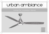
(Figure 11) Motor to eceiver electrical connec-
tions: Connect the black wire from the fan to
black wire marked "TO MOTOR L". Connect
the white wire from the fan to the white wire
marked "TO MOTOR N" from the receiver.
2.
(Figure 11) Receiver to house supply wires
electrical connections: Connect the black (hot)
wire from the ceiling to the black wire marked
"AC in L" from he receiver. Connect the white
(neutral) wire from the ceiling to the white wire
marked "AC in N" from the receiver. Secure
the wire connections with the plastic wire
connecting nuts provided.
(Figure 11) If your outlet box has a ground
wire (green or bare copper) connect it to the fan
ground wires; otherwise connect the hanging
bracket ground wire to the mounting bracket.
Secure the wire connection with a plastic nut
provided. After connecting the wires spread
them apart so that the green and white wires are
on one side of the outlet box and black and blue
wires are on the other side. Carefully tuck the
wire connections up into the outlet box.
Connect the blue wire from the fan to the blue
wire marked "For Light" from the receiver.
Secure the wire connections with the plastic
wire connecting nuts provided.
3.
4.
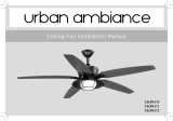
Insert the receiver into the mounting bracket
with the flat side of the receiver facing the
ceiling as Figure 10.
1.
If you feel you do not have enough electrical
wiring knowledge or experience, have your fan
installed by a licensed electrician.
Follow the steps below to connect the fan to your
household wiring. Use the wire nuts supplied with
your fan. Secure the wire nuts with electrical tape.
Make sure there are no loose strands or
connections.
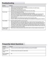
This remote control unit is equipped with 16 code
combinations to prevent possible interference
from or to other remote units. The frequency
switches on your receiver and transmitter have
been preset at the factory. Please recheck to make
sure the switches on the transmitter and the
receiver are set to the same position, any
combination of settings will operate the fan as
long as the transmitterand receiver are set to the
same position. Select “D” or “ON” in the
frequency switches to control the light dimmer or
ON/OFF function based on your light bulbs
(Factory setting is on “ON”). For use with
incandescent bulbs, use the “D” setting for full range
dimming. For fans that use Fluorescent bulbs, use the
“ON” setting for the light to have ON/OFF functions
only. (Figure 9).
Figure 9
Figure 10
Receiver
Ceiling
Mounting
Bracket
Frequency Switch
CAUTION
DO NOT USE WITH WALL LIGHT DIMMER
SWITCH.
NOTE
FAN MUST BE INSTALLED AT A MAXIMUM
DISTANCE OF 20 FEET FROM THE TRANSMIT-
TING UNIT FOR PROPER SIGNAL TRANSMIS-
SION BETWEEN THE TRANSMITTING UNIT
AND THE FAN'S RECEIVING UNIT.
ON