Page is loading ...

SUBURBAN MANUFACTURING COMPANY
Post Office Box
399
Dayton, Tennessee
37321
a
substdrary
a(
AIRXCEL, !nc.
SUBURBAN GAS FURNACES
INSTALLATION INSTRUCTIONS
FOR MODELS
SF-20F
SF-25F SF-30F SF-35F
The design of the furnace has been listed for installation in recreational vehicles only.
In
order for the furnace to operate
in
conformity
with generally accepted safety regulations, the installation instructions must be followed. Failure to comply with the installation
instructions will void the warranty on the furnace and any responsibility on the part of Suburban Manufacturing Company.
The furnace was inspected before it left the factory. If any parts are found to bedamaged, do not install the furnace. Immediately contact
the transportation company and file a claim.
FOR YOUR SAFETY
WHAT TO DO IF YOU SMELL GAS:
Extinguish any open flame.
Evacuate all persons from the vehicle.
Shut off the gas supply at the gas
container or source.
Do not touch any electrical switch, or
use any phone or radio in the vehicle.
Do not start the vehicle's engine or
electric generator.
Contact the nearest gas supplier or
qualified service technician for repairs.
If you cannot reach a gas supplier or
qualified service technician, contact the
nearest fire department.
Do not turn on the gas supply until the
gas
leak(s) has been repaired.
This book contains instructions covering the operation and
maintenance of your furnace. Keep with unit at all times.
Should
you
require further information, contact your dealer or
nearest Suburban Service Center.
I
FOR YOUR SAFETY
1
DO NOT STORE OR USE GASOLINE OR
OTHER FLAMMABLE VAPORS AND
LIQUIDS IN THE
VICINITY OF THIS OR
WARNING! Improper installation,
adjustment, alteration, service or
maintenance can cause property damage,
personal injury or loss of life. Refer to the
installation instructions
and/or owners
manual provided with this appliance.
Installation and service must be
performed by a qualified installer, service
agency or the gas supplier.
WARNING! Be sure the furnace and all
1
ignition systems are "OFF" during any
type of refueling and while vehicle is
in
motion or being towed.
INSTALLATION INSTRUCTIONS
WARNING! Installation of this appliance must be made in accordancewith
the written instructions provided in this manual.
Noagent, representative
or employee of Suburban or other person has the authority to change,
modify or waive any provision of the instructions contained in this
manual.
CAUTION: In any installation in which the vent of this appliance can be
covered due to the construction of the RV or some special feature of the RV
such as slide out, pop-up etc. always insure that the appliance cannot be
operated by setting the thermostat to the positive "OFF" position and
shutting off all electrical and gas supply to the appliance. Never operate
furnace with vent covered.
These furnaces are designed and installed in such a manner as to be removable
NOTE:
These
furnaces
must
be installed
and vented
as
described
in
this
manual
only from within living area of the recreational vehicle.
so that the negative pressure created by the air circulating (return air) fan cannot
CAUTION: If possible, do not install the furnace to where the vent can be
affect the combustion air intake or venting of
any other apphance. It is imperative
covered or obstructed when any door on the trailer is opened. If this is not that the products of combustion be properlyvented to the almosphere and
t!iat all
possible, then the travel of the
door must be restricted in order to provide
combustion air supplied to burner be drawn from the outside atmosphere (See
a
6"
minimum clearance between the furnace vent and any door whenever Installing Vent Assembly)
the door is opened.
NOTE: Do not install the furnace with the vent facing toward
tha ionvard end of
NOTE- The exhaust temperature of this furnace could discolor or warp some the coach.
materials. You should verify that the material used on the coach door, panel, or
cover
will
not
discolor
or
warp
from
the
exhaust
temperature
whenever
any
door,
IMPORTANT-
If
this furnace is to be connected to a
common
duct systef:: also
panel, or cover is in the open position.
se~ing a cooling unit, a manual or automatic damper is required to prevent any
cold conditioned air from circulatina back into the furnace. Cold air
~assina over
CAUTION: Due to the differences in vinyl siding, this appliance should not
thefurnacecombustionchamberd~ring
theoperationof the coolinci unit carTresult
be installed on vinyl siding without first consulting with the manufacturer of
in the formation of condensation inside the furnace combustior: chamber This
the siding or cutting the siding away from the area around the appliance
condensation may promote corrosion and premature failure
of
the combustion
vent. chamber.
Form No. 2555-C

NOTE These furnaces shall be installed so the electrical components are
protected frorn water.
These furnaces are design certified for
propane1LP gas only. Do not attempt to
convert to natural gas.
Gas supply pressure tor purposes of input
adjustme~il
Minimum
-
11" W C
'
Maximum
-
13" WC
'
(W.C.'
-
Water Column).
In the U.S.A.. the installation of Ihe furnace must be
In accordance with local
codes and regulations. In the absence of local codes and regulations, refer to tlie
latest edition of:
1. Standard for
Recreat~onal Vehrcles ANSl A-1 19 2lNFPA 501 C
6.
Install vent assembly (See instrtlctions for installing vent
)
B.
IF
NOT
INSTALLED
AGAINST
OUTER
SKIN AND
-x-
DIMENSION
GREATER THAN
1-112"
1.
Determine "x" dimensron as illustrated in F~gure 2 Tube length for
"x"
dimension are charted. Special tubes, if needed, must be ordered.
2. Locate center lines for exhaust and intake lubes as shown Figure 1 Cut two
2-3:4" diameter holes through coacli wall for exliausl and intake. (See Figure 2.)
3.
Put furnace in place and secure furnace to cabmet.
4.
Uslng the two #I0 x 314 stainless screws provided. fasten to floor of coacli
tlirougti two holes provided in front plenum area of furnace cabinet. (See Figure
1
.1
1. Standard CANICSA-2240 Recreational Veli~cles
IF-20~ 1"
:ll
:::
0"
!\
318"
2.
CSA Standard CANICSA-2240
6
2-M86 Electrical Requirements for
SF-25F
l"
0" 0" 318"
Recreational Vehicles SF-30F
1"
0" 0"
0
0" 318"
3.
Standard CANICSA-2240 4.2-M86 Installation Requirements for Propane
SF.~~F
1,' 0 0" 0" 0" 318"
Appliances and Equ~pment in Recreational Vehicles.
2. National Fuel Gas Code
ANSl 2223 1
5
Install venl assembly (See ~nstruct~ons for Install~nq Vent
)
6
Rernstall cabinet front
3
Furnace must be electrically grounded In accordance w~lh the latest ed~tion of
4.
CANICGA-6149 Installation Codes
5.
Any applicable local codes and regulations.
the
Nat~onal Electrrcal Code ANSIINFPA No 70
-NOTE-
0"
MEANS TO SPACER BUMPS
Left Right Exhaust and
Model Front Srde
S~de Top Bottom Back Intake Tube
In Canada the furnace must be
lnslalled ~n accordance with
I
AHLt
2
There are two (2) methods described below for installing the furnace. Regardless
This unit is equipped with an electric igniter device that has an energy
consumption of
.1 amp
@
12 volts DC
of the method you choose, we require that a permanent opening be prov~ded in
theinteriorcabinetryof the coach directly
~n front of the furnace. Theopening must
allow
torfree, unobstructed removal of the furnace. This opening may be used as
a means of providing circulating return air to the furnace. Other openings may be
used as well. It is important that adequate return air be provided to assure normal
heating and operation
of the furnace. Failure to provide the minimum return air will
cause erratic furnace cycling Refer to
the chart shown below for minimum return
air requirements.
NOTE- Return air must be from within the
livinq area of the coach
CLEARANCE FROM DUCTS TO
COMBUSTIBLE MATERIAL
-
114" (See Figure
3)
RETURN AIR
-.
-.
-
-
INSTALLING THE FURNACE
Return Air Requirements
Model Minimum Free (unobstructed) Area
NOTE. Before installing the furnace
"X
dimension as illustrated in Figure 2 must
be determined.
SF-2OF125F/3OF/35F
1.
Locate the furnace near lengthwise center of the coach
2.
Choose a location for installation out of the way of wires, pipes, etc.. which
might interfere with the installation. Adhere to the minimum clearances from tlie
cabinet to combustible construction as listed in Table 2 Refer to Figure 3 for
illustration of furnace clearances.
NOTE: Side and top clearances may be
"0
for through the wall installations up to
a maximum of 3" wall thickness. (See Figure 1.)
55 Sq.
In
3.
When an appliance is installed d~reclly on carpeting, tile or other combustible
material, other than wood flooring, the appliance shall be installed on a metal or
wood panel extending the full width and depth of the appliance.
If
preferred, the
carpeting, tile or combustible materials, other than wood may be cut away the full
length and depth of
the appliance plus the appliance minimum clearances to
combustibles. (See Table
2.)
TABLE 1
4.
Determine "x" dimension as shown in Figure 2. The tubes supplied wlth the
furnace will accommodate an installation range for
"x" from 1-112"
-
3" If "x"
dimension is less than 1-112" or greater than 3". then special vent tubes as
charted in Figure
2
must be ordered.
WARNING! Do not alter. cut or otherwise modify
supplied
by Suburban. Doina so could result in inadequate intake of
I
combustion air or improper &ting of furnace exhaust.
.
5. After determining "x" dimension, complete the furnace installation as follows.
A. IF INSTALLED DIRECTLY AGAINST OUTER
SKIN OR
"X"
DIMENSION IS
0
-
1-112"
1.
Vent Kit 520597 must be ordered. Do not cut or alter the vent tubes supplied
with the furnace.
2.
Cut an opening through the inner wall 17-314 x
8".
Thls will allow the rear of the
furnace to be installed against the outer
skln of the coacli. (See Figure 1
.)
3.
Cut two 2-114'' diameter holes through the outer skin of the coach, as shown
in Figure 1
INSTALLING VENT ASSEMBLY
The vent outlet must be installed so it is in the same atmospheric pressure zone
as the combustion air intake. The exhaust and intake tubes must be installed from
the outside, pass through the RV skin and slide onto the furnace exhaust and
intake.
WARNING! Do not alter the vent assembly supplied with this furnace. Any
modifications will result inimproperinstallation which could causeunsafe
furnace operation.
CAUTION! Combustion air must not be drawn from the living area. All air for
combustion must
bedrawn from theoutside atmosphere. All exhaust gases
must be vented to the outside atmosphere
-
never inside the RV. Therefore,
it is essential to insure that the vent cap and tube assemblies are properly
installed.
1. Apply caulking to RV skin behind vent cap as shown in Figure
1.
Apply caulking
generously around perimeter of vent cap and across center as shown.
2. Insert intake tube through RV skin and slide it onto the furnace intake (See
Figure 2.) Minimum tube overlap of
112" is required.
3.
Insert venl cap exhaust tube through RV skin and slide it onto the furnace
exhaust (See Figure 2.) Minimum tube overlap of 1 114" is required.
4.
Attach vent cap assembly to outer skin of RV with the six
(6)
screws provided.
Do not install vent assembly upside down. The words "Suburban" and "Dayton,
Tenn." must be right side up.
CONNECTING GAS
SUPPLY
Connect the gas supply to the furnace at the manifold, following the suggestions
outlined below. It will be necessary to hold the flare fitting on the furnace manifold
when connecting or loosening gas line.
NOTE: The compound used on threaded joints must be resistant to liquefied
petroleum (LP) gas.
NOTE: The appliance must be disconnected from the gas supply piping system
during any pressure testing of that system at test pressure in excess of 112 PSIG.
The appliance must be isolated from the gas supply piping during any pressure
testing of the gas supply piping system at test pressure equal to or less than 112
PSIG.
1.
Connect gas line to the 318" elbow at the front of the furnace. (See Figure 1
.)
Some standards may require the use of a manual shut off valve in the gas line
external to the furnace cabinet
2.
In order to maintain a check of gas supplied pressure to the furnace, Sububan
advlses the installer to provide the 118" NPT plug tap for test gauge connection
immediately upstream of the gas supply connection to the furnace and that it be
readily accessible.
3.
After the furnace has been connected to the gas supply, all joints must be
checked for leaks.
WARNING! Nevercheck for leaks with an open
flan~r. Turn on the gas and
apply soapy water to all joints to see if bubbles are formed.
CONNECTING ELECTRICAL SUPPLY
4.
Put furnace in place, making sure that rear of furnace cabinet is as close to
CAUTION:
This
furnace
is
for
negative
ground
12
volt
D.C,
system
outer skin of coach as possible and still assure proper vent tube overlap. (See
only,
Do
not
anempt
to
alter
the
furnace
for
a
positive
ground
system
or
Installing Vent Assembly.) Secure furnace to cabinet. (See Figure 1
.)
connect the furnace directlv to 115 volts A.C. Damaae tofurnacecom~onent
-
5. Us~no the two #I0 x 314 stamless screws ~rovlded fasten furnace to floor of
Darts will occur.
coach
tkough the two holes provided in the frbnt area of furnace cabinet.
(See Figure 1
.)

Be sure all wiring to the furnace is of heavy enough gauge to keep the voltage
4. Inspect furnace, the venting, ducting and gas piping to furnace for obvious
drop through it to a minimum and to provide enough power for start-up surge No signs of deterioration. Correct any defects at once
12
gauge wire is recommended If any of the original wire that is supplled with the
appliance must be replaced, it must be replaced with type
105"
C or its
equivalent
Power supply connections are to be on the right side of the fuinace The wires are
-
color coded, red for positive
(+)
and yellow for negatlve (-).,This polarity must be
observed so the furnace motor will run the proper direction of rotation to insure
correct air delivery. (See wiring diagram
)
If the furnace power supply is to be from a converter, we recommend that the
converter system used to power the furnace be wired in parallel
w~th the battery
This will serve two purposes
1.
Provide a constant voltage supply lo the furnace
2. Filter any A C. spikes or volt surges
CONNECTING DUCTS TO FURNACE
The following duct requirements must be followed in order to assure proper
operation of the furnace:
A. The minimum open duct areas listed below must be maintained throughout
entire duct system
including
through register
NOTE: Ducts terminating in a dead air space (like holding tank
compartments) with no means for return air recirculation should not be
counted in the required duct area. Also ducts 2" in diameter or smaller
should not be counted in the required duct area.
8.
Make the duct connections at the furnace cabinet tight. Loose connections will
result in overheating of the component parts on the furnace and a reduction of the
heated air flow through the duct system.
C. Avoid making any sharp turns in the duct system. Sharp turns will increase the
static pressure in the plenum area and could cause the furnace to cycle.
D.
Avold making a lot of turns In the duct system The
straighter
the duct system.
,
the better the performance of the furnace
E. Maintain a minimum of 114" clearance where ducts pass through any
combust~ble construct~on, such as coach cabinetry (See Figure
3
)
NOTE UL
llsted duct materials can be
0
clearance
F. Do not install air boosters in the duct system. Such devices will cause the
furnace to cycle on limit and to have erratic sail switch operation.
NOTE. After installation of the furnace and duct system is completed, adjustments
must be made to obtain a temperature rise within the range specified on the
Rating Plate.
INSTALLING THERMOSTAT
Locate the room thermostat approximately
4-112 feet above the floor on an inside
bulkhead where it is not affected by heat from any source except room air.
Connect thermostat wiring to the blue wires on right side of furnace. (See wiring
diagram.)
PREVENTIVE MAINTENANCE
in which it was shipped from the factory or if the appliance is not used
solely for its intended purpose or if appliance is not maintained in
accordance with the instructions in this manual, then the risk of a fire
and/or the production of carbon monoxide exists which can cause
5.
lnspect combustion chamber for restrictions in exhaust or intake. It is
imperative that the flow of intake combustion air and the flow of exhaust gases
being expelled to the outside atmosphere not be obstructed. Any soot or loose
debris should be blown out using compressed air. (See Figure
6.)
6.
lnspect all gaskets. If any gaskets show signs of leakage or deterioration,
replace them Safe operation of the furnace depends on all gaskets being tight.
7.
lnspect return air inlet openings to the furnace. Remove any restrictions to
assure adequate air flow
You, as the ownerluser, should inspect the furnace monthly during the
heating season for presence of soot on vent. Operating the furnace under this
condition could lead to serious property damage, personal injury or loss of life. If
soot is observed on the vent, immediately shut the furnace down and contact a
qualified
service agency
Llsted below are several safety related items that you should follow during the
heatlng season to assure continued safe operation of the furnace.
1.
lnspect furnace venting Venting must be free of obstructions, void of soot, and
properly terminated to the atmosphere. (See Installing Vent Assembly.)
WARNING! Do not install screens over the vent for any reason. Screens
will become restricted and cause unsafe furnace operation. Accessories
are being marketed for RV products which we do not recommend. For
your safety, only factory authorized parts are to be used on your furnace.
2.
Periodically
inspect the vent for obstructions or presence of soot. Soot is
formed whenever
combustlon is incomplete. This is your visual warning that the
furnace is operating in an unsafe manner. If soot is present, immediately shut
furnace down and contact your dealer or a qualified service person
3.
Keep furnace clean. More frequent cleaning may be required due to excessive
lint from carpeting, bedding material, etc. It is imperative that control
compartments, burners and circulating air passageways of the appliance be kept
clean
4. The motor is permanently lubricated and requires no oiling.
5.
Keep the furnace area clear of any combustible materials, gasoline or other
flammable vapor and liquids
6.
Before operating furnace, check the location of the furnace vent to make sure
it will not be blocked by the opening of any door on the trailer. If it can be blocked.
do not operate the furnace with the door open.
7.
Do not restrict the flow of combustion air or the warm air circulation to the
furnace. To do so could cause personal injury
andlor death.
8.
Never operate the furnace
if
you smell gas. Do not assume that the smell of
gas in your RV is normal. Any time you detect the odor of gas, it is to be
considered life
threatening
and corrected immediately. Extinguish any open
flames including cigarettesand evacuate all persons from thevehicle. Shut off gas
supply at LP gas bottle (See safety notice on front cover of this manual.)
9.
Immediately shut furnace down and call a service agency if furnace cycles
erratically
or delays on ignition
WARNING! Should overheating occur, or the gas supply fail to shut off,
shut off the manual gas valve to the appliance before shutting off the
electrical supply.
10. Never attempt to repair damaged parts. Always have them replaced by a
qualified
service agency.
11. Never attempt to repair the furnace yourself. Seek the help of a qualified
service person.
12. Never restrict the ducting installed by your trailer manufacturer. To do so could
cause improper furnace operation.
13.
Do not install air boosters in the duct system. Such devices will cause the
furnace to cycle and to have erratic sail switch operation.
14. Clothing or other flammable material should not be placed on or near the
appliance
15.
Always follow the operating instructions. Do not deviate from the step-by-step
CAUTION: Label all wires
beforedisconnectingforservicing.
Proper polarity
procedures
must be observed so the furnace motor will run with the proper direction of
rotation to insure correct air delivery. (See wiring diagram).
16. Do not use this appliance
if
any part has been submerged under water.
Immediately call a qualified service technician to inspect the appliance and to
CAUTION: Label all wires prior to disconnection when servicing controls.
replace
any
part
of
the control system and
any
gas
control that has been
Wiring error can cause improper and dangerous furnace operation.
submerged under water.
Always verify proper operation of furnace after servicing.
Your furnace should be inspected by a qualified service agency yearly before
turning the furnace on. Particular attention should be given to the following items
1.
lnspect furnace installation and vent termination to be sure furnace is properly
secured in place (see Installation Instructions), that vent terminates to the
atmosphere, and that vent tubes overlap properly (see Installing Vent Assembly
)
2.
lnspect chamber and venting to assure that these components are physically
sound without holes or excessive corrosion and that the installation
andlor re-
installation is in accordance with Suburban's installation instructions. (Reference
installation manual supplied with furnace.)
WARNING! It is imperative that the products of combustion be properly
vented to atmosphere and that all combustion air supplied to burner be
drawn from outside atmosphere.
3.
Check the base on which furnace is mounted Be sure it is physically sound.
void of any sagging, deterioration, etc
17.
Whenconsidering add-on rooms, porch or patio, attention must be given to the
venting of your furnace. For your safety, do not terminate
furnace vent inside add-
on rooms, screen porch or onto patios. Doing so will result in products of
combustion being vented into the room or occupied areas.
18.
In any installation in which the vent of this appliance can be covered due to the
construction of the RV or some special feature of the RV such as slide out, pop-
up,
etc, always insure that the appliance cannot be operated by setting the
thermostat to the positive "OFF position and shutting off all electrical and gas
supply to the appliance. Never operate furnace with vent covered.
INSTALLATION AND REMOVAL OF UNIT
TO REMOVE
1.
Disconnect power supply at furnace
2.
Remove vent cap assembly.
3.
Disconnect gas connections

4.
Remove cabinet front (2 screws).
TO SHUT DOWN
5.
Remove t~e-down screw from center of unit and remove furnace from cabinet
1.
Set the thermostat to lowest settlng. then move lever to "OFF'. position.
TO INSTALL
2.
Turn manual shut off valve (if so equipped) to the "OFF position Do not force.
1. Slide unit into cabinet NOTE: Care must be taken in
routlng wlrlng to back of
cabinet and outside of cabinet
2.
Reinstall tie-down screw, securlng chamber assembly to cablnet
3.
Reinstall cabinet front.
4.
Connect gas line
5.
Check gas connections for leaks using a soap and water solution Correct any
gas leaks immediately.
6.
Reinstall vent cap assembly.
7.
Reconnect power supply.
OPERATING INSTRUCTIONS
WARNING! Do not operate furnace while vehicle is in motion or being
towed.
NOTE: During initial firing of this furnace, a burn-off of excess paint and oils
rema~ning from manufacturing process may cause "smoking" for
5
-
10 minutes
1.
Stop! Read Users Information Manual supplied with furnace
2.
Turn the manual valve (if so equipped) or the valve at the outside LP tank to
the "OFF" position. Do not force.
3.
Set thermostat above room temperature to begin blower operation. A slight
delay will occur before the blower comes on. Allow blower to run for
5
minutes for
combustion chamber purge cycle.
4.
After
5
minutes, move thermostat lever below room temperature. Blower will
remain on Wait approximately 2
mlnutes for blower to go off.
5.
Open manual shut-off valve (if so equipped) or the valve at the outslde LP tank.
Correct operating characteristics depend on the valve being positioned fully open.
Never
attemot to ooerate with a valve oartiallv closed. NOTE- This furnace is
ELECTRODE ADJUSTMENT
For
consistent
~gn~tlon of the burner.
11
IS
Important that the electrode be poslt~oned
properly over the top of the burner The electrode was set at the lactory for proper
~gnltlon and should not need further adjustment. however.
if
you should
experience
lnconslstent lgnltlon, reposlt~on electrode as follows
Equipment needed:
flashlight
black felt-tip pen
needle-nose pliers
rneasurlng tape
NOTE: Furnace must be removed (See instructions for removing unit.)
1. Remove burner lrom combustion chamber by removing six (6) screws which
attach the burner to the chamber and air baffles (plates).
2.
Locate the lance in relation to the burner ports for electrode positioning by:
a. Shine a flashlight into the burner venturi as illustrated. (Be sure flashlight
lens is against the end of the burner.)
b. Light will reflect off the lance
In the venturi of the burner and shine through
a portion of the two
(2)
rolls of burner ports in the top of the burner.
c. Using a black felt-tip pen, mark a line along top of burner 3/16" in back of
the lance and parallel with lance. Make an additional mark indicating the
center line of the lance. (See illustration.) Both marks will be used later as
reference marks; therefore, keep lines thin.
3.
Reassemble the burner.
4.
Adjust electrode so the electrode probe is positioned along the marked center
line of the burner lance and the tip of the electrode terminates 3/16" from the back
of the lance. (At the line marked in Step 2-c.) (See Figure
4.)
5.
IMPORTANT: Be sureelectrode probe maintains a 118" spark gap over the
burner as illustrated.
equipped
with a valbe shut-off switch, with swikh in "OFF position. Gas will not
6.
~~~~~t~ll the
furnace
into the
following
the instructions in the manual,
flow to burner nor will the furnace operate.
6.
Set thermostat lever to desired setting. If set above room temperature, blowel
will come on.
7.
Allow 30 seconds for main burner to light after blower comes on. This furnace
is equipped with an
ignltion device which automatically lights the burner Do not
try to light the burner by hand.
8. If burner does not light, repeat Steps
1
through
8
9.
If after three (3) attempts with no ignition, go to shut down and contact your
dealer or a local recreational vehicle service agency. Do not continue to cycle
furnace through thermostat in an attempt to get ignition. NOTE:
If
furnace should
lock out, the blower will go off in
5
minutes and remain off until unit is reset by
reactivating thermostat.
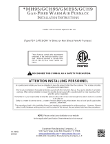
1
FRONT
Figure 1

SF-20F.
.
.
. .
. .
.
S<;2SF,~SF-30F2.-SF~35F.
ZF-42F.
.
STANOAKD dENT INSTALLATION
TRAILER SKIN
W
a
+
L
52
C1
+
'7
3
a
1
X
\-VENT CAP
-
-
.
-
.
-
-.
.-
"
DrHENslnN
-
_E~~~~~~~'~!.
+NE~ER INSTALL THE EXHAUST TUBE
0' TO 1 1/2. 520767 VITH LESS THAN
1
1/4' OVERLAP. OR
THE
ZtJTAYE TUBE YiTH LESS THAN
3'10...,
.
_
520768
~
~~~
112'
OVERLAP.
4
1/2' TO
7
I/?'
520769
7
I/?'
TO
9'
520551
LP.....
*STANDARD VENT ASSEMBLY FURNISHED YliH FURNACE SPECIAL EXTENSICN TUBES, IF
NEEDED. MUST BE ORDERED SEPARATELY EXTENXION <IT: GOHE VlTH COMPLETE
INSTALLATION INS
IKUCTlONS.
Figure
2
HAINTAIN A 1/4' INCH CLEARANCE
VIiERE DUCTS PASS THROUGH
A CLBINET VCLL UL LISTED DUCT
Figure
3
Figure
4
Figure
5

TO CLEAN THE CHAMBER. THE FURNACE MUST BE RiMOVED FROM
THE CABINET AND THE MANIFOLD BLOWER ASSEMBLY AND CONTROLS
REMOVED
LEAVING
THE
CHAMBLK
m,
as
SHOWN
USING
COMPRESSED AIR. BLOW THROUGH THE CHSMBER, AS 5IIOWI.I BY
ARROVS, TO REMOVE SOOT
UR LUUSE DEBRIS
Figure
6
Figure
7
Figure
8
3'2
Figure
9

REPLACEMENT PARTS LIST
Only factory authorized parts are to be used
.
Do not altempt to repair defective
Item
NO
.
1
When
orderlng repa~rpansfrom your dealsr a Suburban Sewlce Center. ordlslr~butor
.
always glve the Iollow~ng ~nlormal~on
1 . Pan Number (Not llem No
)
2
.
Pan Descr~pl~on
3 . Model and Serlal Number ol lurnace
4 . Number of Pans Requ~red
Description
Cablnet Fronl Assembly ................
Thermostal .....................
Screw 810
x
314 (2 Requ~red)
....
Screw ir8
x
318 (2 Requ~red)
...
. .
......
Cabinet Assembly (SF-~OFISF-~~F; SF-~O~ only]
...............
Cablnet Assembly (SF-35F only)
.
...........................
Cover Duct
Collar
.
Duct .............................
Nut 8-32 Keps
..........................
Manifold Assembly Complete
....................
........................
Screw #8
x
318 (9 Required)
Or~lice
.
Main Burner (SF-2OF)
.......................
Orilice
.
Main Burner (SF-25F)
.......................
Orifice
.
Main Burner (SF-30F)
........................
Orif~ce. Main Burner (SF-35F)
.........................
Gasket
.
Burner Access Cover
...................
Tinnerman
.....................................
Plate
.
Secondary Air (Top-Back Half) (SF-20FISF-25FlSF-30F) .
............ Plate
.
Secondary &r (Top-Back Half) (SF-35F)
Screw 6%-18
x
112 Stainless .......................
Plate
.
Secondary Air (Top-Front Hall) (SF-20FlSF-25FlSF-30F)
.............
Plale
.
Secondary Air (Top-Front Hall) (SF-35F)
Screw #8-18x 112 Stainless 12 Reauired)
.................
Part
Number
101242
161154
121853
. . 120158
. 101889
101893
050733
.
. 050715
12 1694
. . 171596
.
.
120158
.
.
180305
180306
...
180307
. 180308
...
07081 1
. 121704
. . 063198
18
Screw
U8-18x 112 Stainless (2 ~equiredj
....................
121651
19 Plale
.
Secondary Air (Bottom) (SF-20FISF-25FISF-30F) ......... 062935
Plate
.
Secondary Air (Bottom) (SF-35F) .................. 062938
20 Screw
88-18x 112 Stainless (2 Required)
.....................
121651
21 Screw
#8-18x 112 Stainless
..............................
121651
22 Electrode
..............................................
232286
23 Burner Assembly Complete
(SF-2OF)
.....................
010767
Burner Assemblv
Comolete (SF-25FI
.......................
010762
Burner
Assembl; ~omb~ete
SF-~oF~sF-~~F)
.................
010865
24 Grommet
.............................................
070963
<~r
:>:
25 Screw #a-18 x 112 Stainless
...............................
121651
ed
26 Valve
.................................................
161122
.
..................................
~9
27 Pioe Assemblv Gas Inlet 171576
\/
.
~
28 Screw #8-18 x 112 Self-Drilling
............................
121587
29 Gas Fining 90' Elbow
....................................
170374
30 Screw
110 x 314 (6 Required)
...............................
121853
31 Vent Cap and Exhaust Tube Assembly
....................
260231
32 Tube Assembly Intake (Vent)
...............................
051249
33 Screw
#8 x 112 (8 Required)
................................
120615
llem
Part
Description Number
Combust~on Air Housing Assembly (Front Hall)
...............
390852
Screw
U8-18
x
2 114 (4 Reoutredl
...................
121929
............................
Screw d6-19
x
112 (7'~equ;red)
121928
................
Combust~on
Air
Hous~ng (Rear Half) (SF.20)
390849
Combusl~on
Air
Housing (Rear Hall) (SF-25130135142)
...........
390848
...........................
Wheel
.
Combust~on Air (SF-20)
350189
...................... Wheel
.
Combusl~on Air (SF-25130135)
350184
Wheel
.
Combustion
Air
(SF-42)
..............................
350183
Gasket
.
F~rewall (Combustion Air) ...
071084
.............
Motor Assembly wth Gaskel (SF-20125130j
:
''
:
...............
232682
Motor Assembly wth Gasket (SF-35)
.......................
232684
Motor Assembly
wth Gasket (SF-42)
........................
232683
Screw
#
4-20
X
518 (2 Required)
...........................
121945
Blower Assembly (Room
kr) Front Half (SF.20. 25
.
30.35)
.......
390872
Blower Assemblv
/Room Air) Front Hall (SF-42)
................
390873
.
.
Screw li8.18
X
1.12
(4 ~equiied)
........................
121857
Blower Housing (Room
Air)
Rear Halt
....................
390851
Swtch.Sa~l
.....................................
232261
Screw 86-19
X
H
(4 Required)
........................
121928
ScrewU6.19
X
%
(1 Required)
...........................
121928
Svitch ON1OFF
......................................
232351
Bracket
.
ONIOFF Switch
.............................
063446
ModuleBoard
......................................
520820
Insulator Cap
.
Module Board Coll ....................... 070973
Blower Wheel Assy (Room
Air)
.......................
350129
Screw
dB-18
X
!'2
............................
121857
Bush~ng, Universal
..................................
070362
Screw#8-18X 112
.....................................
121857
Bushing
.
Strain Relief
................................
231809
Gasket
.
Firewall (Chamber Side)
............................
070808
Chamber Assy
.
F~nal (SF-20
.
25 . 30
.
35)
..................
021149BK
Chamber Assy Flnal (SF-42)
............................
021150BK
Switch, Limil (SF-20)
...................................
232503
Smlch
.
Limit (SF-25. 30.35)
............................
232504
Smlch,
Lim~l (SF-42)
..................................
232505
Screw
#8
X
318 (2 Required)
..............................
120158
ScrewU8X318
..........................................
120158
Firewall
..............................................
110760

TWO YEAR LIMITED WARRANTY
SUBURBAN RECREATIONAL VEHICLE FURNACE
TWO YEAR LIMITED WARRANTY
This Suburban product is warranted to the original purchaser to be free from defects in material and workmanship under normal use and
maintenance for a period of two years from date of purchase whether or not actual use begins on that date. It is the responsibility of the
consumer/owner to establish the warranty period. Suburban does not use warranty registration cards for its standard warranty. You are required
to furnish proof of purchase date through a Bill of Sale or other payment records.
Suburban will replace any parts that are found defective within the first two years and
will pay a warranty service allowance directly to the
recommended Suburban Service Center at rates mutually agreed upon between Suburban and its recommended service centers. Replacement
parts will be shipped FOB the shipping point within the Continental United States, Alaska and Canada to the recommended service center
performinq such repairs. All freight, shipping and delivery cost shall be the responsibility of the owner. The
exchanqed part or unit will be warranted
for only
the unexpi;ed portion oj the original warranty. Before havin~ warranty repairsmade, confirm that the se6ice'aRency is a recommended
service center for Suburban. DO
NOT
PAY THE SERVICE AGENCY FOR WARRANTY REPAIRS; SUCH PAYMENTS WILL NOT BE
REIMBURSED.
Part
Number
203566
8-24-04
For warranty service, the ownerluser should contact the nearest recommended Suburban Service Center, advising them of the model and serial
numbers (located on the furnace) and the nature of the defect. Transportation of the RV to and from the Service Center
and/or travel expenses
of the Service Center to your location is the responsibility of the
ownerluser. A current listing of recommended service centers may be obtained
from Suburban's
website, www.rvcomfort.com. If you cannot locate a recommended service center locally, the service agency chosen to perform
warranty repairs must contact our Service Department at 423-775-2131 for authorization before making repairs. Unauthorized repairs made will
not be paid by Suburban.
THREE YEAR LIMITED WARRANTY ON HEAT EXCHANGER
The furnace heat exchanger is further warranted to be free from defects in material and workmanship during the third through fifth year after the
date of original purchase. A replacement heat exchanger will be provided under the same conditions as stated in the two year warranty EXCEPT
no labor reimbursement will be provided.
LIMITATION OF WARRANTIES
ALL IMPLIED WARRANTIES (INCLUDING IMPLIED WARRANTIES OF MERCHANTABILITY) ARE HEREBY LIMITED IN DURATION TO THE
PERIOD FOR WHICH EACH LIMITED WARRANTY IS GIVEN. SOME STATES DO NOT ALLOW LIMITATIONS ON HOW LONG AN IMPLIED
WARRANTY LASTSSOTHEABOVE LIMITATIONS MAY NOT APPLY
TOYOU. THE EXPRESSED WARRANTIES MADE INTHIS WARRANTY
ARE EXCLUSIVE AND MAY NOT BE ALTERED. ENLARGED. OR CHANGED BY ANY DISTRIBUTOR. DEALER OR OTHER PERSON
WHOMSOEVER.
SUBURBAN WILL NOT BE RESPONSIBLE FOR:
1. Normal maintenance as outlined in the installation, operating and service instructions owner's manual including cleaning of component parts;
such as, orifices and burners.
2. Initial checkouts and subsequent checkouts which indicate the furnace is operating properly, or diagnosis without repair.
3.
Damage or repairs required as a consequence of faulty or incorrect installation or application not in conformance with Suburban instructions.
4.
Failure to start and/or operate due to loose or disconnected wires; water or dirt in controls, fuel lines and gas tanks; restriction or alteration
of return air circulation; low voltage.
5.
Routine adjustments that may be required to the thermostat, electrode and burner.
6.
Costs incurred in gaining access to the furnace.
7.
Parts or accessories not supplied by Suburban.
8.
Freight charges incurred from parts replacements.
9.
Damage or repairs needed as a consequence of any misapplication, abuse, unreasonable use, unauthorized alteration, improper service,
improper operation or failure to provide reasonable and necessary maintenance.
10. Suburban products whose serial number has been altered, defaced or removed.
11. Suburban products installed or warranty claims originating outside the Continental U.S.A., Alaska, Hawaii and Canada.
12. Damage as a result of floods, winds, lightning, accidents, corrosive atmosphere or other conditions beyond the control of Suburban.
13.
ANY SPECIAL, INDIRECT OR CONSEQUENTIAL PROPERTY, ECONOMIC OR COMMERCIAL DAMAGE OF ANY NATURE
WHATSOEVER. Some states do not allow the exclusion of incidental or consequential damages, so the above limitation may not apply to you.
NO REPRESENTATIVE, DEALER, RECOMMENDED SERVICE CENTER OR OTHER PERSON IS AUTHORIZED TO ASSUME FOR
SUBURBAN MANUFACTURING COMPANY ANY ADDITIONAL, DIFFERENT OR OTHER LIABILITY IN CONNECTION
WITH THE SALE OF
THIS SUBURBAN PRODUCT.
This warranty gives you specific legal rights, and you may also have other rights which vary from state to state.
IF YOU HAVE A PRODUCT PROBLEM
FIRST:
If your RV has its original furnace and is still under the RV manufacturer's warranty, follow the steps suggested by your dealer or manufacturer
of the RV.
SECOND:
Contact a conveniently located recommended Suburban Service Center. Describe to them the nature of your problem, make an appointment,
if
necessary, and provide for delivery of your RV to the selected service center.
THIRD:
For the location of the nearest service center, refer to the listing provided or contact:
Suburban Manufacturing Company
Customer Service Department
676 Broadway Street
Dayton, Tennessee 37321
(423) 775-2131,
EX^.
1
For future reference, you should record the following information
MODEL NUMBER
SERIAL NUMBER
STOCK NUMBER
DATE
OF
PURCHASE
/