Page is loading ...

Primary Zone to Dehumidify
Secondary Zone to
Dehumidify
Control Type
Application
Sheet No.
Internal 1
External 2
Internal 4
External in Primary 5
Internal 4
External in Primary 5
6
Whole house
Remote - Model 76 in the
living space
Using the Ventilation Feature
3
Two Zone Whole house Basement
Two Zone Basement
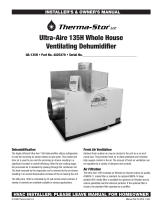
The Application Quick Start Guide is to be used as a reference only. Installation is to be performed by qualified heating and air conditioning professionals in accordance
with the Installation Manual provided with the dehumidifier.
Application
Single Zone Whole House or Basement N/A
Remote Control
(Single Zone)
Crawlspace, Sealed Attic,
Storage, Basement
N/A
MODEL 1830/1850/1870 DEHUMIDIFIER
APPLICATION QUICK START GUIDE
* Not recommended in
HVAC zoning appilcations
* Not recommended in
HVAC zoning appilcations

Application Sheet 1 – Single Zone Using Internal Control
Figure 3 Wiring (shown without “disable with
AC” feature being used)
Parts Needed (additional parts may be required):
__ Model 1830/1850/1870 __ Thermostat wire
__ Insulated duct __ 20A Outlet (1870 only)
__ Duct fittings & hardware
__ Grilles (if required)
__ Drain Pan and Float Switch (if required)
Figure 1 Dehumidifier Ducted to HVAC System
Figure 2 Dehumidifier Ducted Directly
Sequence of Operation
The dehumidifier will automatically “sample”
the air by turning on its blower (and the HVAC
blower if this option has been wired – see
Figure 3), and measuring the relative humidity
(RH) once every hour. Sampling will also occur
when the RH setting is lowered using the UP or
DOWN buttons on the control.
During sampling, if the RH of the air is above
the setting the dehumidifier, the compressor
will turn on. The compressor, dehumidifier
blower and HVAC system blower (if on) turns
off when the RH of the air is 3% RH below the
setting.
HVAC EQUIPMENT
RETURN
SUPPLY
HVAC EQUIPMENT
RETURN
SUPPLY
HVAC EQUIPMENT
RETURN
SUPPLY
Main Return to Main Supply
Main Return to Main Return - Recommended
Dedicated Return to Main Supply or Return
THERMOSTAT
OR
ZONE CONTROL BOARD

Application Sheet 2 – Single Zone Using External Control
Figure 3 Wiring (shown without “disable
with AC” feature being used)
Parts Needed (additional parts may be required):
__ Model 1830/1850/1870 __ Thermostat wire
__ Insulated duct __ 20A Outlet (1870 only)
__ Duct fittings & hardware __ Model 76, Model 8620
__ Grilles (if required) or Model 8910 control
__ Drain Pan and Float Switch (if required)
Figure 1 Dehumidifier Ducted to HVAC System
Figure 2 Dehumidifier Ducted Directly
External Control
The external control (i.e. Aprilaire Model 76
Dehumidifier Control, Model 8620
Thermostat or Model 8910 Home Comfort
Control) must have a normally open (NO –
all Aprilaire controls are normally open type)
or normally closed (NC) dry contact output,
and must be installed in the space that is
going to be dehumidified. Select the type of
control using the NO/NC dip switch on the
dehumidifier control.
Sequence of Operation
When the external control calls for
dehumidification, the dehumidifier blower
the HVAC blower (if this option has been
wired – see Figure 3) turn on, then three
seconds later the compressor turns on. All
will turn off when the external control stops
calling for dehumidification.
HVAC EQUIPMENT
RETURN
SUPPLY
HVAC EQUIPMENT
RETURN
SUPPLY
HVAC EQUIPMENT
RETURN
SUPPLY
Main Return to Main Supply
Main Return to Main Return - Recommended
Dedicated Return to Main Supply or Return
THERMOSTAT
OR
ZONE CONTROL BOARD

Application Sheet 3 – Remote Control Using Model 76 Control
Sequence of Operation
The Model 76 Dehumidifier Control can be installed in any convenient location within the living space while the
dehumidifier is installed in the space that is going to be dehumidified such as a crawl space, attic or basement. The
relative humidity (RH) displayed on the Model 76 is the RH in the space where the dehumidifier is located – the
dehumidifier communicates this to the Model 76. Changes to the dew point setting (1 – less dry, 7 – more dry) are
made at the Model 76 and communicated to the dehumidifier. The dehumidifier can be turned on and off using the
ON/OFF buttons of the Model 76.
Once every hour the dehumidifier will turn on its blower and sample the air in the zone to be dehumidified (sampling
will also occur whenever the dew point setting is raised). If the dew point of the air is higher than the setting on the
control, the dehumidifier compressor will turn on. When the dew point of the air is below the setting on the Model 76
Control, the dehumidifier will turn off.
When the Model 76 Control is wired to the dehumidifier in this application and after completing the set up (see Set Up
the Dehumidifier for Remote Control above), “REMOTE” will appear on the display of the dehumidifier control.
Parts Needed (additional parts may be required):
__ Model 1830/1850/1870
__ Model 76 Dehumidifier Control
__ Insulated duct
__ Thermostat wire
__ Duct fittings & hardware
__ 20A Outlet (1870 only)
__ Grilles (if required)
__ Drain pan and float switch (if required)
Figure 2 Wiring the Control
Figure 1 Dehumidifier Ducted Directly
A
B
C/-
R/+
DH
DH
MODEL 76 REMOTE
CONTROL
DH DH
HVAC EQUIP
Gh Rf Cf Gs W Y
FLOAT
SWITCH
NC
NO
DEHUMIDIFIER
CONTROL
BOARD
Set Up the Dehumidifier for Remote Control
After wiring the Model 76 to the dehumidifier as shown, use the
power switch located on the outlet panel of the dehumidifier to
power up the dehumidifier. The dehumidifier control should
display “OFF”.
1. Enter the Installer Set-Up menu by pressing and holding the
“Mode” button on the dehumidifier control for 3 seconds;
“REMOTE DISABLED” will appear on the display.
2. Press the Up or Down button to select “REMOTE ENABLED”.
3. Press the Mode button again to complete set up (“DONE”
will appear on the display).

ApplicationSheet4–TwoZoneusingInternalControl
PartsNeeded(additional
partsmayberequired):
__Model1830/1850/1870
__Insulatedduct
__Thermostatwire
__Ductfittings&hardware
__20AOutlet(1870only)
__Drainpanandfloatswitch(if
required)
__Grilles
__5442DamperKit(includes:
2–10”diaN.O.dampers,
2–10”diaN.C.dampersand
one40VA,24VACplug‐in
transformer)
Figure1Duct/DamperLayoutwith
WholeHouseasPrimar
y
Zone
Figure2Duct/DamperLayoutwith
BasementasPrimar
y
Zone
Figure3Wiring
SequenceofOperation
Adjusttherelativehumidity(RH)settingonthe
dehumidifiercontrol;thiswillbethesettingforboththe
PrimaryandSecondaryZone.Onceanhou r,the
dehumidifierwill“sample”theairinthePrimaryZone.
IfthereisnoneedfordehumidificationinthePrimary
Zonethedehumi di f i erwillthen sampletheairinthe
SecondaryZone.
WhensamplinginthePrimaryZonethedehumidifier
willenergizethedampersandthenturnonitsblower
(andtheHVACSystemblowerifwiredasshownin
Figure3),tomeasuretheRHoftheair.IftheRHofthe
airisabovethesetting,thecompressorwillturnon.If
thePrimaryZonedoesnotneeddehumidifica ti o n ,the
dampersarede‐energizedandtheHVACSystemBlower
(ifon)isturnedoffwhilethedehumidifierblower
continuestoruntosampletheairintheSecondary
Zone.IftheRHoftheairintheSecondaryZoneisabove
thesetting,thecompressorwillturnon.
SetUptheDehumidifierforZoning
1. With“OFF”showi ng onthecontrol,pressthe Modebuttonfor3secondstoentertheInstallerSetUpmenu
2. PresstheModebuttonuntil“ZONEDISABLED”appears.
3. PresstheUporDownbuttontochangeto“ZONEENABLED”.
4. PresstheModebuttonrepeatedlyuntil“DONE”showsonthedisplay.
G
HVAC
EQUIPMENT
THERMOSTAT
R
C
G
W
Y
EXISTING WIRE
NEW WIRE
ODT
SENSOR
DH DH
REMOTE
+ - AB
HVAC EQUIP
Gh Rf Cf Gs W Y
DAMPERS
VENT DEH
FLOAT
SWITCH
DEHUMIDIFIER
CONTROL BOARD
NC
NO
R
C
W
Y
N.C. DAMPERS
120
VAC
24
VAC
20 VA (MIN.)
TRANSFORMER
N.O. DAMPERS
HVAC EQUIPMENT
NORMALLY
CLOSED
DAMPER
NORMALLY
CLOSED
DAMPER
NORMALLY
OPEN DAMPER
NORMALLY
OPEN DAMPER
TO/FROM SECONDARY ZONE
TO BE DEHUMIDIFIED
TO/FROM PRIMARY ZONE TO BE
DEHUMIDIFIED
Note: Dehumidier zoning is not recommended in zoned HVAC applications.
ApplicationSheet4–TwoZoneusingInternalControl
PartsNeeded(additional
partsmayberequired):
__Model1830/1850/1870
__Insulatedduct
__Thermostatwire
__Ductfittings&hardware
__20AOutlet(1870only)
__Drainpanandfloatswitch(if
required)
__Grilles
__5442DamperKit(includes:
2–10”diaN.O.dampers,
2–10”diaN.C.dampersand
one40VA,24VACplug‐in
transformer)
Figure1Duct/DamperLayoutwith
WholeHouseasPrimar
y
Zone
Figure2Duct/DamperLayoutwith
BasementasPrimar
y
Zone
Figure3Wiring
SequenceofOperation
Adjusttherelativehumidity(RH)settingonthe
dehumidifiercontrol;thiswillbethesettingforboththe
PrimaryandSecondaryZone.Onceanhou r,the
dehumidifierwill“sample”theairinthePrimaryZone.
IfthereisnoneedfordehumidificationinthePrimary
Zonethedehumi di f i erwillthen sampletheairinthe
SecondaryZone.
WhensamplinginthePrimaryZonethedehumidifier
willenergizethedampersandthenturnonitsblower
(andtheHVACSystemblowerifwiredasshownin
Figure3),tomeasuretheRHoftheair.IftheRHofthe
airisabovethesetting,thecompressorwillturnon.If
thePrimaryZonedoesnotneeddehumidifica ti o n ,the
dampersarede‐energizedandtheHVACSystemBlower
(ifon)isturnedoffwhilethedehumidifierblower
continuestoruntosampletheairintheSecondary
Zone.IftheRHoftheairintheSecondaryZoneisabove
thesetting,thecompressorwillturnon.
SetUptheDehumidifierforZoning
1. With“OFF”showi ng onthecontrol,pressthe Modebuttonfor3secondstoentertheInstallerSetUpmenu
2. PresstheModebuttonuntil“ZONEDISABLED”appears.
3. PresstheUporDownbuttontochangeto“ZONEENABLED”.
4. PresstheModebuttonrepeatedlyuntil“DONE”showsonthedisplay.
G
HVAC
EQUIPMENT
THERMOSTAT
R
C
G
W
Y
EXISTING WIRE
NEW WIRE
ODT
SENSOR
DH DH
REMOTE
+ - AB
HVAC EQUIP
Gh Rf Cf Gs W Y
DAMPERS
VENT DEH
FLOAT
SWITCH
DEHUMIDIFIER
CONTROL BOARD
NC
NO
R
C
W
Y
N.C. DAMPERS
120
VAC
24
VAC
20 VA (MIN.)
TRANSFORMER
N.O. DAMPERS
HVAC EQUIPMENT
NORMALLY
CLOSED
DAMPER
NORMALLY
CLOSED
DAMPER
NORMALLY
OPEN DAMPER
NORMALLY
OPEN DAMPER
TO/FROM SECONDARY ZONE
TO BE DEHUMIDIFIED
TO/FROM PRIMARY ZONE TO BE
DEHUMIDIFIED

ApplicationSheet5–TwoZonewithExternalControlinPrimaryZone
PartsNeeded(additional
partsmayberequired):
__Model1830/1850/1870
__Model76,Model8620or
Model8910control
__Insulatedduct
__Thermostatwire
__Ductfittings&hardware
__20AOutlet(1870only)
__Drainpanandfloatswitch(if
required)
__Grilles
__5442DamperKit(includes:
2–10”diaN.O.dampers,
2–10”diaN.C.dampersand
one40VA,24VACplug‐in
transformer)
Figure1Duct/DamperLayoutwith
WholeHouseasPrimar
y
Zone
Figure2Duct/DamperLayoutwith
BasementasPrimar
y
Zone
Figure3Wiring
SequenceofOperation
Theexternalcontrol(i.e.Model76ControlorModel8910
HomeComfortControl)provideson‐demandcontrolofthe
dehumidifierforthePrimaryZone.WhenthePrimaryZone
callsfordehumidification,the dehumidifier energizesthe
dampers,andturnsonitsblowerandcompressor.The
dehumidifierwillalsoturnontheHVACSystemBlowerifwired
asshowninFigure3).ThePrimaryZonedemandwilloverride
anexistingSecondaryZonedemand.
TheSecondaryZoneiscontrolledbytherelativehumidity(RH)
settingatthedehumidifiercontrol.Onceanhour,or
immediatelyafterdehumidifyingtheprimaryzone,the
dehumidifierwill“sample”theairintheSecondaryZone.
Whensampling,thedampersarenotenergizedwhilethe
dehumidifierblowerrunsandtheRHismeasuredIftheRHis
abovethesettingonthecontrol,thecompressorwillturnon
andtheSecondaryZonewillbe dehumidified.
ODT
SENSOR
REMOTE
+ - AB
DAMPERS
VENT DEH
SetUptheDehumidifierforZoningandExternalControl
1. PresstheModebuttonfor3secondstoentertheInstallerSetUpmenu
2. PresstheModebuttonuntil“ZONEDISABLED”appears.
3. PresstheUporDownbuttontochangeto“ZONEENABLED”.
4. PresstheModebuttonagaintoshow“EXTERNALDISABLED”
5. PresstheUporDownbuttontochange to“EXTERNALENABLED”
6. PresstheModebuttonrepeatedlyuntil“DONE”showsonthedisplay.
HVAC EQUIPMENT
NORMALLY
CLOSED
DAMPER
NORMALLY
CLOSED
DAMPER
NORMALLY
OPEN DAMPER
NORMALLY
OPEN DAMPER
TO/FROM SECONDARY ZONE
TO BE DEHUMIDIFIED
TO/FROM PRIMARY ZONE TO BE
DEHUMIDIFIED
Note: Dehumidier zoning is not recommended in zoned HVAC applications.
ApplicationSheet5–TwoZonewithExternalControlinPrimaryZone
PartsNeeded(additional
partsmayberequired):
__Model1830/1850/1870
__Model76,Model8620or
Model8910control
__Insulatedduct
__Thermostatwire
__Ductfittings&hardware
__20AOutlet(1870only)
__Drainpanandfloatswitch(if
required)
__Grilles
__5442DamperKit(includes:
2–10”diaN.O.dampers,
2–10”diaN.C.dampersand
one40VA,24VACplug‐in
transformer)
Figure1Duct/DamperLayoutwith
WholeHouseasPrimar
y
Zone
Figure2Duct/DamperLayoutwith
BasementasPrimar
y
Zone
Figure3Wiring
SequenceofOperation
Theexternalcontrol(i.e.Model76ControlorModel8910
HomeComfortControl)provideson‐demandcontrolofthe
dehumidifierforthePrimaryZone.WhenthePrimaryZone
callsfordehumidification,the dehumidifier energizesthe
dampers,andturnsonitsblowerandcompressor.The
dehumidifierwillalsoturnontheHVACSystemBlowerifwired
asshowninFigure3).ThePrimaryZonedemandwilloverride
anexistingSecondaryZonedemand.
TheSecondaryZoneiscontrolledbytherelativehumidity(RH)
settingatthedehumidifiercontrol.Onceanhour,or
immediatelyafterdehumidifyingtheprimaryzone,the
dehumidifierwill“sample”theairintheSecondaryZone.
Whensampling,thedampersarenotenergizedwhilethe
dehumidifierblowerrunsandtheRHismeasuredIftheRHis
abovethesettingonthecontrol,thecompressorwillturnon
andtheSecondaryZonewillbe dehumidified.
ODT
SENSOR
REMOTE
+ - AB
DAMPERS
VENT DEH
SetUptheDehumidifierforZoningandExternalControl
1. PresstheModebuttonfor3secondstoentertheInstallerSetUpmenu
2. PresstheModebuttonuntil“ZONEDISABLED”appears.
3. PresstheUporDownbuttontochangeto“ZONEENABLED”.
4. PresstheModebuttonagaintoshow“EXTERNALDISABLED”
5. PresstheUporDownbuttontochange to“EXTERNALENABLED”
6. PresstheModebuttonrepeatedlyuntil“DONE”showsonthedisplay.
HVAC EQUIPMENT
NORMALLY
CLOSED
DAMPER
NORMALLY
CLOSED
DAMPER
NORMALLY
OPEN DAMPER
NORMALLY
OPEN DAMPER
TO/FROM SECONDARY ZONE
TO BE DEHUMIDIFIED
TO/FROM PRIMARY ZONE TO BE
DEHUMIDIFIED

Application Sheet 6 – Using the Ventilation Feature of the Dehumidifier
Parts needed for ventilation:
__ Model 6506 damper
__ Model 8052 Outdoor
Temperature Sensor
(optional)
__ Model 4010 10VA
Transformer
__ 6” Insulated Duct, fittings
and hardware
__ Intake Hood
__ Thermostat wire
Install
a
ventilation
duct
with a normally closed Model 6506 damper
to the return duct of the HVAC system
(see
Figure
1) and wire the dehumidifier to the HVAC system as shown in Figure 2. The outdoor temperature (ODT) sensor is used
to limit ventilation if the outdoor temperature gets too hot or too cold (see Set Up the Dehumidifier for Ventilation
below), if temperature limits are not needed, the ODT sensor does not have to be installed. Follow the set up
instructions below and set the number of minutes per hour that ventilation will be needed (refer to the Installation
Manual for details on determining how much ventilation is needed). Whenever the heating or cooling turns on, or
when the dehumidifier turns on, the dehumidifier will open the damper and bring in fresh outdoor air. If the
equipment doesn’t run for the set number of minutes, the dehumidifier will turn on HVAC fan at the end of the hour to
ensure ventilation needs are met.
Figure 1
Ventilation
Duct Location
Figure
2
Ventilation
Wiring
Using the Dehumidifier to Pre-Condition the Ventilation Air
The dehumidifier
can be used to
remove
moisture from the ventilation air before it is
delivered to the home. Install the ventilation
duct to the dehumidifier inlet duct as shown in
Figure 3. The control on the dehumidifier must
be used for the Primary Zone (i.e. an external
control cannot be used) in this installation. If
the RH of the incoming air is above the setting
on the control the air will be dehumidified.
Figure
3
Dehumidify
Ventilation Air
Set Up the Dehumidifier for Ventilation
1. With “OFF” showing on the control, press the Mode button for 3 seconds to enter the Installer Set Up menu
2. Press the Mode button until “VENT DISABLED” appears.
3. Press the Up or Down button to change to “VENT ENABLED”.
4. Press the Mode button and “VENT TIMED” will be displayed. Press the Up or Down button to toggle between:
TIMED: no temperature limits
AUTO – B: Ventilation not allowed if ODT > 100°F or ODT < 0°F; allowed only when heating if 0°F < ODT < 20°.
AUTO – C: Ventilation not allowed if ODT > 100°F or ODT < 0°F
AUTO – D: Ventilation not allowed if ODT > 90°F; allowed only when heating if 0°F < ODT < 40°F
5. Press the Mode button, the use the Up and Down buttons to set the Vent Time (minutes/hour).
6. Press Mode repeatedly until “DONE” appears on the display.
ODT
SENSOR
MODEL 6506
NORMALLY
CLOSED DAMPER
THERMOSTAT
OR
ZONE CONTROL
BOARD

P.O. Box 1467 • Madison, WI 53701
-
1467 • Phone: 800/334
-
6011 • Fax: 608/257
-
4357 •
www.aprilairepartners.com
10010431
Printed in U.S.A
B2206146�� © 2013 Aprilaire –
A division of Research Products Corp.
B
B2206146C
2016 Aprilaire – Division of Research Products Corp.
/