Samsung AM009JNGDCH/AA Installation guide
- Category
- Split-system air conditioners
- Type
- Installation guide
This manual is also suitable for

DVM Floor Stand_CS6_IM_05451A-00_EN.indd 1 2015-05-13 오전 10:45:31

Floor Standing Unit
AM✴✴✴JNFDCH✴
AM✴✴✴JNGDCH✴
Air Conditioner
installation manual
This manual is made with 100% recycled paper.
EN ES FR
imagine the possibilities
Thank you for purchasing this Samsung product.
DB68-05451A-00
DVM Floor Stand_CS6_IM_05451A-00_EN.indd 2 2015-05-13 오전 10:45:31

2
Contents
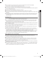
Safety Precautions
(Carefully follow the precautions listed below because they are essential to guarantee the safety of the equipment.)
WARNING
• Always disconnect the air conditioner from the power supply before servicing it or
accessing its internal components.
• Verify that installation and testing operations are performed by qualified personnel.
• Verify that the air conditioner is not installed in an easily accessible area.
General information
X Carefully read the content of this manual before installing the air conditioner and store the manual in a safe place in
order to be able to use it as reference after installation.
X For maximum safety, installers should always carefully read the following warnings.
X Store the operation and installation manual in a safe location and remember to hand it over to the new owner if the
air conditioner is sold or transferred.
X This manual explains how to install an indoor unit with a split system with two SAMSUNG units. The use of other
types of units with different control systems may damage the units and invalidate the warranty. The manufacturer
shall not be responsible for damages arising from the use of non compliant units.
X The manufacturer shall not be responsible for damage originating from unauthorized changes or the improper
connection of electric and hydraulic lines. Failure to comply with these instructions or to comply with the
requirements set forth in the “Operating limits” table, included in the manual, shall immediately invalidate the
warranty.
X The air conditioner should be used only for the applications for which it has been designed: the indoor unit is not
suitable to be installed in areas used for laundry.
X Do not use the units if damaged. If problems occur, switch the unit off and disconnect it from the power supply.
X I
n order to prevent electric shocks, fires or injuries, always stop the unit, disable the protection switch and contact
SAMSUNG’s technical support if the unit produces smoke, if the power cable is hot or damaged or if the unit is very noisy.
Safety Precautions . . . . . . . . . . . . . . . . . . . . . . . . . . . . . . . . . . . . . . . . . . . . . . . . . . . . . . . . . . . . . . . . . . . . . . . . . . . . . . . . . . . . . . . . . . . . . . 2
Accessories . . . . . . . . . . . . . . . . . . . . . . . . . . . . . . . . . . . . . . . . . . . . . . . . . . . . . . . . . . . . . . . . . . . . . . . . . . . . . . . . . . . . . . . . . . . . . . . . . . . . . 4
Selecting the installation location . . . . . . . . . . . . . . . . . . . . . . . . . . . . . . . . . . . . . . . . . . . . . . . . . . . . . . . . . . . . . . . . . . . . . . . . . . . . . . . . 5
Indoor unit installation . . . . . . . . . . . . . . . . . . . . . . . . . . . . . . . . . . . . . . . . . . . . . . . . . . . . . . . . . . . . . . . . . . . . . . . . . . . . . . . . . . . . . . . . . . 9
Purging the unit . . . . . . . . . . . . . . . . . . . . . . . . . . . . . . . . . . . . . . . . . . . . . . . . . . . . . . . . . . . . . . . . . . . . . . . . . . . . . . . . . . . . . . . . . . . . . . . . 9
Connecting the refrigerant pipe. . . . . . . . . . . . . . . . . . . . . . . . . . . . . . . . . . . . . . . . . . . . . . . . . . . . . . . . . . . . . . . . . . . . . . . . . . . . . . . . .10
Cutting/Flaring the pipes . . . . . . . . . . . . . . . . . . . . . . . . . . . . . . . . . . . . . . . . . . . . . . . . . . . . . . . . . . . . . . . . . . . . . . . . . . . . . . . . . . . . . . . 11
Performing leak test & insulation. . . . . . . . . . . . . . . . . . . . . . . . . . . . . . . . . . . . . . . . . . . . . . . . . . . . . . . . . . . . . . . . . . . . . . . . . . . . . . . . 13
Drain pipe and drain hose installation . . . . . . . . . . . . . . . . . . . . . . . . . . . . . . . . . . . . . . . . . . . . . . . . . . . . . . . . . . . . . . . . . . . . . . . . . . . 16
Water leakage test . . . . . . . . . . . . . . . . . . . . . . . . . . . . . . . . . . . . . . . . . . . . . . . . . . . . . . . . . . . . . . . . . . . . . . . . . . . . . . . . . . . . . . . . . . . . . 17
Pipe insulation. . . . . . . . . . . . . . . . . . . . . . . . . . . . . . . . . . . . . . . . . . . . . . . . . . . . . . . . . . . . . . . . . . . . . . . . . . . . . . . . . . . . . . . . . . . . . . . . .17
Wiring Work . . . . . . . . . . . . . . . . . . . . . . . . . . . . . . . . . . . . . . . . . . . . . . . . . . . . . . . . . . . . . . . . . . . . . . . . . . . . . . . . . . . . . . . . . . . . . . . . . . . 18
Setting an indoor unit address and installation option. . . . . . . . . . . . . . . . . . . . . . . . . . . . . . . . . . . . . . . . . . . . . . . . . . . . . . . . . . . .23
Final Checks and User Tips . . . . . . . . . . . . . . . . . . . . . . . . . . . . . . . . . . . . . . . . . . . . . . . . . . . . . . . . . . . . . . . . . . . . . . . . . . . . . . . . . . . . . . 34
Providing information for user . . . . . . . . . . . . . . . . . . . . . . . . . . . . . . . . . . . . . . . . . . . . . . . . . . . . . . . . . . . . . . . . . . . . . . . . . . . . . . . . . .34
DVM Floor Stand_CS6_IM_05451A-00_EN.indd 2 2015-05-13 오전 10:45:31

3
ENGLISH
X Always remember to inspect the unit, electric connections, refrigerant tubes and protections regularly.
These operations should be performed by qualified personnel only.
X The unit contains moving parts, which should always be kept out of the reach of children.
X Do not attempt to repair, move, alter or reinstall the unit. If performed by unauthorized personnel, these operations
may cause electric shocks or fires.
X Do not place containers with liquids or other objects on the unit.
X All the materials used for the manufacture and packaging of the air conditioner are recyclable.
X The packing material and exhaust batteries of the remote control(optional) must be disposed of in accordance with
current laws.
X The air conditioner contains a refrigerant that has to be disposed of as special waste. At the end of its life cycle, the
air conditioner must be disposed of in authorized centers or returned to the retailer so that it can be disposed of
correctly and safely.
Installing the unit
IMPORTANT: When installing the unit, always remember to connect first the refrigerant tubes, then the electrical lines.
Always disassemble the electric lines before the refrigerant tubes.
X Upon receipt, inspect the product to verify that it has not been damaged during transport. If the product appears
damaged, DO NOT INSTALL it and immediately report the damage to the carrier or retailer (if the installer or the
authorized technician has collected the material from the retailer.)
X After completing the installation, always carry out a functional test and provide the instructions on how to operate
the air conditioner to the user.
X Do not use the air conditioner in environments with hazardous substances or close to equipment that release free
flames to avoid the occurrence of fires, explosions or injuries.
X The air conditioner should be used only for the applications for which it has been designed: the indoor unit is not
suitable to be installed in areas used for laundry.
X Our units must be installed in compliance with the spaces indicated in the installation manual to ensure either
accessibility from both sides or ability to perform routine maintenance and repairs. The units’ components must be
accessible and that can be disassembled in conditions of complete safety either for people or things.
For this reason, where it is not observed as indicated into the Installation Manual, the cost necessary to reach and
repair the unit (in safety, as required by current regulations in force) with slings, trucks, scaffolding or any other
means of elevation won’t be considered in-warranty and charged to end user.
Power supply line, fuse or circuit breaker
X Always make sure that the power supply is compliant with current safety standards. Always install the air
conditioner in compliance with current local safety standards.
X Always verify that a suitable grounding connection is available.
X Verify that the voltage and frequency of the power supply comply with the specifications and that the installed
power is sufficient to ensure the operation of any other domestic appliance connected to the same electric lines.
X Always verify that the cut-off and protection switches are suitably dimensioned.
X Verify that the air conditioner is connected to the power supply in accordance with the instructions provided in the
wiring diagram included in the manual.
X Always verify that electric connections (cable entry, section of leads, protections…) are compliant with the electric
specifications and with the instructions provided in the wiring scheme. Always verify that all connections comply
with the standards applicable to the installation of air conditioners.
DVM Floor Stand_CS6_IM_05451A-00_EN.indd 3 2015-05-13 오전 10:45:31

4
Safety Precautions
• Make sure that you earth the cables.
- Do not connect the earth wire to the gas pipe, water pipe, lighting rod or telephone wire.
If earthing is not complete, electric shock or fire may occur.
• Install the circuit breaker.
- If the circuit breaker is not installed, electric shock or fire may occur.
• Make sure that the condensed water dripping from the drain hose runs out properly and safely.
• Install the power cable and communication cable of the indoor and outdoor unit at least 1m away from
the electric appliance.
• Install the indoor unit away from lighting apparatus using the ballast.
- If you use the wireless remote control, reception error may occur due to the ballast of the lighting
apparatus.
• Do not install the air conditioner in following places.
- Place where there is mineral oil or arsenic acid.
Resin parts flame and the accessories may drop or water may leak.
The capacity of the heat exchanger may reduce or the air conditioner may be out of order.
- The place where corrosive gas such as sulfurous acid gas generates from the vent pipe or air outlet.
The copper pipe or connection pipe may corrode and refrigerant may leak.
- The place where there is a machine that generates electromagnetic waves.
The air conditioner may not operate normally due to control system.
- The place where there is a danger of existing combustible gas, carbon fiber or flammable dust.
The place where thinner or gasoline is handled. Gas may leak and it may cause fire.
CAUTION
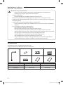
Accessories
The following accessories are supplied with the indoor unit.
The type and quantity may differ depending on the specifications.
Extension pipe Pipe insulator Drain insulator cover Insulator
Insulation cover band User's manual Installation manual
Extension pipe type Liquid pipe Gas pipe
✴✴006/009/012/018✴✴ Φ 6.35 (1/4”) Φ 12.7 (1/2”)
✴✴024✴✴ Φ 9.52 (3/8”) Φ 15.88 (5/8”)
DVM Floor Stand_CS6_IM_05451A-00_EN.indd 4 2015-05-13 오전 10:45:32

5
ENGLISH
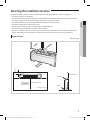
Selecting the installation location
Decide the installation location, with the consideration of the following conditions, under user’s approval.
• Place where air flow is not disturbed.
• Place with flat surface and where structure can bear the weight and vibration of the indoor unit. (If the structure is
not strong enough, indoor unit may fall and get damaged or cause personal injury.)
• Place where sufficient space can be guaranteed for maintenance and other services.
• Place where condensation can be drained easily.
• Place that allows refrigerant pipe connection within allowable distance.
• Place where indoor unit will not be exposed to direct sunlight.
• Place that can keep the distance of at least 3.28 ft (1 m) between power/communication cable and any electronic
devices. (Depending on the circumstances, problem may occur even if you secure 3.28 ft (1 m) of distance.)
Exposed Type
Unit: inch (mm)
6.89(175) or more
Air inlet
Air outlet
3.94(100) or more 3.94(100) or more
5.91(150) or more
0.79(20) or more
Front
39.37(1000) or more
DVM Floor Stand_CS6_IM_05451A-00_EN.indd 5 2015-05-13 오전 10:45:32

6
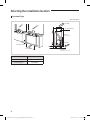
Selecting the installation location
Concealed Type
Unit: inch (mm)
Air inlet
Air outlet
Air filter
2.36 (60)
1.97 (50) or below
Cover
2.36 (60) or more
‘A’ or more
Model A
✴✴006/009/012✴✴ 27.56 (700)
✴✴018/024✴✴ 38.58 (980)
DVM Floor Stand_CS6_IM_05451A-00_EN.indd 6 2015-05-13 오전 10:45:32

7
ENGLISH
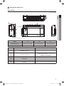
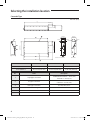
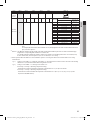
Drawing of the indoor unit
Exposed Type
Unit : inch (mm)
2
1
3
6
5
4
AA
C
B
9.23(234.5)9.23(234.5)
For fixing the product
8.62(219)
4.02(102.1)
15.81(401.5)
12.6(320)
2.81(71.5)
13.94(354)
4.6(116.9)
8.64(219.5)
0.71(18)0.71(18)
1.34(34)
1.34(34)
4 - Φ 0.39(10)
Hole to fix the product on floor
5.43(138)
0.71(18)
8.64(219.5)
2-Φ0.59(15)
8.66(220)
4.49(114)1.57(40)
5.77(146.6)
2.89(73.4)
23.62(600)
7.76(197)
10.81(274.5)
13.54(344)
Model "A" "B" "C"
✴✴006/009/012✴✴ 46.02 inch (1169mm) 28.74 inch (730 mm) 27.56 inch (700 mm)
✴✴018/024✴✴ 57.05 inch (1449mm) 39.76 inch (1010 mm) 38.58 inch (980 mm)
No. Name Description
1 Liquid pipe connection
✴✴006/009/012/018✴✴ : ø6.35 (1/4”)
✴✴024✴✴ : ø9.52 (3/8”)
2 Gas pipe connection
✴✴006/009/012/018✴✴ : ø12.7 (1/2”)
✴✴024✴✴ : ø15.88 (5/8”)
3 Drain pipe connection ID ø 18 (0.709”) Hose
4 Power wiring -
5 Air outlet -
6 Air intake -
DVM Floor Stand_CS6_IM_05451A-00_EN.indd 7 2015-05-13 오전 10:45:32

8
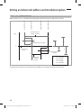
Selecting the installation location
Concealed Type
Unit: inch (mm)
6.5 (165)
2.76 (70)
8.66 (220)
6.12 (155.5)
18.72 (475.5)
22.83 (580)
8.66(220)
8.66(220)
3.94(100)
5.51(140)
3.15(80)
1.57(40)
1.57(40)
1.57(40)
AM009/012/018/024JNF✴ AM006JNF✴
8.66 (220)
Model "A" "B" "C"
✴✴006/009/012✴✴ 37.2 inch (945 mm) 28.74 inch (730 mm) 27.56 inch (700 mm)
✴✴018/024✴✴ 48.23 inch (1225 mm) 39.76 inch (1010 mm) 38.58 inch (980 mm)
No. Name Description
1 Liquid pipe connection
✴✴006/009/012/018✴✴ : ø6.35 (1/4”)
✴✴024✴✴ : ø9.52 (3/8”)
2 Gas pipe connection
✴✴006/009/012/018✴✴ : ø12.7 (1/2”)
✴✴024✴✴ : ø15.88 (5/8”)
3 Drain pipe connection ID ø 18 (0.709”) Hose
4 Power wiring -
5 Air outlet -
6 Air intake -
DVM Floor Stand_CS6_IM_05451A-00_EN.indd 8 2015-05-13 오전 10:45:33

9
ENGLISH
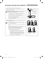
Indoor unit installation
Refrigerant pipe work must be done before installing the indoor unit.
1. Check the product and the location where it will be installed.
2. Check the required installation conditions.
3. Drill a hole on a floor or a wall and insert bolt anchors as shown in the
figure.
- Use a ø 9.52 (3/8”) or M10 bolts for installation.
- At least 2 anchor bolts must be used for fixing the indoor unit.
• All the part must be purchased separately.
• Service space must be secured.
CAUTION
Concrete
Hole for anchor
or plug
Fixing bolt ø 9.52 (3/8”) or M10
4. Select a location with no obstacles in surrounding area while allowing easy pipe and electrical installation, and also
consider a place where it may not fall or get shaken by vibration or any other external force.
5. Drill a hole for the drain on the bottom or rear side of the indoor unit with a diameter between 2.36~2.56 inch
(60~65 mm).
6. Make sure that product is in level.
- Check the horizontality by using a level or a vinyl tube with water etc.
• If the indoor unit is not installed in level, drain water may get in to the indoor unit due to incorrect
measurement of water level.
CAUTION
7. Fix the indoor unit by connecting it to the anchor bolt.
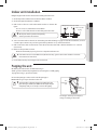
Purging the unit
On delivery, the indoor unit is loaded with inert gas.
All this gas must therefore be purged before connecting the assembly piping.
To purge the inert gas, proceed as follows.
Unscrew the pinch pipe at the end of each refrigerant pipe.
Result: All inert gas escapes from the indoor unit.
NOTE
• To prevent dirt or foreign objects from getting into the
pipes during installation, do NOT remove the pinch pipe
completely until you are ready to connect the piping.
The designs and shape are subject to
change according to the model.
Liquid
refrigerant
port
Gas
refrigerant
port
DVM Floor Stand_CS6_IM_05451A-00_EN.indd 9 2015-05-13 오전 10:45:33

10
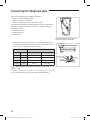
Connecting the refrigerant pipe
There are two refrigerant pipes of differing diameters:
• A smaller one for the liquid refrigerant
• A larger one for the gas refrigerant
• The inside of copper pipe must be clean & has no dust.
The connection procedure for the refrigerant pipes varies according to the
exit position of the pipes from the indoor unit, as seen when facing the
indoor in the “A” side.
• Liquid refrigerant port
• Gas refrigerant port
• Drain hose port
The designs and shape are subject to
change according to the model.
A
1. Remove the pinch pipe on the pipes and connect the assembly pipes
to each pipe, tightening the nuts, first manually and then with a torque
wrench, a spanner applying the following torque.
Outer Diameter Torque
mm inch N • m ibf • ft
6.35 1/4 14~18 10.3~13.3
9.52 3/8 34~42 25.1~31.0
12.70 1/2 49~61 36.1~45.0
15.88 5/8 68~82 50.2~60.5
NOTE
• Must apply refrigerant oil on the flaring area to prevent a
leak.
Refrigerant oil
Torque wrench
Flare nut
Union
Spanner
2. Be sure that there must be no crack or kink on the bended area.
DVM Floor Stand_CS6_IM_05451A-00_EN.indd 10 2015-05-13 오전 10:45:33

11
ENGLISH
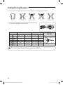
Cutting/Flaring the pipes
1. Make sure that you prepared the required tools. (pipe cutter, reamer, flaring tool and pipe holder)
2. If you want to shorten the pipe, cut it using a pipe cutter ensuring that
the cut edge remains at 90° with the side of the pipe. There are some
examples of correctly and incorrectly cut edges below.
90° Oblique Rough Burr
3. To prevent a gas leak, remove all burrs at the cut edge of the pipe using a reamer.
4. Carry out flaring work using flaring tool as shown below.
Flaring tool
Clutch type Wing nut type
A
Die
Copper pipe
Yoke
Die
Copper
pipe
Flare nut
Outer diameter (D)
Depth of aring part (A)
Using aring tool for
R-410A
Using conventional aring tool
Clutch type Wing nut type
mm inch mm inch mm inch mm inch
6.35 1/4 0~0.5 0~0.02 1.0~1.5 0.04~0.06 1.5~2.0 0.06~0.08
9.52 3/8 0~0.5 0~0.02 1.0~1.5 0.04~0.06 1.5~2.0 0.06~0.08
12.70 1/2 0~0.5 0~0.02 1.0~1.5 0.04~0.06 1.5~2.0 0.06~0.08
15.88 5/8 0~0.5 0~0.02 1.0~1.5 0.04~0.06 1.5~2.0 0.06~0.08
DVM Floor Stand_CS6_IM_05451A-00_EN.indd 11 2015-05-13 오전 10:45:34

12
Cutting/Flaring the pipes
5. Check if you flared the pipe correctly. There are some examples of incorrectly flared pipes below.
InclinedCorrect Damaged Surface Cracked Uneven Thickness
6. Align the pipes and tighten the flare nuts first manually and then with
a torque wrench, applying the following torque.
Outer diameter Connection Torque Flare dimension
Flare shape
[mm (inch)]
mm inch kgf•cm lbf • ft mm inch
6.35 1/4 14~18 10.3~13.3 8.7~9.1 0.34~0.36
R 0.4~0.8
(0.016~0.032)
90° ±2°
45° ±2°
9.52 3/8 34~42 25.1~31.0 12.8~13.2 0.50~0.52
12.70 1/2 49~61 36.1~45.0 16.2~16.6 0.64~0.65
15.88 5/8 68~82 50.2~60.5 19.3~19.7 0.76~0.78
19.05 3/4 100~120 73.8~88.5 23.6~24.0 0.93~0.94
• In case of needing brazing, you must work with Nitrogen gas blowing.
CAUTION
DVM Floor Stand_CS6_IM_05451A-00_EN.indd 12 2015-05-13 오전 10:45:34

13
ENGLISH
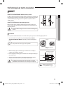
Performing leak test & insulation
Leak test
LEAK TEST WITH NITROGEN (before opening valves)
In order to detect basic refrigerant leaks, before recreating the vacuum and
recirculating the R-410A, it’s responsible of installer to pressurize the whole
system with nitrogen (using a pressure regulator) at a pressure above
4.1MPa (gauge).
LEAK TEST WITH R-410A (after opening valves)
Before opening valves, discharge all the nitrogen into the system and
create vacuum. After opening valves check leaks using a leak detector for
refrigerant R-410A.
• Discharge all the nitrogen to create a vacuum and charge the
system.
CAUTION
Check for leakage
Insulation
Once you have checked that there are no leaks in the system, you can insulate the piping and hose.
1. To avoid condensation problems, place T13.0 (0.51”) or thicker
Acrylonitrile Butadien Rubber separately around each refrigerant
pipe.
NOTE
• Always make the seam of pipes face upwards.
No gap
NBR [T13.0 (0.51”) or
thicker]
2. Wind insulating tape around the pipes and drain hose avoiding to
compress the insulation too much.
Insulation cover pipe
Indoor unit
Be sure to overlap
the insulation
Insulation pipe
• Must fit tightly against
body without any gap.
CAUTION
3. Finish wrapping insulating tape around the rest of the pipes leading to
the outdoor unit.
4. The pipes and electrical cables connecting the indoor unit with the
outdoor unit must be fixed to the wall with suitable ducts.
• All refrigerant connection must be accessible, in order to
permit either unit maintenance or removing it completely.
CAUTION
DVM Floor Stand_CS6_IM_05451A-00_EN.indd 13 2015-05-13 오전 10:45:35

14
Performing leak test & insulation
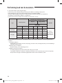
5. Select the insulation of the refrigerant pipe.
• Insulate the gas side and liquid side pipe referring to the thickness according to the pipe size.
• Indoor temperature of 86 °F(30 °C) and humidity of 85% is the standard condition.
If install in a high humidity condition,use one grade thicker insulator by referring to the table below.
If installing in an unfavorable conditions, use thicker one.
• Insulator’s heat-resistance temperature should be more than 248 °F (120 °C).
Pipe
Outer diameter
Insulation Type (Cooling/Heating)
Remarks
General
[30 °C (86 °F), 85 %]
High humidity
[30 °C (86 °F), 85 %]
EPDM, NBR
mm inch mm inch mm inch
Liquid pipe
6.35~9.52 1/4~3/8 9 3/8 9 3/8
Internal
temperature
is higher than
248 °F (120 °C)
12.7~50.8 1/2~2 13 1/2 13 1/2
Gas pipe
6.35 1/4 13 1/2 19 3/4
9.52~25.4 3/8~1 19 3/4 25 1
28.58~44.45 1 1/8~1 3/4 19 3/4 32 1 1/4
50.8 2 25 1 38 1 1/2
• When installing insulation in places and conditions below, use the same insulation that is used for high humidity
conditions.
<Geological condition>
- High humidity places such as shoreline, hot spring, near lake or river, and ridge (when the part of the building is
covered by earth and sand.)
<Operation purpose condition>
- Restaurant ceiling, sauna, swimming pool etc.
<Building construction condition>
- The ceiling frequently exposed to moisture and cooling is not covered.
e.g. The pipe installed at a corridor of a dormitory and studio or near an exit that opens and closes frequently.
- The place where the pipe is installed is highly humid due to the lack of ventilation system.
DVM Floor Stand_CS6_IM_05451A-00_EN.indd 14 2015-05-13 오전 10:45:35

15
ENGLISH
Refrigerant pipe before EEV kit and MCU or without EEV kit and MCU
• You can contact the gas side and liquid side pipes but the pipes should
not be pressed.
• When contacting the gas side and gas side pipe, use 1 grade thicker
insulator.
Gas pipe
Liquid pipe
Insulation
Insulation
Refrigerant pipe after EEV kit and MCU
• Install the gas side and liquid side pipes, leave 0.39 inch (10 mm) of
space.
• When contacting the gas side and liquid side pipe, use 1 grade thicker
insulator.
Gas pipe
0.39 inch (10 mm)0.39 inch (10 mm) 0.39 inch (10 mm)
Liquid pipe
• Install the insulation not to get wider and use the adhesives on the connection part of it to prevent
moisture from entering.
• Wind the refrigerant pipe with insulation tape if it is exposed to outside sunlight.
• Install the refrigerant pipe respecting that the insulation does not get thinner on the bent part or hanger
of pipe.
• Add the additional insulation if the insulation plate gets thinner.
Additional insulation
Hanger
Refrigerant pipe insulation
a×3
a
CAUTION
DVM Floor Stand_CS6_IM_05451A-00_EN.indd 15 2015-05-13 오전 10:45:35

16
Drain pipe and drain hose installation
1. Install a drain pipe according to following instruction.
2. When you complete the drain hose installation, pour water to make
sure water is drained properly.
• Make sure to keep the drain hose from getting tangled or
loosed (on the connection part).
• If it is necessary, connect a extension hose (drain hose) to
drain hose for indoor unit and insulate the external surface
of the extension hose if it is connected in indoor.
• If you installed a drain pipe underneath the refrigerant pipe,
make sure to fix the drain hose firmly.
• If you install the drain hose by drilling a hole on a wall, make
sure that slope is downward.
CAUTION
Drain pan
Internal water pipe
(within the product)
(Outer diameter ø 19 (3/4”))
External water pipe
(outside the product)
(Outer diameter ø 19 (3/4”))
50cm or more
3. When passing the drain hose through the hole drilled in the wall, make
sure to avoid following cases.
• Since the draining is of natural drain type, install the drain
hose in downward direction.
• If you do not tie the drain hose with a cable tie, leakage may
occur.
• Drain pipe may get clogged if there is any foreign substances
within the drain pan, so you must remove any foreign
substances after completing the installation.
• Do not use the drain hose (extension hoses) that is
connected by number of hoses together.
- Water may leak from the connection part, therefore
install the drain hose in one piece. However, if the
length is too short and you cannot avoid connecting
number of drain hoses together, make sure to use
silicone sealant or other material for water-proofing
measures. (Do not use insulating tape.)
CAUTION
Sewage
5cm or below
Distance between
the drain hose and
the ground is too
close
End of the
drain hose is
in a sewage
Drain hose is
slanted upward
End of the drain
hose is under
water
Drain hose
is bent
DVM Floor Stand_CS6_IM_05451A-00_EN.indd 16 2015-05-13 오전 10:45:36

17
ENGLISH
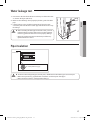
Water leakage test
1. Pour water to the hole for the drain test or drain pan of the indoor unit
as shown in the figure. (About 1ℓ)
2. Make sure that draining is done properly by checking end of the drain
pipe.
3. If water leakage occurs, check the horizontality of the indoor unit,
connection part of the drain hose/drain pipe and take measure to stop
the leakage.
• After connecting the drain pipe to the indoor unit, you must
perform leakage test. If the drain test has not done properly,
water may get into the indoor and cause property damage.
• Empty the condensation water in the drain pan before any
repair/maintenance service.
CAUTION
Pipe insulation
Indoor unit
Fix securely without any gap.
• You must insulate refrigerant pipes, branch joints, distribution header and the pipe connection part.
• Make sure to prevent any gap between the insulation on the bent part of the pipes.
• Make sure that insulation is overlapped when fixing it.
CAUTION
DVM Floor Stand_CS6_IM_05451A-00_EN.indd 17 2015-05-13 오전 10:45:36

18
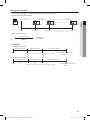
Wiring Work
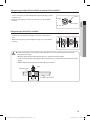
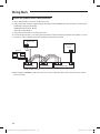
Power and communication cable connection
1. Before wiring work, you must turn off all power source.
2. Indoor unit power should be supplied through the breaker ( ELCB or MCCB+ELB ) separated by the outdoor power.
ELCB: Earth Leakage Circuit Breaker
MCCB: Molded Case Circuit Breaker
ELB: Earth Leakage Breaker
3. The power cable should be used only copper wires.
4. Connect the power cable (L1, L2) among the units within maximum length and communication cable(F1, F2) each.
5. Connect F3, F4(for communication) when installing the wired remote control.
L1 L2
L1 L2
ELCB
MCCB+
ELB
L1 L2
Indoor Unit 1
Outdoor Unit
Indoor Unit 2 Indoor Unit 3
Wired Remote
Control
208-230V~
❈ ELCB : Essential Installation
or
❈ When Installing ELCB(MCCB + ELB) indoor unit, do not connect with other indoor units attached to other outdoor
units(system A/C).
DVM Floor Stand_CS6_IM_05451A-00_EN.indd 18 2015-05-13 오전 10:45:36

19
ENGLISH
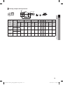
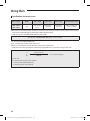
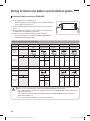
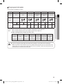
Selecting compressed ring terminal
Silver solder
Norminal
dimensions
for cable
(inch
2
)
Norminal
dimensions
for screw
(inch)
B D d1 E F L d2 t
Standard
dimension
(inch)
Allowance
(inch)
Standard
dimension
(inch)
Allowance
(inch)
Standard
dimension
(inch)
Allowance
(inch)
Min. Min. Max.
Standard
dimension
(inch)
Allowance
(inch)
Min.
0.0023
0.16 0.26
±0.0079 0.13
+0.012
-0.0079
0.067 ±0.0079 0.16 0.24 0.63 0.17
±0.0079
0
0.028
0.16 0.31
0.0039
0.16 0.26
±0.0079 0.17
+0.012
-0.0079
0.091 ±0.0079 0.24 0.24 0.69 0.17
±0.0079
0
0.031
0.16 0.33
0.0062 0.16 0.37 ±0.0079 0.22
+0.012
-0.0079
0.134 ±0.0079 0.24 0.20 0.79 0.17
±0.0079
0
0.035
DVM Floor Stand_CS6_IM_05451A-00_EN.indd 19 2015-05-13 오전 10:45:36
Page is loading ...
Page is loading ...
Page is loading ...
Page is loading ...
Page is loading ...
Page is loading ...
Page is loading ...
Page is loading ...
Page is loading ...
Page is loading ...
Page is loading ...
Page is loading ...
Page is loading ...
Page is loading ...
Page is loading ...
Page is loading ...
-
 1
1
-
 2
2
-
 3
3
-
 4
4
-
 5
5
-
 6
6
-
 7
7
-
 8
8
-
 9
9
-
 10
10
-
 11
11
-
 12
12
-
 13
13
-
 14
14
-
 15
15
-
 16
16
-
 17
17
-
 18
18
-
 19
19
-
 20
20
-
 21
21
-
 22
22
-
 23
23
-
 24
24
-
 25
25
-
 26
26
-
 27
27
-
 28
28
-
 29
29
-
 30
30
-
 31
31
-
 32
32
-
 33
33
-
 34
34
-
 35
35
-
 36
36


Samsung AM009JNGDCH/AA Installation guide
- Category
- Split-system air conditioners
- Type
- Installation guide
- This manual is also suitable for
Ask a question and I''ll find the answer in the document
Finding information in a document is now easier with AI
Related papers
-
Samsung AM140RNPDKH/EU User manual
-
-
Samsung AM112HNMPKH/TK User manual
-
Samsung MWR-SH00 Installation guide
-
-
-
-
Samsung AM036FNFDEH/EU Installation guide
-
-
Other documents
-
DREO DR-HSH001 User guide
-
Carrier 42VMC User manual
-
LG PHLTA Installation guide
-
-
LG LAN091CNP, LAU091CNP, LAN121CNP User manual
-
-
-
Airwell PNV 007 Installation guide
-
Rubine RWH-IA9100DC-RGB User manual
-
 FPPI 07-003-00 Installation guide
