FreeMotion EPIC SHOULDER F807.0 Owner's manual
- Type
- Owner's manual
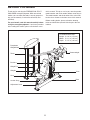
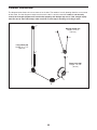
FreeMotion EPIC SHOULDER F807.0 is a strength equipment that can be used to work out your body's muscle groups effectively and efficiently, with unrestricted motion. It is suitable for both home and commercial use, and can support a maximum user weight of 350 lbs. (159 kg). The device comes with various features that enhance your workout experience, such as a drop-down weight, a counterweight tower, an adjustable seat, and an anchor strap for stability. With proper use and maintenance, the FreeMotion EPIC SHOULDER F807.
FreeMotion EPIC SHOULDER F807.0 is a strength equipment that can be used to work out your body's muscle groups effectively and efficiently, with unrestricted motion. It is suitable for both home and commercial use, and can support a maximum user weight of 350 lbs. (159 kg). The device comes with various features that enhance your workout experience, such as a drop-down weight, a counterweight tower, an adjustable seat, and an anchor strap for stability. With proper use and maintenance, the FreeMotion EPIC SHOULDER F807.


-
 1
1
-
 2
2
-
 3
3
-
 4
4
-
 5
5
-
 6
6
-
 7
7
-
 8
8
-
 9
9
-
 10
10
-
 11
11
-
 12
12
-
 13
13
-
 14
14
-
 15
15
-
 16
16
-
 17
17
-
 18
18
-
 19
19
-
 20
20
-
 21
21
-
 22
22
-
 23
23
-
 24
24
-
 25
25
-
 26
26
-
 27
27
-
 28
28


FreeMotion EPIC SHOULDER F807.0 Owner's manual
- Type
- Owner's manual
FreeMotion EPIC SHOULDER F807.0 is a strength equipment that can be used to work out your body's muscle groups effectively and efficiently, with unrestricted motion. It is suitable for both home and commercial use, and can support a maximum user weight of 350 lbs. (159 kg). The device comes with various features that enhance your workout experience, such as a drop-down weight, a counterweight tower, an adjustable seat, and an anchor strap for stability. With proper use and maintenance, the FreeMotion EPIC SHOULDER F807.
Ask a question and I''ll find the answer in the document
Finding information in a document is now easier with AI
Related papers
-
FreeMotion F812.0 Owner's manual
-
-
-
-
-
-
-
-
-
Other documents
-
 Flash Furniture BZ105BLK Operating instructions
-
Boss Office Products B9540-BK Operating instructions
-
-
GBC 387326E Datasheet
-
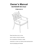 Firesense 62110 User manual
-
Weider WEEVSY1909 User manual
-
-
NordicTrack NTSY24918F.0 User manual
-
Gold's Gym XRS 50 User manual
-
Pro-Form Fusion 6.0 LX User manual

