Page is loading ...

Brake Wheels and Couplings
Technical Manual
Part Number: 560042 R0
March 2016
©Copyright 2016 Magnetek

Brake Wheels and Couplings Technical Manual
March 2016
Page 2 of 15
Table of Contents
Service Contact Information ...................................................................................................................... 3
Preface and Safety ...................................................................................................................................... 4
Product Safety Information ........................................................................................................................ 4
Product Warranty Information ................................................................................................................... 4
DANGER, WARNING, CAUTION, and NOTE Statements ....................................................................... 5
Wheels .......................................................................................................................................................... 6
Materials .................................................................................................................................................... 6
Angled Brake Wheel (ABW) ...................................................................................................................... 6
Applications ........................................................................................................................................... 6
Offset Brake Wheel (OBW) ....................................................................................................................... 7
Applications ........................................................................................................................................... 7
Coupling Brake Wheel (CBW) ................................................................................................................... 8
Applications ........................................................................................................................................... 8
Discs ............................................................................................................................................................. 9
Materials .................................................................................................................................................... 9
Applications ............................................................................................................................................... 9
Couplings ................................................................................................................................................... 10
Material .................................................................................................................................................... 10
Installation ................................................................................................................................................. 10
Product Inspection (Component Quantities) ........................................................................................... 10
CBW .................................................................................................................................................... 10
Instructions .............................................................................................................................................. 11
ABW and OBW .................................................................................................................................... 11
CBW .................................................................................................................................................... 13
Operational Tests ...................................................................................................................................... 14
Maintenance .............................................................................................................................................. 15
Inspection ................................................................................................................................................ 15
Replacement ........................................................................................................................................... 15
Storage ....................................................................................................................................................... 15

Brake Wheels and Couplings Technical Manual
March 2016
Page 3 of 15
Service Contact Information
For questions regarding service or technical information contact:
1-866-MAG-SERV
(1-866-624-7378)
Magnetek Material Handling
N49 W13650 Campbell Drive
Menomonee Falls, WI 53051
Telephone: 800-288-8178
Website: www.magnetek.com
E-mail: mhcustomerservice@magnetek.com
Fax Numbers:
Main: 800-298-3503
Sales: 262-783-3510
Service: 262-783-3508
Magnetek, Inc. has additional satellite locations for Canada and the United States. For more information,
please visit http://www.magnetek.com.

Brake Wheels and Couplings Technical Manual
March 2016
Page 4 of 15
Preface and Safety
©2016 MAGNETEK
All rights reserved. This notice applies to all copyrighted materials included with this product, including,
but not limited to, this manual. This manual is intended for the sole use of the persons to whom it was
provided, and any unauthorized distribution of the manual or dispersal of its contents is strictly forbidden.
This manual may not be reproduced in whole or in part by any means whatsoever without the expressed
written permission of Magnetek.
Product Safety Information
Magnetek, Inc. (Magnetek) offers a broad range of radio remote control products, control products and
adjustable frequency drives, industrial braking systems, and power delivery products for material handling
applications. This manual has been prepared by Magnetek to provide information and recommendations
for the installation, use, operation and service of Magnetek’s material handling products and systems
(Magnetek Products). Anyone who uses, operates, maintains, services, installs or owns Magnetek
Products should know, understand and follow the instructions and safety recommendations in this manual
for Magnetek Products.
The recommendations in this manual do not take precedence over any of the following requirements
relating to cranes, hoists, lifting devices or other equipment which use or include Magnetek
Products:
Instructions, manuals, and safety warnings of the manufacturers of the equipment where the
Magnetek Products are used,
Plant safety rules and procedures of the employers and the owners of the facilities where the
Magnetek Products are being used,
Regulations issued by the Occupational Health and Safety Administration (OSHA),
Applicable local, state, provincial, or federal codes, ordinances, standards and requirements, or
Safety standards and practices for the industries in which Magnetek Products are used.
This manual does not include or address the specific instructions and safety warnings of these
manufacturers or any of the other requirements listed above. It is the responsibility of the owners, users
and operators of the Magnetek Products to know, understand and follow all of these requirements. It is
the responsibility of the employer to make its employees aware of all of the above listed requirements and
to make certain that all operators are properly trained.
No one should use Magnetek Products prior to becoming familiar with and being trained in these
requirements and the instructions and safety recommendations for this manual.
Product Warranty Information
Magnetek, hereafter referred to as Company, assumes no responsibility for improper programming of a
device (such as a drive or radio) by untrained personnel. A device should only be programmed by a
trained technician who has read and understands the contents of the relevant manual(s). Improper
programming of a device can lead to unexpected, undesirable, or unsafe operation or performance of the
device. This may result in damage to equipment or personal injury. Company shall not be liable for
economic loss, property damage, or other consequential damages or physical injury sustained by the
purchaser or by any third party as a result of such programming. Company neither assumes nor
authorizes any other person to assume for Company any other liability in connection with the sale or use
of this product.
For information on Magnetek’s product warranties by product type, please visit www.magnetek.com.

Brake Wheels and Couplings Technical Manual
March 2016
Page 5 of 15
DANGER, WARNING, CAUTION, and NOTE Statements
Read and understand this manual before installing, operating, or servicing this product. Install the product
according to this manual and local codes.
The following conventions indicate safety messages in this manual. Failure to heed these messages
could cause fatal injury or damage products and related equipment and systems.
DANGER
DANGER indicates an imminently hazardous situation which, if not avoided, will result in death or serious
injury. This signal word is to be limited to the most extreme situations.
WARNING
WARNING indicates a potentially hazardous situation which, if not avoided, could result in death or
serious injury.
CAUTION
CAUTION indicates a potentially hazardous situation which, if not avoided, could result in minor or
moderate injury. It may also be used to alert against unsafe practices.
NOTE: A NOTE statement is used to notify people of installation, operation, programming, or
maintenance information that is important, but not hazard-related.

Brake Wheels and Couplings Technical Manual
March 2016
Page 6 of 15
Wheels
Materials
All Magnetek wheels are manufactured from 65-45-12 ductile iron, with a minimum tensile strength of 65
ksi, a minimum yield strength of 45 ksi, a Brinell hardness of 131-220, and 12% elongation.
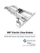
Angled Brake Wheel (ABW)
Applications
The ABW is a time-saving AIST-compliant drop-in wheel, best suited for the rugged environment of
overhead crane service in the steel industry.
Figure 1: Angled Brake Wheel (ABW) Dimensions
Table 1: ABW Dimensions
OD
(D)
OD
WIDTH
(C)
BORE (B) OFFSET (O)
HUB LENGTH
(E)
HUB
DIAMETER (S)
WEIGHT
(LBS)
WK
2
(LB-FT
2
)
MAX
RPM
HEAT
DISSIPATION
(FT.
LB/HOUR)
MIN MAX MIN MAX MIN MAX MAX
5 (1) 2.75 0.50 1.88 1.88 3.00 2.45 3.57 3.13 16 0.32 12,000 1,000,000
8 3.25 0.75 2.13 2.62 5.09 1.98 6.00 3.75 32 1.34 5,000 1,800,000
10 3.75 0.75 2.88 2.89 4.83 2.05 5.00 4.75 47 3.51 4,000 2,500,000
13 5.75 0.88 4.13 3.24 6.28 1.89 7.50 6.75 115 14.00 3,300 4,200,000
16 6.75 1.00 4.13 4.84 6.54 2.77 7.26 6.75 160 35.00 2,600 6,000,000
19 8.75 1.00 4.38 5.62 7.07 3.19 6.25 7.00 220 74.00 2,300 8,500,000
23 11.25 1.00 5.75 4.47 9.07 2.59 9.28 9.50 333 131.00 1,900 13,000,000
30 14.25 2.00 8.00 9.76 12.98 5.12 13.10 13.50 1,046 755.00 1,600 21,000,000
(1) NOT AISE - NEMA DOES NOT DEFINE A 5" BRAKE.
ALL DIMENSIONS ARE IN INCHES

Brake Wheels and Couplings Technical Manual
March 2016
Page 7 of 15
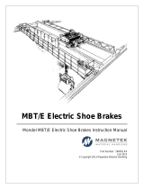
Offset Brake Wheel (OBW)
Applications
The OBW is a general all-purpose wheel, providing even heat distribution for all applications.
Figure 2: Offset Brake Wheel (OBW) Dimensions
Table 2: OBW Dimensions
OD(D)
OD
WIDTH
(C)
BORE (B) OFFSET(O)
HUB LENGTH
(E)
HUB
DIAMETER
(S)
WEIGHT
(LBS)
WK
2
(LB-
FT
2
)
MAX
RPM
HEAT
DISSIPATION
(FT. LB/HOUR)
MIN MAX MIN MAX MIN MAX MAX
4 2.25 0.38 1.88 1.38 2.63 3.63 4.88 3.00 10 0.12 10,000 810,000
6 3.25 0.50 1.88 0.62 3.40 1.10 5.03 3.06 16 0.46 9,000 1,400,000
8 4.25 0.75 2.63 0.63 4.44 1.26 6.57 4.25 41 1.95 8,000 2,000,000
10 4.25 0.75 2.63 0.69 4.63 1.38 6.76 4.50 59 4.44 6,000 2,600,000
12 5.25 0.75 3.13 0.89 5.63 1.78 8.63 5.13 84 8.85 5,000 3,600,000
13 5.75 0.75 3.63 0.83 5.50 1.66 8.38 5.85 114 14.00 4,500 4,100,000
15 6.75 1.00 5.00 1.00 6.25 2.00 9.63 8.00 196 30.00 4,000 5,400,000
16 6.75 1.00 5.00 1.13 6.72 2.26 10.10 8.00 219 39.00 3,500 5,800,000
19 8.75 2.00 5.63 1.50 8.38 3.00 13.25 9.00 370 96.00 3,000 8,400,000
23 11.25 2.00 6.25 1.63 10.00 3.26 15.63 10.00 584 223.00 2,500 12,000,000
30 14.25 2.50 8.38 1.63 11.60 3.26 18.73 13.50 1,176 731.00 2,000 21,000,000
ALL DIMENSIONS ARE IN INCHES

Brake Wheels and Couplings Technical Manual
March 2016
Page 8 of 15
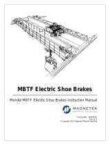
Coupling Brake Wheel (CBW)
Applications
The CBW is best suited for environments where space is limited. The CBW also eliminates the need for
double shaft extensions on motors and gearboxes.
Figure 3: Coupling Brake Wheel (CBW) Dimensions
Table 3: CBW Dimensions
OD
(D)
OD
WIDTH
(C)
BORE (B1) OFFSET(O)
HUB
DIAMETER
(HD)
HUB
WIDTH
(HW)
BORE (B2)
COUPLING
HUB DIA.
(CS)
GAP
MINIMUM
CLEARANCE
FOR
INSTALLATION
(M)
HUB
DIAMETER
(S)
WEIGHT
(LBS)
WK
2
(LB-
FT
2
)
MAX
RPM
MIN MAX MIN MAX MIN MAX MAX
6 3.25 0.50 1.88 0.62 3.40 2.31 1.69 0.44 1.625 3.06 0.16 1.66 3.00 19 0.51 9,000
8 4.25 0.75 2.63 0.63 4.44 3.00 1.94 0.69 2.125 3.97 0.16 1.88 4.11 39 1.66 8,000
10 4.25 0.75 2.63 0.69 4.63 3.00 1.94 0.69 2.125 3.97 0.16 1.88 4.11 49 3.43 6,000
12 5.25 0.75 3.13 0.89 5.63 4.00 2.44 0.94 2.75 4.86 0.16 2.38 4.84 86 7.04 5,000
13 5.75 0.75 3.63 0.83 5.50 4.00 2.44 0.94 2.75 4.86 0.16 2.38 4.96 92 12.02 4,500
15 6.75 1.00 5.00 1.00 6.25 4.63 3.03 1.44 3.25 5.84 0.19 2.88 6.10 150 25.96 4,000
16 6.75 1.00 5.00 1.13 6.72 5.63 3.59 1.44 4.00 6.84 0.19 3.31 6.99 194 35.70 3,500
19 8.75 2.00 5.63 1.50 8.38 6.50 4.19 1.81 4.625 7.91 0.22 3.81 8.16 327 86.43 3,000
23 11.25 2.00 6.25 1.63 10.00 7.50 4.75 2.44 5.375 9.25 0.31 4.25 9.66 549 22.97 2,500
30 14.25 2.50 8.38 1.63 11.60 9.50 6.03 3 6.50 11.56 0.34 5.50 11.98 1,028 683.34 2,000
ALL DIMENSIONS ARE IN INCHES

Brake Wheels and Couplings Technical Manual
March 2016
Page 9 of 15
Discs
Materials
All Magnetek discs are manufactured from 1020 AISI steel, with an ultimate tensile strength of 60.9 ksi, a
tensile strength yield of 50.8 ksi, a Brinell hardness of 121, and 15% elongation.
Applications
The discs are best suited for hard-wear surfaces, providing longer friction pad life and simple friction pad
changes.
Figure 4: Disc Dimensions

Brake Wheels and Couplings Technical Manual
March 2016
Page 10 of 15
Table 4: Disc Dimensions
BRAKE
TYPE
MAX
DIAMETER
(D)
THICKNESS (t)
HUB
DIMAETER
(HD)
FLANGE
DIAMETER
(FD)
BORE (B)
X1 X2
MIN MAX
DT1 (ED23) 16 0.50 3.06 4.56 0.00 2.13 1.73 0.58
DT2 (ED23) 32 0.75 3.97 6.00 0.00 2.81 2.00 0.78
DT2 (ED30)
29 0.75 3.97 6.00 0.00 2.81 2.00 0.78
32 0.75 4.86 7.00 0.00 3.50 2.47 0.78
DT2 (ED50)
28 0.75 4.86 7.00 0.00 3.50 2.47 0.78
32 0.75 5.84 8.38 0.00 4.25 3.09 0.91
DT2 (ED80) 32 0.75 5.84 8.38 0.00 4.25 3.09 0.91
DT3 (ED30)
28 1.18 3.97 6.00 0.00 2.81 2.00 0.78
39 1.18 4.86 7.00 0.00 3.50 2.47 0.78
DT3 (ED50)
28 1.18 4.86 7.00 0.00 3.50 2.47 0.78
39 1.18 5.84 8.38 0.00 4.25 3.09 0.91
DT3 (ED80)
31 1.18 5.84 8.38 0.00 4.25 3.09 0.91
39 1.18 6.84 9.44 0.00 4.88 3.62 0.91
DT3 (ED121)
34 1.18 6.84 9.44 0.00 4.88 3.62 0.91
39 1.18 7.91 11.00 0.00 5.63 4.22 1.16
DT5 (ED121)
33 1.18 6.84 9.44 0.00 4.88 3.62 0.91
50 1.18 7.91 11.00 0.00 5.63 4.22 1.16
DT5 (ED201)
33 1.18 7.91 11.00 0.00 5.63 4.22 1.16
48 1.18 9.25 12.50 0.00 6.50 4.78 1.16
50 1.18 10.38 13.63 0.00 7.63 5.37 1.16
DT5 (ED301)
34 1.18 9.25 12.50 0.00 6.50 4.78 1.16
47 1.18 10.38 13.63 0.00 7.63 5.37 1.16
50 1.18 11.56 15.31 4.00 8.75 6.06 1.53
Couplings
Material
All Magnetek couplings are manufactured from 1045 AISI steel, with an ultimate tensile strength of 84.8
ksi, a tensile strength yield of 73.2 ksi, a Brinell hardness of 170, and an elongation at break of 12%.
Installation
Product Inspection (Component Quantities)
CBW
Once the CBW has been received, inspect the wheel to make sure the correct amount of hubs, sleeves,
etc. were shipped with the product. Use Table 5 to verify how many parts were received, based on the
diameter of the brake wheel.

Brake Wheels and Couplings Technical Manual
March 2016
Page 11 of 15
Table 5: CBW Inspection Chart
WHEEL
DIAMETER (in)
HUBS SLEEVES O-RINGS GASKETS BOLTS / LOCK NUTS
5 1 1 1 1 6
6 1 1 1 1 6
8
1 1 1 1 8
1 1 1 1 8
10
1 1 1 1 8
1 1 1 1 8
1 1 1 1 6
12 1 1 1 1 6
13
1 1 1 1 6
1 1 1 1 6
15 1 1 1 1 6
16
1 1 1 1 8
1 1 1 1 8
19
1 1 1 1 8
1 1 1 1 10
23 1 1 1 1 8
30 1 1 1 1 8
Instructions
ABW and OBW
Taper Bore
For lock nut brake wheel mounting:
Figure 5: Lock Nut Brake Wheel Mounting

Brake Wheels and Couplings Technical Manual
March 2016
Page 12 of 15
Read the rated torque value to be applied to the jack bolts, which is stamped on the side of the lock nut.
Spin the lock nut onto the shaft and hand tighten it only. If the brake is not released, manually release it
before proceeding. Tighten all the jack bolts to 25% of their torque value in a crisscross pattern. Once
they have all been tightened to 25%, go back and tighten the jack bolts to 100% of their rated torque
value in a crisscross pattern.
For lock washer brake wheel mounting:
Figure 6: Lock Washer Brake Wheel Mounting
Install the brake wheel onto the motor shaft. Make sure that the brake is fully seated onto the shaft, and
that the shaft key is installed.
Next, install the bent lock washer onto the motor shaft, making sure that the tab on the lock washer is
inserted into the slot on the brake wheel.
Then, install the brake wheel nut onto the motor shaft, with the shoulder on the nut facing away from the
brake wheel. It is required that that shoulder on the brake wheel nut faces away from the brake wheel
itself.
Tighten the brake wheel nut against the brake wheel and bent lock washer.
Bend the bent lock washer against the flat on the nut, which is approximately 180° opposite the slot in the
brake wheel.
Straight Bore Wheels with Interference Fit
The standard straight bore Magnetek wheels come with a FN2 fit and a Keyway made to ANSI B17.1-
1967.
Accurately measure the bore and shaft diameters to ensure a proper fit, and then install the key(s) into
the shaft. Heat the hub (via an oven) until the bore is significantly larger than the shaft. A temperature of
350°F (135°C) is usually sufficient; do NOT exceed 400°F (205°C).

Brake Wheels and Couplings Technical Manual
March 2016
Page 13 of 15
Once the hub is sufficiently expanded, quickly install it onto the shaft to the desired axial position.
NOTE: Setting a pre-axial stopping device can help ensure proper placement of the hub.
CBW
Apply a generous amount of coupling grease around the gear teeth on one hub, and the gear teeth inside
of the mating sleeve, and then carefully slide the sleeve over the hub. Maintain support for the sleeve to
protect the O-Ring seal, and ensure the sleeve does not impact against the hub and cause any damage.
The gear teeth in the sleeve should mesh with the gear teeth on the hub. Slide the sleeve over the hub,
until the hub protrudes through the O-Ring seal. The teeth and the seal should now support the weight of
the sleeve.
Before sliding the wheel and sleeve together, remove the flange gasket from the accessory kit and
position the gasket between them. Slide two or more of the bolts from the accessory kit through the top
bolt holes to hold the gasket in place.
Slide the wheel and sleeve together once the gasket is situated between them, making sure not to crimp
or damage the gasket. Then insert the remainder of the bolts from the accessory kit. The grease fitting
holes should be 180° apart. Insert the remainder of the bolts and hand tighten the nuts on each bolt,
making sure that the nuts are tightened in a star or crisscrossed pattern. Again, be careful not to crimp or
damaged the gasket while tightening the nuts.
Next, use a calibrated torque wrench to finish tightening the nuts and bolts, following a start or
crisscrossed pattern, until each bolt has been tightened to the specified torque value.
Insert a grease fitting into one of the grease fitting ports, and leave the second hold unplugged. Rotate
the coupling until the grease fittings are horizontal. Inject coupling grease through the fitting until the
recommended amount has been loaded into the coupling.
Table 6: Recommended Coupling Grease Volumes (based on size)
Size F 1 F 1.5 F 2 F 2.5 F 3 F 3.5 F 4 F 4.5 F 5
Lube
Capacity
Weight 1 oz 2 oz 3 oz 5 oz 8 oz 10 oz 1.0 lb 1.8 lb 2.3 lb
Size 1010G 1015G 1020G 1025G 1030G 1035G 1040G 1045G 1050G
Lube
Capacity
Weight
1.44
oz
2.56
oz
4 oz 8 oz 12.8 oz 1.2 lb 2.0 lb 2.3 lb 3.9 lb
NOTE: Use only coupling grease when filling the grease fitting(s).
Place the grease plugs in both fitting holes prior to moving the coupling into service.

Brake Wheels and Couplings Technical Manual
March 2016
Page 14 of 15
Figure 7: Exploded View of Wheel Coupling
Operational Tests
The wheel run-out must be within in the allowable tolerance (see Table 7). Any unnecessary lining drag
will result in excessive heat in the wheel, as well as lining deterioration.
At all speeds, verify that the linings are clear of the wheel. Take steps to correct wheel run-out,
imbalance, or the effects of operating near critical speed.
If necessary, check low speed brake wheel run-out as follows:
Using a run-out gauge, verify that the radial run-out does not exceed the run-out allowance per inch of the
brake wheel diameter (refer to Table 7 for brake wheel run-out allowance). Lifting the brake wheel with a
suitable lever while observing the dial gauge can also check bearing play.
Table 7: Run-Out Allowances (based on diameter)
DIAMETER RUN-OUT (in)
4 0.004
5 0.005
6 0.006
8 0.008
10 0.010
12 0.012
13 0.013
15 0.015
16 0.016
19 0.019
23 0.023
30 0.030

Brake Wheels and Couplings Technical Manual
March 2016
Page 15 of 15
Maintenance
Inspection
Maintenance and inspection periods depend on operating conditions. High duty cycle applications require
more frequent inspections than brakes operating on low duty cycle applications. Magnetek recommends a
general inspection every 100 operating hours or every month at minimum.
Check the brake wheel for unusual scoring, signs of over-heating, cracking, or wear. Replace any
damaged, cracked, or excessively worn brake wheels by following the procedure under “Replacement
Parts.”
Check wheel run-out at all speeds (see Operational Tests for details).
Replacement
Magnetek recommends replacement at the first sign of heat spots, cracking, and scaling. Always quote
the Magnetek serial number when ordering a replacement wheel.
Storage
The brake wheel(s) can be stored indoors indefinitely, provided it is stored in a dry location. Outdoor
storage is possible for a reasonable time if adequately protected from moisture and a corrosive
atmosphere.
Always protect the brake wheel(s) from direct exposure from the elements. Covering the wheel(s) with
plastic sheeting is unacceptable unless provisions are made to prevent condensation under the plastic.
Rust may form on the surface of the brake wheel during storage, although this is normally not a problem
with ductile iron wheels. If rust does form on the surface of the brake wheel, it is not necessary to clean
the wheel before placing it into service – the first few brake applications should polish the wheel.
Steel wheels may form scale when corroded, and the braking surface may have to be re-machined to
remove the scale (see Table 8 for machining limits). Dynamic balance may be affected.
Table 8: Machining Limits
DIAMETER
MINIMUM WHEEL
DIAMETER
4 3.96
5 4.96
6 5.94
8 7.94
10 9.92
12 11.90
13 12.90
15 14.90
16 15.87
19 18.87
23 22.87
30 29.87
/