
Load
Alarm
Set
Point
Temp
2110
°F
°C
Set Point
Chromalox
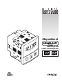
CN2110
User’s Guide
omega.com
®
®
Shop online at
www.omega.com
e-mail: [email protected]
0037-75429
Rev. 8-03

CN 2110
Omega
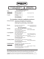
Servicing North America:
USA: One Omega Drive, P.O. Box 4047
ISO 9001 Certified Stamford CT 06907-0047
TEL: (203) 359-1660 FAX: (203) 359-7700
e-mail: [email protected]
Canada: 976 Bergar
Laval (Quebec) H7L 5A1
TEL: (514) 856-6928 FAX: (514) 856-6886
e-mail: [email protected]
For immediate technical or application assistance:
USA and Canada: Sales Service: 1-800-826-6342 / 1-800-TC-OMEGA
®
Customer Service: 1-800-622-2378 / 1-800-622-BEST
®
Engineering Service: 1-800-872-9436 / 1-800-USA-WHEN
®
TELEX: 996404 EASYLINK: 62968934 CABLE: OMEGA
Mexico: En Espan˜ol: (001) 203-359-7803 e-mail: [email protected]
FAX: (001) 203-359-7807 [email protected]
Servicing Europe:
Benelux: Postbus 8034, 1180 LA Amstelveen, The Netherlands
TEL: +31 (0)20 3472121 FAX: +31 (0)20 6434643
Toll Free in Benelux: 0800 0993344
e-mail: [email protected]
Czech Republic: Rudé armády 1868, 733 01 Karviná 8
TEL: +420 (0)69 6311899 FAX: +420 (0)69 6311114
Toll Free: 0800-1-66342 e-mail: [email protected]
France: 11, rue Jacques Cartier, 78280 Guyancourt, France
TEL: +33 (0)1 61 37 29 00 FAX: +33 (0)1 30 57 54 27
Toll Free in France: 0800-4-06342
e-mail: [email protected]
Germany/Austria: Daimlerstrasse 26, D-75392 Deckenpfronn, Germany
TEL: +49 (0)7056 9398-0 FAX: +49 (0)7056 9398-29
Toll Free in Germany: 0800 639 7678
e-mail: [email protected]
United Kingdom: One Omega Drive, River Bend Technology Centre
ISO 9002 Certified Northbank, Irlam, Manchester
M44 5BD United Kingdom
TEL: +44 (0)161 777 6611 FAX: +44 (0)161 777 6622
Toll Free in United Kingdom: 0800-488-488
e-mail: [email protected]
omega.com
®
®
OMEGAnet
®
Online Service Internet e-mail
www.omega.com [email protected]
It is the policy of OMEGA to comply with all worldwide safety and EMC/EMI regulations that
apply. OMEGA is constantly pursuing certification of its products to the European New Approach
Directives. OMEGA will add the CE mark to every appropriate device upon certification.
The information contained in this document is believed to be correct, but OMEGA Engineering, Inc. accepts
no liability for any errors it contains, and reserves the right to alter specifications without notice.
WARNING: These products are not designed for use in, and should not be used for, patient-connected applications.

CN 2110 Temperature Controller
CN 2110
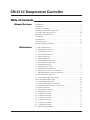
Table of Contents
1–Quick Setup ................................................................................................... 1
2–Introduction ................................................................................................... 2
3–Installation and Wiring .................................................................................. 4
4–Adjusting Setpoint and Configuration ......................................................... 12
5–Controller and Alarm Operation .................................................................. 16
6–Replacing Output Modules .......................................................................... 17
7–Calibration ................................................................................................... 19
8–Specifications .............................................................................................. 21
9–Troubleshooting ........................................................................................... 22
10–Omega Warranty and Return ..................................................................... 24
Manual Sections
Illustrations
iii
1.1 Dip Switch Settings .................................................................................. 1
1.2 Establishing the Set Point ......................................................................... 1
1.3 Adjusting the Set Point ............................................................................. 1
2.1 Front Panel Identification ......................................................................... 2
2.2 Typical Application .................................................................................. 3
2.3 Model Identification ................................................................................. 3
3.1 Default Dip Switch Settings ..................................................................... 4
3.2 Removing Mounting Collars .................................................................... 5
3.3 Mounting Dimensions .............................................................................. 6
3.4 Mounting the CN 2110 ............................................................................. 6
3.5 Wiring Terminal Identification ................................................................. 7
3.6 Thermocouple Connections with Shield .................................................. 8
3.7 Three-Wire RTD Connections with Shield............................................... 9
3.8 Two-Wire RTD Connections .................................................................... 9
3.9 Control Output Wiring–R1 and TI.......................................................... 10
3.10 Control Output Wiring–R20 ................................................................... 10
3.11 Control Output Wiring–DC .................................................................... 10
3.12 Control Output Wiring–T5 and T10 ....................................................... 11
3.13 90-260 VAC Instrument Power Connections ......................................... 11
3.14 Alarm Connections ................................................................................. 11
4.1 Establishing the Set Point ....................................................................... 12
4.2 Adjusting the Set Point ........................................................................... 12
4.3 Configuring CN 2110 ............................................................................. 13
4.4 Configuring CN 2110 ............................................................................. 13
4.5 Configuring CN 2110 ............................................................................. 13
4.6 Configuring CN 2110 ............................................................................. 13
4.7 Configuring CN 2110 ............................................................................. 13
4.8 Configuring CN 2110 ............................................................................. 13
6.1 Replacing Output Module ...................................................................... 18

CN 2110
Omega

CN 2110 Temperature Controller
CN 2110
1
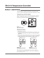
Section 1—Quick Setup
Section 1–Quick Setup
After the controller is properly wired into the system, the user only
needs to verify the sensor input and control type and adjust the set point.
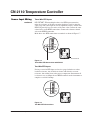
Setting the Sensor and Control Mode
Adjust the dip switches located on the bottom of the unit as shown in
Figure 1.1. The factory settings are J, TC, °F, and PI. It is simpler to
adjust the dip switch prior to mounting the CN 2110.
Figure 1.1
Dip Switch Settings
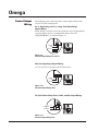
Adjusting the Set Point
1
. Apply power to the unit.
2. To adjust the set point on the CN 2110 Temperature Controller, press
and hold the Set Point button (see Figure 1.2). The Set Point light is
illuminated.
3. While still pressing the
Set P
oint button, press either the or button
to adjust the set point to the desired value (see Figure 1.3). Holding
the
or button increases the speed of the set point changes.
Figure 1.2
Establishing the Set Point
Figure 1.3
Adjusting the Set Point
Load
Alarm
°F
°C
Temp
Set
Point
Set Point
Chromalox
®
2110
Load
Alarm
°F
°C
Temp
Set
Point
Set Point
Chromalox
®
2110
The Controller is now operational with factory settings. For more
precise control, set up of the alarm, etc., see Section 4 – Adjusting Set
Point and Configuration.
J
RTD
˚C
ONOF
K
TC
˚F
PI
J
RTD
˚C
ONOF
K
TC
˚F
PI

CN 2110
Omega
2
Section 2–Introduction
Inspection and
Unpacking
Your CN 2110 controller should arrive in good condition. Upon arrival,
inspect the packaging for any visible damage.
Unpack the controller and carefully inspect for product damage that may
have occurred during shipment. If the package or contents have been
damaged in shipping, you must file a claim with the delivery service.
The delivery service will not accept a claim from the shipper.
If not immediately installing the controller, store in a cool, dry environ-
ment in its original protective packaging. Temperature extremes and
excessive moisture can damage the instrument.
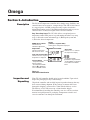
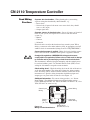
Description
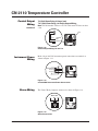
Figure 2.1
Front Panel Identification
NEMA 4X Front Panel
Construction for
hosedown applications
Output LEDs
Indicates control load
ON and alarm status
Temp and Set Point LEDs
Indicates actual or set point
temperature is displayed
Display
(4 Green, 7-Segment LEDs)
Actual process temperature displayed
Green LEDs
Indicates °F or °C selected
for temperature display
• In Operation Mode,
pushbuttons adjust Set Point.
• In Setup Mode, pushbuttons
increase/decrease MENU
values.
Set Point Button
• In Operation Mode,
adjusts Set Point
• In Configuration Mode
with the
or button,
serves as “Menu” button
Load
Alarm
°F
°C
Temp
Set
Point
Set Point
Chromalox
®
2110
The CN 2110 Temperature controller offers simple setup, flexibility and
control features in an attractive, compact design. The CN 2110 is housed
in a rugged, plastic 1/4 DIN package that only requires four inches
behind the mounting surface. Straightforward operation and easy-to-use
control features are major strengths of the CN 2110 controller.
Easy Three-Step Setup: The CN 2110 delivers exceptional process
temperature control. Your process is up and running after three easy setup
steps: 1) Select the sensor and control type, 2) Hook up the system and
3) Select the desired temperature.
Section 2—Introduction

CN 2110 Temperature Controller
CN 2110
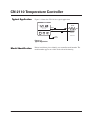
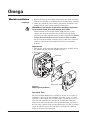
Model Identification
Before installation, please identify your controller model number. The
model number appears on a label on the side of the housing.
3
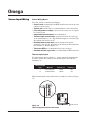
Typical Application
Figure 2.2
Typical Application
Figure 2.2 shows the CN 2110 in a typical application.
Load
Alarm
°F
°C
Temp
Set
Point
Set Point
Chromalox
®
2110
Alarm
Output
Process
Heater
Output
Input
Sensor
Section 2–Introduction

CN 2110
Omega
4
Section 3–Installation and Wiring
Section 3—Installation and Wiring
Sensor and Control
Type Selection
Switches
Set the CN 2110 controller’s configuration via mechanical dip switches,
located on the bottom of the unit. Factory settings are J, TC, °F, and PI
Control. Switches are easier to set before mounting.
To change the switch settings, first disconnect all wiring and power
from the unit. Adjust switch settings as follows:
Setting Factory
Switch Function Options Setting
A Thermocouple J or K J
B Input Type TC or RTD TC
C Temperature Units °F or °C °F
D Control Type ON-OFF or PI PI
If input type is thermocouple, switch A selects either thermocouple type
J or K.
Switch B selects input type thermocouple or RTD (resistance tempera-
ture detector). Note: If RTD is selected, switch A is ignored.
Switch C selects temperature units
°F or °C.
Switch D selects either PI (Proportional-Integral) or ON-OFF control.
Figure 3.1
Default Dip Switch Settings
J
RTD
˚C
ONOF
K
TC
˚F
PI
J
RTD
˚C
ONOF
K
TC
˚F
PI

CN 2110 Temperature Controller
CN 2110
5
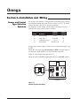
Mounting
Two mounting collars securely hold the CN 2110 controller in the
mounting hole. Remove these mounting collars before installation.
Removing Mounting Collars
1. To remove the rear collar, press the sides of the collar. This releases
holding tabs on the top and bottom of the collar.
2. Slide the collar off the back of the unit.
3. Slide the front collar off the back of the unit
Figure 3.2
Removing Mounting Collars
Holding
Tabs
Front Collar
Rear Collar
Press In
Press In
Section 3–Installation and Wiring
continued

CN 2110
Omega
6
Section 3–Installation and Wiring
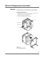
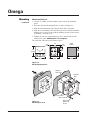
Figure 3.3
Mounting Dimensions
Figure 3.4
Mounting the 2110
Mount the CN 2110
1. Cut out a 1/4 DIN, 3.6-inch (92mm) square hole in the mounting
panel.
2. Insert the unit into the mounting hole as shown in Figure 3.4.
3. Slide the front mounting collar onto the back of the controller.
4. Slide the rear mounting collar onto the back of the controller until the
holding tabs securely engage with the holding tab slots in the control-
ler housing (see Figure 3.4).
5. Tighten the four rear collar mounting screws until the unit is held
firmly in the panel.
CAUTION: Do not overtighten.
The controller will now be held firmly in place.
Load
Alarm
°F
°C
Tem p
Set
Point
Set Point
Chromalox
®
2110
4.0
(101.6)
4.0
(101.6)
4.0
(102)
3.6
(92)
3.6
(92)
3.55
(90)
3.6
(92)
0.4
(10)
0.5
(12.7)
Panel
Cutout
Front Collar
Rear Collar
Rear Collar
Mounting
Screw
Holding
Tabs
Holding
Tabs Slots
Mounting
continued

CN 2110 Temperature Controller
CN 2110
7
Good Wiring
Practices
Separate wire into bundles—When planning the system wiring,
separate wiring into functionally similar bundles, e.g.
• Power leads
• Sensor leads (if power leads must cross sensor leads, they should
cross at a 90° angle)
• Output signal lines
Separate sources of electrical noise—Locate all sources of electrical
noise in your system, and separate these sources from the control
system, e.g.
• Motors
• Contacts
• Solenoids
Electrical noise can affect the function of any control system. When
driving a contactor coil or other inductive load, an appropriate rated AC
snubber circuit is recommended (Omega Part No. CNQUENCHARC).
Connect before power is applied—Make all electrical wiring connec-
tions to the back of the controller before power is applied to the unit.
Comply with regulations—WARNING: All wiring practices must
comply with local regulations. Failure to do so could result in damage
to controller and/or personal injury or death from electrical shock.
This instrument is intended for panel mounting and the terminals must
be enclosed within a panel. Use National Electric Code (NEC) Class 1
wiring for all terminals except the sensor terminals.
Check wiring decal—Check the wiring decal on the side of the unit to
verify the model number. The wiring decal shows the wiring termina-
tions. All wiring will be connected to the terminals on the back of the
instrument case. Specific wiring instructions for different input and
output types are given in this section. See also Figure 3.5.
Additional information—For sensor wiring practices, see “Sensor
Input Wiring”. For additional information on good wiring practice,
request IEEE Standard No. 518-1982 from IEEE, 345 East 47
th
St., New
York, NY 10017 or www.ieee.org.
Figure 3.5
Wiring Terminal Identification
!
NC
NO
COM
Sensor Input
Wiring
Output
Wiring
(T5, T10)
Output Wiring
(R1, R20, DC, or T1)
Instrument
Power Wiring
Alarm Wiring
Section 3–Installation and Wiring

CN 2110
Omega
8
Section 3–Installation and Wiring
Sensor Input Wiring
Sensor Wiring Notes
For safety and best controller performance,
•
Sensor leads (thermocouple and RTD) should not be run in the same
conduit as power wiring.
•
Twisted pair, shielded wire is recommended for sensor connections.
•
False temperature readings can occur if the sensor wire is exposed
to electrical noise.
•
Ungrounded thermocouples are recommended.
•
Thermocouple extension wire, if required, must be the same type
as the thermocouple (i.e. if a Type K thermocouple is used, then Type
K extension wire must be used.)
• Shielded thermocouple wire, if used, must have the shield
grounded at one end only, preferably at the shield ground terminal on
the controller as shown in Figure 3.6.
•
Three-wire RTDs are recommended for greatest accuracy.
•
Standard shielded copper wire
is recommended for RTD extensions.
Thermocouple Inputs
It is important to observe polarity (+,-) when connecting thermocouple
leadwires. ANSI color coding for the thermocouples used with this
instrument are
Thermocouple
Type Material Polarity (+) Polarity (-)
J iron/constantan white red
K chromel/alumel yellow red
Make thermocouple wiring connections to terminals as shown in Figure
3.6.
Figure 3.6
Thermocouple Connections with Shield
TC -
NC
NO
COM
TC +
Shield Ground

CN 2110 Temperature Controller
CN 2110
Three-Wire RTD Inputs
IMPORTANT: When making the three-wire RTD input connection,
make the resistance of all three extension leadwires equal by using the
same gauge and same length of wire for optimum accuracy. A three-wire
RTD will generally have two wires of the same color. Connect the same
colored wires to the RTDL connections. Connect the alternate colored
wire to the RTDH connection.
Make three-wire RTD connections to terminals as shown in Figure 3.7.
Two-Wire RTD Inputs
If using a two-wire RTD input, use heavier gauge leadwires to reduce
leadwire resistance. Any leadwire resistance adds directly to sensor
resistance, thus adding error to the process temperature measurement. It
is also necessary to jumper the two RTDL terminals on the instrument to
complete a two-wire hookup.
Figure 3.7
Three-Wire RTD Connections with Shield
Figure 3.8
Two-Wire RTD Connections
NC
NO
COM
RTDL
RTDH
RTDL
9
Section 3–Installation and Wiring
Sensor Input Wiring
continued
RTDL
RTDH
RTDL
NC
NO
COM
Shield Ground

CN 2110
Omega
Control Output
Wiring
Figure 3.9
Control Output Wiring–R1 and T1
Figure 3.10
Control Output Wiring–R20
Figure 3.11
Control Output Wiring–DC
The following figures show the proper control output wiring for the
various CN 2110 configurations.
10
R1 (1 Amp Relay) and T1 (1 Amp, Solid State Relay)
Output Wiring
When driving a contactor coil or other inductive load, an appropriately
rated AC snubber circuit is recommended (Omega Part. No.
CNQUENCHARC), as shown in Figure 3.9.
R20 (20 Amp Relay) Output Wiring
1/4” fast-on tabs are provided with the R20 output.
DC (Solid State Relay Drive, 24Vdc, 40mA) Output Wiring
Section 3–Installation and Wiring
NC
NO
COM
Fuse
Load
Snubber
120/240
VAC
Neutral
Fuse
Load
120/240
VAC
Neutral
NC
NO
COM
NCNO
COM
NO
COM
NC
NO
COM
Fuse
Load
120/240VAC
AC Neutral
+
+
-
-
SSR
4115

CN 2110 Temperature Controller
CN 2110
Figure 3.12
Control Output Wiring–T5 and T10
T5 (Solid State Relay, 5 Amps) and
T10 (Solid State Relay, 10 Amps) Output Wiring
Note: CN 2110 model T10 has a fan. CN 2110 model T5 does not have
a fan.
11
NC
NO
COM
Fuse
Load
120/240
VAC
Neutral
Instrument Power
Wiring
Make 120 or 240 VAC instrument power connections to terminals as
shown in Figure 3.13.
Alarm Wiring
The Form C Relay Output is connected as shown in Figure 3.14.
Figure 3.13
90-260 VAC Instrument Power Connections
Figure 3.14
Alarm Connections
CNO
Alarm Out
NC
NC
NO
COM
NC
NO
COM
120/240VAC
Neutral
Ground
NC
NO
COM
Section 3–Installation and Wiring
Control Output
Wiring
continued
Fan

CN 2110
Omega
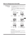
To access the user configuration menus,
1. Press and hold the
and buttons. After three seconds the display
will begin to toggle between the current security code and LocH
(LOCK). The Temp and Set Point LEDs will turn on. See Figure 4.3.
2. Press the
or button to adjust the value to the appropriate security
number (see Security Codes and Levels). Only the value is displayed
during adjustment. See Figure 4.4.
3. Press and hold the Set Point ( ) button and press the or
buttons to scroll the configuration menus. The display will show the
name of the menu and then begin to toggle between the name and the
current value. See Figures 4.5 and 4.6.
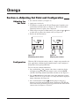
Adjusting the
Set Point
1. Set selection switches (see Figure 3.1).
2. Apply power to the unit.
3. To adjust the set point on the CN 2110 Temperature Controller, press
and hold the Set Point button (see Figure 4.1). The Set Point light is
illuminated and the set point value is displayed.
4. While still pressing the
Set P
oint button, press either the or button
to adjust the set point to the desired value (see Figure 4.2).
5. Release the
Set P
oint button.
While the CN 2110 default settings make it a simple setup controller for
most applications, additional programmable menus can be configured
through three front-panel pushbuttons.
Configuration
Figure 4.1
Establishing the Set Point
Load
Alarm
°F
°C
Temp
Set
Point
Set Point
Chromalox
®
2110
Load
Alarm
°F
°C
Temp
Set
Point
Set Point
Chromalox
®
2110
Figure 4.2
Adjusting the Set Point
12
Section 4–Adjusting Set Point and Configuration
Section 4—Adjusting Set Point and Configuration

CN 2110 Temperature Controller
CN 2110
13
Section 4–Adjusting Set Point and Configuration
Load
Alarm
¡F
¡C
Temp
Set
Point
Set Point
Chromalox
¤
2110
Load
Alarm
¡F
¡C
Temp
Set
Point
Set Point
Chromalox
¤
2110
Load
Alarm
°F
°C
Tem p
Set
Point
Set Point
Chromalox
®
2110
Figure 4.3
Figure 4.5
Figure 4.6
Figure 4.4
Figure 4.7
4. Press the or buttons to adjust the value (only the value is dis-
played during adjustment). See Figure 4.7. The new value is set when
the
or button is released.
5. Press and hold the Set Point (
) button and press the button to
advance to the next menu. See Figure 4.8. (Holding the Set Point
( ) button and pressing the button moves through menus in the
opposite direction.)
Repeat steps 4 and 5 through the configuration menus.
Exit Configuration
To exit configuration mode, press and hold both the
and buttons for
three seconds to return to the operation mode.
Note: If no buttons are pressed for three minutes while in user configu-
ration mode, then the controller will exit user configuration and return to
the operation mode.
Load
Alarm
¡F
¡C
Tem p
Set
Point
Set Point
Chromalox
¤
2110
Figure 4.8
Load
Alarm
¡F
¡C
Tem p
Set
Point
Set Point
Chromalox
¤
2110
Load
Alarm
¡F
¡C
Tem p
Set
Point
Set Point
Chromalox
¤
2110
Configuration
continued
Adjust lock
to 458
Move to
next menu
Continue
until SP is
displayed
Adjust the
set point
value
Continue
through the
configuration
menus

CN 2110
Omega
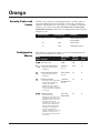
Security Codes and
Levels
To limit access to the user configuration interface, security codes are
assigned to different menu levels. Make security codes available to
operators, maintenance crew, supervisors, etc. according to what func-
tion level you want for each group. Security Level C is not recom-
mended for most users. Gain access to configuration menus using the
following codes.
Security Level Security Code Function
A All Values Allows adjustment of
the Set Point
B 458 Basic menus
C 736 Calibration menus
Configuration
Menus
The following configuration menus can be accessed through the user
interface (see Configuration, page 12).
Menu Adjustable Factory Security
Code Function Range Default Level
Security Lock
Read Only
°F or °C
N/A
Process Variable Display
Displays the actual process
temperature.
Process Set Point Adjust
Adjusts the target process
temperature.
Proportional Band
Temperature range above/below
set point where proportional
control is active. Most
applications require a band
between 10 to 200°F. This menu
is active only when the dip switch
is set to “PI”
Automatic Reset
Control feature that
automatically corrects for small
temperature offsets that occur in
proportional control. The higher
the setting, the faster the
correction occurs. A high setting
could cause overshoot during
start-up. A low setting will not
allow process temperature to
reach to set point quickly
enough. A setting of “0” turns off
automatic reset. This menu is
active only when the dip switch
is set to “PI”.
Sensor Range
°F or °C
0°F
1 to Sensor
Span Maximum
°F or °C
25
0.0 to 100.0
Repeats/Min.
0.1
0-999 458
A
A
B
B
A
14
Section 4–Adjusting Set Point and Configuration

CN 2110 Temperature Controller
CN 2110
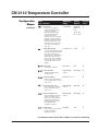
On/Off Dead Band
The range above/below set point
in which no control action takes
place. Determines at what
temperature the output switches
ON and OFF. For a 5°F dead
band, 2.5°F is above and below
the set point. This menu is active
when the dip switch is set to
“ONOF”.
Alarm Type
Select high or low alarm.
Alarm Set Point
Temperature level that will
actuate the alarm.
Alarm Dead Band
Difference of temperature from
alarm set point before an active
alarm resets.
Set Point Upper Limit
Upper limit to which set point
may be set without security
code access. This prevents an
operator from setting the set
point temperature to a level
which would damage
equipment or process.
Set Point Lower Limit
Lower limit to which set point
may be set without security
code access.
Output Limit
Limits the percentage of output
that can be applied in
proportional control.
1 to 100 °F or °C5 Foc
Off, Hi or Lo OFF
Sensor Range
°F or °C
Span High
0 to 100 °F or °C5
Sensor Range
°F or °C
Span High
Sensor Range
°F or °C
Span Low
0 to 100% 100
B
B
B
B
B
B
B
15
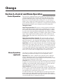
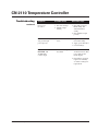
Cycle Time
The time for the output to
complete ON to OFF to ON
cycle. Used only with
proportional control. A fast
cycle time provides better
control, but can cause
premature wear to contactor or
other power switching devices.
Magnetic contactors should not
be switched at less than a 30
second cycle time. This menu is
active when the dip switch is
set to “PI”.
.1 to 60.0 Sec. Output R1,
R20 = 30
sec.
T1, T5, T10
DC = 1 sec.
B
Section 4–Adjusting Set Point and Configuration
Configuration
Menus
continued
Menu Adjustable Factory Security
Code Function Range Default Level
For calibration menus (CoFF, dFLt, & CALS), see Section 7–Calibration

CN 2110
Omega
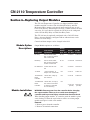
Control Operation
The CN 2110 is shipped from the factory with PI (proportional/integral)
control. Proportional control actually determines the percent of heat
needed to control the process. The factory setting for the Proportional
Band is 25°F and the Automatic Reset (Integral) is set at 0.1 repeats/
minute. These settings will control many processes without any changes
to the controller.
If the process is unstable or too sluggish, the Proportional
Band and Automatic Reset can be changed in the menu configuration.
Tuning PI Control
Adjust Proportional Band
The objective of the proportional band adjust-
ment is to find the proportional band setting at which the process tempera-
ture stabilizes and does not oscillate. If the temperature display is oscillat-
ing, increase the Proportional Band (doubling the value) until the tempera-
ture display has stopped oscillating. To establish a quick response to control
upsets, adjust for the smallest band that provides stable control (does not
oscillate). Note: The temperature at this point may not be at set point, but
will be stable.
Adjust Automatic Reset (Integral) The Automatic Reset (Integral)
automatically removes the offset between process temperature and set
point. If the process is too sluggish in approaching set point, double the
automatic reset. Too much automatic reset will make a process unstable.
Cycle Time
Cycle time setting determines how often to switch the output
to the heater. For example, if the cycle time is 1 second and the CN 2110
needs a 75% output, the output will be on for 3/4 of a second and off 1/4
of a second. Units with relay control outputs (R1 or R20) are shipped with
a 30-second cycle time. Units with solid state relays or solid state relay
drives (T1, T5, T10, or DC) are shipped with a 1-second cycle time.
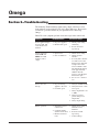
Section 5—Control and Alarm Operation
Alarm Operation
(optional)
16
Section 5–Control and Alarm Operation
An alarm relay output is optional on the CN 2110. An alarm can help
protect the process when a too high or too low temperature occurs.
High Alarm:
This alarm is a high absolute alarm that actuates when the
process temperature is equal to or greater than the alarm set point. For
example, if the high alarm set point is 500°F, the alarm will always actuate
when the process temperature reaches 500°F.
Low Alarm:
The low absolute alarm actuates when the process temperature
is equal to or less than the alarm set point. The low alarm features a power-
up inhibit to prevent undesirable alarms during process start up. After the
unit reaches control set point, the low alarm will respond.
Alarm Dead Band:
The alarm relay de-energizes (resets) when the tem-
perature crosses out of the alarm dead band. For example, if the high alarm
is set to 500°F and the alarm dead band is 5°F, the alarm condition will not
reset until the process temperature reaches 495°F.
To enable the alarm relay, select either high or low alarm type and set the
alarm set point. An alarm condition is indicated when the Alarm light to
the left of the display illuminates. Alarm type, set point, and dead band are
selectable through the user configuration interface.
Page is loading ...
Page is loading ...
Page is loading ...
Page is loading ...
Page is loading ...
Page is loading ...
Page is loading ...
Page is loading ...
Page is loading ...
Page is loading ...
Page is loading ...
Page is loading ...
-
 1
1
-
 2
2
-
 3
3
-
 4
4
-
 5
5
-
 6
6
-
 7
7
-
 8
8
-
 9
9
-
 10
10
-
 11
11
-
 12
12
-
 13
13
-
 14
14
-
 15
15
-
 16
16
-
 17
17
-
 18
18
-
 19
19
-
 20
20
-
 21
21
-
 22
22
-
 23
23
-
 24
24
-
 25
25
-
 26
26
-
 27
27
-
 28
28
-
 29
29
-
 30
30
-
 31
31
-
 32
32


Omega Omega CN2110 User manual
- Type
- User manual
- This manual is also suitable for
Ask a question and I''ll find the answer in the document
Finding information in a document is now easier with AI
Related papers
-
Omega CN2120 Owner's manual
-
-
-
-
-
-
-
-
-
Other documents
-
Chromalox 2110 User manual
-
-
-
-
-
-
-
Chromalox 3101 Installation guide
-
-